[Trade Journal]
Publication: Power
New York, NY, United States
vol. 19, no. 4, p. 8-9, col. 1-4
Insulators.
The average reader probably never stopped to think of the immense importance that attaches to an apparently insignificant portion of every electric power plant, namely, the insulators. But for the existence and use of these humble contributors to the efficiency of the system, the cost of line wire in low potential plant would be enormously high on account of the great thickness and perfection of the insulation on the wit e itself, while the cost of insulation on high tension power transmission wires would be simply prohibitive. As it is with the best forms of pole insulators and high grade covering on the wire it is a difficult matter to keep a high-tension circuit free from leakage, or "grounds."
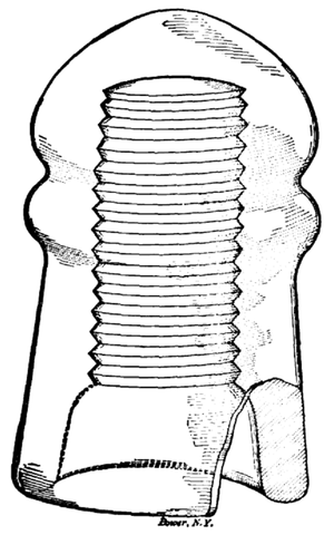
In the early days of electrical science when the telegraph circuits were the heaviest, and in fact, about the only kind in use, plain wooden insulators were used. For even this light current, wood was immediately found to be inefficient on account of its ready absorption of moisture, which is a sufficiently good conductor to cause very detrimental leakage.' Consequently insulators of glass were brought into service; rubber was also' used to a limited extent. but its ex- pensiveness soon restricted it to: special cases of interior work. The "Western Union" type of insulator, shown by Fig. 1, is probably the oldest, and is universally used for, lines of moderate length and light service.
 |
| Fig. 1. |
 |
| Fig. 2. |
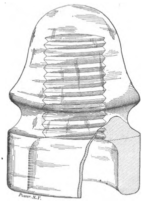
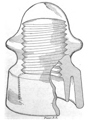
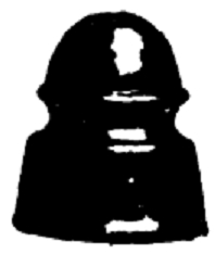
When electric power circuits came into service the same insulators were at first used that had been used in telegraph work, but it was found that moisture would cover the surface of the glass and form a leak from the wire to the wooden pin on which the insulator was mounted, and thence to the ground. This resulted in the production of the "deep-groove" insulator, shown by Fig. 2, originated by Win. Brookfield, and extensively used for ordinary pressures. For railway circuits, where one side of the circuit is grounded, the tendency to leakage is so much greater than in other power circuits that it was found advisable to cut another groove in the under edge of the glass, to retard still further the creeping of moisture from the outside to the inside of the bell. This gave the "deep-groove double petticoat" insulator, as shown by Fig. 3, which is now the standard for railway feeder lines.
 |
| Fig. 3. |
 |
| Fig. 4. |
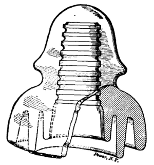
For higher potentials (3,000 to 45,000 volts), a type of insulator originated by F. M. Locke, of Victor, N. Y., and known as the "triple petticoat," is now extensively used; Fig 4 shows this type. Over 75,000 of these insulators are in use.
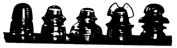 |
| Fig. 5. |
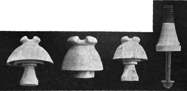
Fig. 5 shows a group of glass insulators which includes the representative types manufactured by William Brookfield, of New York. On the extreme left is the ordinary insulator for light service; next comes the double petticoat railway feeder insulator; in the center is a triple petticoat Locke insulator for high potentials; next comes a cable insulator and on the extreme right is a "transposition" insulator. The first three of the group have been described.
The transposition insulator is used when it is desired to change the position of a wire from one location to another on the cross-arm. This is necessary where telephone wires run on the same poles with heavy power circuits; the induction front the heavy current wires interferes with the telephone circuit if the wires are run straight, so they are changed every few poles, one side of the circuit exchanging positions with the other side. This neutralizes the induction, and it is where this change-over takes place that transposition insulators are used.
The cable insulator is intended to support heavy overhead cables, the usual custom being to lay the cable in the slot across the top of the insulator and secure it in place by means of a tie wire passing beneath the wings or lugs on each side. These insulators are made in huge sizes, some of them standing 10 inches high. The mechanical strain on them is very great, the cable being usually lead-covered and consequently extremely heavy. The electrical strain is not so great, as the cable is thoroughly insulated by its covering; hence the interior is like that of an ordinary Western Union insulator, or else like a deep-groove insulator.
The manufacture of glass insulators as practised at the Brookfield works, Greenpoint, L. I., is interesting. A combination of silica, carbonate of soda and lime is put in a furnace and heated to about 2,500 degrees, when it becomes glass. The workmen stand around one end of the furnace, which is curved, and through openings in it they take out little "wads" of glass on the ends of rods, the glass not being fluid enough to pour like cast iron. The glass is dexterously carried from the furnace to the molds on the ends of the rods, and cut off with big shears when a mold is full. Then pressure is applied to the glass in the mold to force it into all the crevices, and as soon as it "sets" (at the end of 10 or 15 seconds) the insulator, still red hot, is taken to an annealing oven. This oven is maintained at a beat of about 800 degrees while it is being filled, and as soon as it is full the doors are closed, the heat withdrawn, and the oven is allowed to cool. To cool the insulators down to "handling" temperature requires about three days.
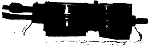 |
| Fig. 6. |
The molds are usually made of cast iron, highly polished inside so as to give the insulator a glossy surface, and they require frequent cleaning to keep the interior smooth. The hot glass oxydizes the surface of the mold and every time it is cleaned a very thin scale is taken off. Consequently the mold becomes imperfect after repeated cleanings and is discarded. Fig. 6 shows a mold open. The working capacity is about 35 telegraph insulators an hour for each mold. The larger the insulator, the fewer can be turned out, of course.
 |
| Fig. 7. |
 |
| Fig. 8. |
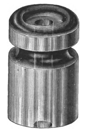
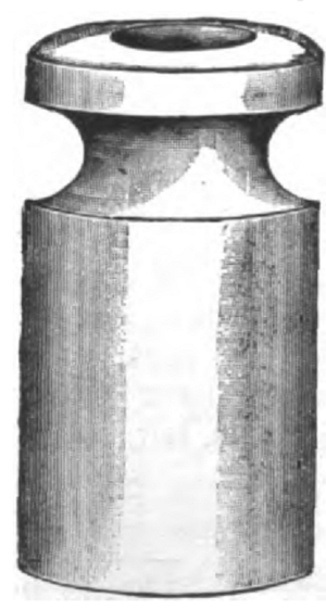
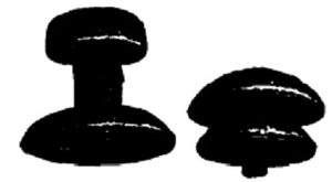
For interior wiring different forms of insulators are used. Not having the elements to contend with, the precautions of mounting an insulator on the tip of a pin and forming grooves in its under surface to retard the creeping of moisture are unnecessary. Hence plain knobs like Fig. 7 are used in many cases for supporting "open" wiring. These are simply screwed to the woodwork of the building. The great majority of knob insulators are made of china (so-called porcelain) or earthenware, consisting of vitreous clay, hard-baked and then glazed, like Fig. 8, although a good many glass knobs like Fig. 7 are also used.
 |
| Fig. 9. |
 |
| Fig. 10. |
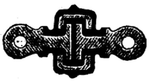
Figs. 9 and 10 show special forms of china insulators designed to save time in fastening the wire to the knobs. These are made by Pass & Seymour, of Syracuse. N. Y., and are extensively used. The cuts are so plain that explanation is hardly necessary. The knobs do away with the use of tie-wires, which are required where the ordinary knobs are used. Fig. 11 shows a form of interior, insulator which has met with universal favor for carrying surface wiring. It is a split cleat adapted to clamp both of the wires of a circuit at once, as shown in the illustration.
 |
| Fig. 11. |
 |
| Fig. 12. |
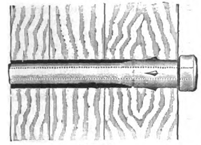
For carrying a wire through woodwork, such as flooring, window frames, door frames, etc., Pass & Seymour make a form of china insulating tube like that shown by Fig. 12. This precaution is necessary to avoid electrical leakage and damage to the wire insulation by moisture, and it is also advisable to protect the insulation from mechanical injury.
 |
| Figs. 15, 13, 14 and 17. |
Porcelain, or rather glazed earthenware (china), has been found such an excellent insulating material that F. M. Locke has designed a full line of china insulators for out-door work, and they have been widely used on high-tension circuits. Figs. 13 to 15 show the types most used. Fig. 13 is a double-petticoat insulator for potentials up to 5,000 volts, made 3 ½ inches in diameter. It will be noticed that the wire groove is across the top of the bell instead of around the side as in the case of the glass insulators. This is so in order to put the wire just as far as possible, electrically, away from the pin on which the insulator is supported; another reason is to transmit the weight of the wire directly downward to the end of the pin, avoiding all twisting or tilting strains. With the wire in this position any leakage must be downward the full length of the bell, up the interior to the inner petticoat, down that petticoat and up its interior wall to the pin.
When very high potentials are used, there is danger of "flashing across" from the lower edge of the bell to the pin, if both are heavily coated with moisture. To avoid this Mr. Locke devised the "triple petticoat" type of insulator mentioned above. Fig. 14 shows a china insulator of this type; the chief difference between this and the central insulator of the glass group is the location of the wire groove. The one shown by Fig. 14 is intended for potentials of 20,000 volts, and is 5 ½ inches in diameter. Fig. 15 shows a 45,000 volt insulator which is 7 inches in diameter, the increased "spread" at the bottom being for the purpose of preventing the current from leaping across as mentioned above. Fig. 14 insulator is most used, as it is designed for a range of potential which includes the transmission voltages of all the big plants; 50,000 of these insulators are in use.
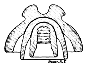
The china insulators are not molded in one piece like the glass ones. The double-petticoat is molded in two pieces and the triple-petticoat in three. The pieces are made of wedge clay," which is moistened to plasticity, thoroughly mixed and compressed in molds. After they are thoroughly vitrified the pieces are glazed and then "nested, as shown by the sectional view, Fig. 16, and fused together.
 |
| Fig. 16. |
Mr. Locke also makes a high-resistance insulator pin, shown by Fig. 17, which consists of a steel shank carrying a china sheath surmounted by a wooden screw tip. The principal object of this construction is to increase the resistance to leakage, but a strong feature of the pin is the smallness of the hole required in the, cross-arm. This, of course, decreases the liability to splitting out, and entirely obviates the rotting off which is such a nuisance with wooden pins. The steel shank is galvanized, to prevent the formation of rust; over 200,000 of these pins are in service.
One branch of power transmission possesses features peculiar to itself which demand special forms of insulators, and it has attained such colossal proportions as to justify the production of such insulators in almost fabulous quantities. This branch is electric railway work. Besides the double-petticoat glass insulator (Fig. 3) for carrying line wires, a number of special types are used for special purposes. In nearly all of these, glass and china have been found too brittle to withstand the shocks and blows incidental to railway operation, and molded mica has been adopted with universal satisfaction.
 |
| Fig. 19. |
 |
| Fig. 20. |
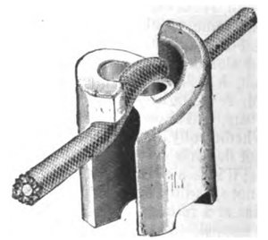
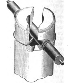
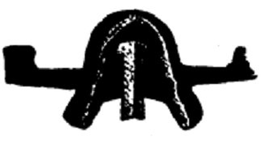
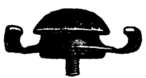
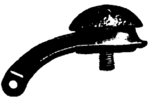
Figs. 18 to 29 illustrate the leading forms of railway insulators made by the H. W. Johns Manufacturing Company, of New York. Fig. 18 is a trolley wire hanger for straight lines, and Fig. 19 shows a part of the bell cut away, exposing the molded mica and screw stud. This form is preferred by some engineers because the mica insulation is protected from blows of the trolley wheel. The form shown by Fig. 20 is, however, widely used. This consists of a malleable iron ring with ears, carrying a screw stud, insulated as shown by Fig. 21; this type is designated the "cap and cone" hanger, because of the shape of the insulation. The cap is separable from the cone for insertion and removal in and from the malleable ring.
 |
| Fig. 21. |
 |
| Fig. 22. |
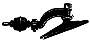
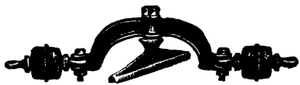
Where the line curves the trolley wire has to be held sidewise, of course, to preserve its alignment with the track. For this service the straight line hangers are not suited, and "pull-overs" are used. Fig. 22 shows a "pull-over" with cap and cone insulation. A trolley wire clip or ear is screwed to the steel and a heavy galvanized iron wire extends from the eye in the arm to a pole or other stable object on the outside on the curve. A form of pull-over which is probably better suited for very heavy work is the "Giant," shown by Fig. 23. Here the trolley wire clip is not insulated from the curved arm at all, but the latter is insulated from the stay-wire by the ball-shaped device on the left, known as a "strain insulator."
 |
| Fig. 23. |
 |
| Fig. 24. |
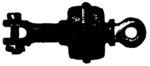
Fig. 24 sows this on a larger scale, and Fig. 25 shows the interior construction. The eye-bolts terminate inside the mica in circular plates. These are inserted in a cylinder with flanged ends, and the whole surrounded by mica. The mechanical strain is transmitted from eye-bolt to eye-bolt through the cylinder flanges and the intervening mica, the latter thus being under compression and not a disintegrating strain. No strain comes upon the surrounding envelope of molded mica. The mica between the plates and that between the plates and flanges is in sheet form, the interstices being filled by molded mica, forced in by the external pressure. These "Giant" strain insulators have come into universal use on trolley lines. One company alone has purchased 22,000 of them within the past year.
 |
| Fig. 25. |
 |
| Fig. 26. |
This form of insulator is also used to hold up the bight of a heavy feeder running from the pole out to the trolley wire; the insulator is tied to the pole by an iron wire in one eye, and the end of the feed wire is threaded through the other eye, tied, and then led-up loosely to the feeder line on the pole. Thus the weight of the pole end of the feeder running out to the trolley is borne by the Giant strain insulator instead of by the glass insulator and its pin on the cross-arm.
Where a line is double-tracked and two trolley wires must be pulled over at the curves, a double pull-over, such as that shown by Fig. 26, is used on the outside wire, and a single pull-over on the inside wire. A strain, or pulling wire, extends from the single pull-over to one end of the double one, and another strain wire goes from the other end of the double pull-over to the anchorage on the sidewalk.
 |
| Fig. 27. |
 |
| Fig. 28. |
 |
| Fig. 29. |
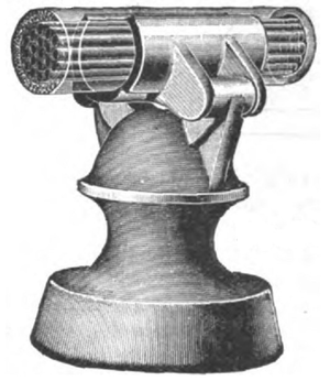
Although glass insulators are used in thousands for supporting railway feed wires, the extreme length of the feeders in large plants sometimes occasions excessive leakage, and in this case molded mica is generally used. Fig. 27 shows such an insulator, similar in shape to the familiar glass article so widely used. It also happens in large plants that the feeders are too heavy to support by tying them in a groove in the side of an insulator. To meet this emergency the Johns Company has devised what is known as a toggle-clamp insulator; Fig. 28 shows this. The insulator is of molded mica, sheathed with a malleable iron shell for mechanical protection. The metal shell carries two pivoted jaws on top, and the weight of the wire, when it is placed in these jaws, causes them to clamp it with a powerful toggle-lever action.
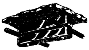
On lines of any length it is customary to divide the trolley wire up into sections, so that an accident in one section will not shut down the whole road. For mechanically connecting the contiguous ends of the trolley wire of neighboring sections, without metallic (electric) connection, the "Philadelphia break," shown by Fig. 29, is widely used. This consists of a fiber slab twelve inches long, carrying a metal clip at each end. The ends of the trolley wires are secured to these metal clips, and the trolley wheel is thus furnished with a continuous track from one section to the next.
The fiber piece is made of a special sort of material, not the ordinary market fiber. It is of such a character that it does not swell and warp when exposed to the weather, as does the product usually found in open market, but retains its alignment with the trolley wire. The "Philadelphia break" obtained its name from the fact that it was first adopted and is used throughout by the huge trolley systems of Philadelphia. While the standard length of fiber is twelve inches, these "breaks" or section insulators are made in any length up to 24 inches; beyond this it is undesirable to go because of mechanical reasons.
There are many variations of the several forms of insulators here described, which space limitations forbid even enumerating. The types shown, however, are representative, and serve well to illustrate American practice in the insulation of all classes of circuits for the electrical transmission of power.
