[Trade Journal]
Publication: Electrical Record
New York, NY, United States
vol. 11, no. 3, p. 128-136, col. 1-2
HIGH-TENSION LINE MATERIALS
[FIRST ARTICLE]
BY HARRY BARNES GEAR
MATERIALS and fittings used in connection with hightension transmission and distribution lines are of a widely varying and often highly specialized character. To those inexperienced in such construction it is a source of great perplexity to determine what type of equipment should be selected for the particular case in hand to secure the desired results. Indeed, this perplexity is not wholly confined to the inexperienced. It will be the purpose of these articles to describe and illustrate the principal materials and some of the various types of fittings which are used in connection with transmission and distribution work at voltages above 600, and to indicate the limits within which these are commonly used.
The problems of line construction are peculiar in that they require for their solution an accurate knowledge of the conditions under which lines are to be operated. The manufacturer of electrical apparatus may employ designers to work out prime movers, generators, motors, incandescent lamps, heating devices, and various other forms of electrical equipment in their factory laboratories and drafting rooms. These devices may be experimented with. re-designed, and brought to a high state of perfection before they are sent out of the factory in commercial shape and the manufacturers engineers become leaders in these lines of development.
But with transmission devices the problem is far more difficult. The drafting room designs maybe worked up and gotten into commercial shape, but the manufacturer cannot provide adequate facilities for submitting his devices to a practical test except through the co-operation of operating companies who purchase his apparatus and try it out in actual service. After a year or more experience, the device may prove to be lacking in so1ne important particular, and the manufacturer must depend upon the operating men to suggest to him the lines along which improvements can be made. The cycle is then repeated, and. after a series of such experiments extending through a number of years, the device, if inherently good, becomes standard, or, if not, may be discarded or completely rehabilitated.
In the meantime, the operating engineer may have been driven to his own devices to keep his system going. Possibly he has worked out some form of apparatus which is better adapted to the work than that which has been devised by the manufacturers engineers. The operating engineer, being in daily touch with conditions in the field is capable of forming a more accurate idea of his requirements than is possible for the manufacturer.
It is, therefore, very important that manufacturers cultivate friendly relations with operating engineers and thus keep in close touch with conditions in the field. This is necessary both for the purpose of making needed improvements in existing devices and for the discovery of new fields for fittings which changing conditions may require from time to time.
POLES
In overhead distribution the selection of poles is one of the most important factors affecting the continuity of the service and permanence of investment. The pole line must not only be of ample strength to withstand the strains to which it is subjected under normal conditions, but must be capable of withstanding extra stresses placed upon it from time to time during storms when the wind pressure is very great or when the wires are laden with a coating of sleet. At such times the failure of a single pole at a critical point in the line, may sometimes throw additional stresses on adjacent poles sufficient to break them off for a considerable distance each side of the break, thus putting a line out of service at a time when it is very difficult to make repairs, and in a way which it may require days to repair.
The materials used for poles have, therefore, been adjusted in recent years in accordance with the service for which the pole is intended and the exposure to which it is likely to be subjected. Poles of wood, concrete and steel are used in various places; and on heavy transmission lines the steel pole has been replaced by the steel tower of even greater strength than it is possible to obtain in a pole.
WOODEN POLES
Wooden poles are specially adapted to the construction of distribution lines at the lower voltages where it is necessary to make connections on live circuits every day and where the insulation afforded by the wood is a practical necessity. The use of poles having metal in their construction is very dangerous where work must be done on circuits while they are alive, and the wooden pole will continue to be used for an indefinite period for all distribution where high-tension circuits are carried on the poles. The comparatively light weight, ease of handling and climbing, and low cost are of very material advantage to those who are constructing and operating distributing systems.
| |||
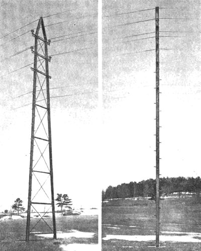
| Fig. 1.Wooden Pole Line, 100-150 Ft. Span |
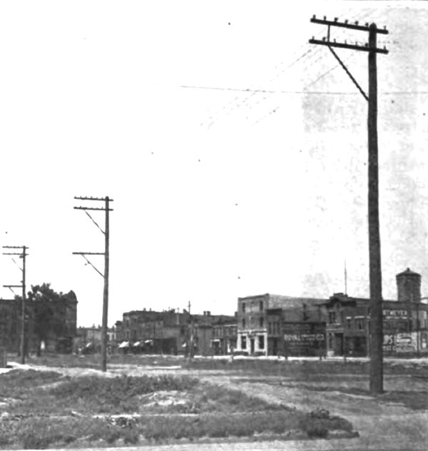
Wooden poles are desirable for the same reasons in transmission work where there are distribution lines carried on the same poles and where lines are carried along public highways or over rights-of-way which are not owned by the transmission company. In such lines the spans must usually be between 100 and 150 feet, as shown in Fig. 1, ground space for the pole is limited, and the lines are often not heavy enough to justify the extra expense which would be required in steel construction. Wooden poles are commonly used where transmission lines pass through built up communities because of the presence of distributing lines.
In the eastern states wooden pole, lines are either of chestnut or cedar. In the central states, Michigan or western cedar is used almost exclusively. In the southern states cedar, cypress, and pine are used. In the western states, western cedar and redwood are common. Michigan cedar and redwood are the most durable woods for pole work, cypress and pine being very short-lived if taken away from the climate in which they are native. Western cedar is very straight and pleasing in appearance, but has so little taper from top to bottom that in order to get sufficient strength at the butt of the pole it is necessary to select poles having 8-inch tops or larger. Michigan cedar is the best wood, all things considered, for general purposes. The butts are of ample strength to permit the use of 7-inch top poles for important lines and 6-inch top poles for branch distribution lines. The life of Michigan cedar is from 15 to 20 years, and in larger poles even longer. Its light weight and soft sap wood make it very easy to handle. It is readily finished.
CONCRETE POLES
The life of wooden poles in some of the southern a n d we s t e r n states is greatly shortened by the action of the soil, insects, and birds, which attack the pole and materially reduce its -length of service. This has led to the application of some form of creosote in some cases and to reinforced concrete in others. Most of those who have developed concrete poles have worked on the basis of a hollow pole of either square or circular cross-section, various processes having been patented for such construction. None of these forms has as yet been thoroughly standardized. although some of them have been applied to transmission work with good results, a n d seem capable of further application to advantage where conditions are favorable. Along highways where wooden poles would naturally be used they are fairly well adapted and are coming into practice gradually.
In the smaller sizes, concrete poles are being applied quite generally for street lighting, and in some of the eastern cities have been adopted for local distribution where circuits are run over the back lot lines. Such poles are ordinarily not over 20 to 25 feet high, and are not much more expensive than wooden poles in the first cost. It is probable that they will be very long lived, and, where permanent installations are being made, prove to be more economical in the long run than wooden poles.
STEEL POLES AND TOWERS
On transmission lines where absolute reliability of service is the first essential as in trunk line railroad service, bulk supply of large cities and other places where failure of service results very seriously, lines supported on poles or towers of steel set on concrete foundations so designed as to make the structure self-supporting are justified. This insures against a line going down in a bad storm, and the concrete supports and steel structure are also a protection against prairie, forest, and other fires.
| |||
| Fig. 2.Iron Pole for Street Lighting As Used in Chicago |
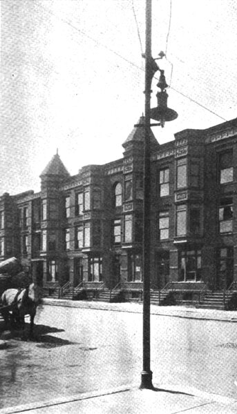
In built-up communities and in the vicinity of railroad yards where space is limited the steel structure takes the form of a tubular or lattice-work pole. Tubular poles are used chiefly where appearance is of prime importance, as in street lighting in resident districts and in the support of trolley lines on important business streets. A neat and inexpensive pole used for street lighting in Chicago appears in Fig. 2. These poles are not commonly used in sizes higher than 30 feet from the ground or larger that 6 to 7 inches at the base. Where stronger and higher poles are required they are built up into a lattice-work from standard shapes of rolled steel.
| |||
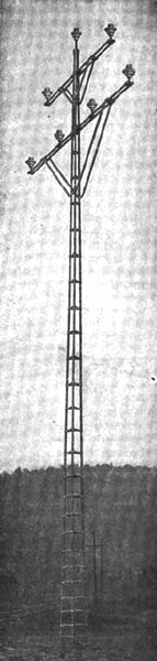
| Fig. 3.Tripartite Pole. Made by the Franklin Steel Co., Franklin, Pa. |
| |||
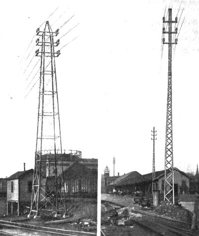
| Fig. 4.Special Line Structures on the Lines of the Worcester & Blackstone Valley Railway Co. Made by the Archbold-Brady Co., Syracuse, N. Y. |
The Tripartite pole, made by the Franklin Steel Co., shown in Fig. 3, is composed of three rib sections forming a tripod of rigid construction. The small number of parts and simplicity of this pole make it a useful type for some classes of work, and moderate in first cost.
The lattice-work type of pole, shown in Fig. 4, is a good example of the usefulness of this type in taking important lines through a railway yard where space for foundations is limited and opportunity for side guying to support the corner poles is almost entirely lacking. The long spans are made safe by the rigidity of the structure which holds the lines taut and reduces to a minimum the possibility of wires coming down across the tracks. This class of construction has been used very generally in the electrification of railroad terminals and in similar important service in thickly settled communities. On cross-country lines where a private right-of-way is owned, and straight-of-way runs are frequent. steel tower construction with a broad base has a number of advantages and has been considerably used.
The line insulator being the most vulnerable point in a transmission structure, it is desirable to have as few points of support as possible. Hence, by making the spans very long, the number of points of support is reduced, and thereby the opportunity for high potential stresses to puncture insulators is minimized. Where it is common practice to space poles from 125 to I50 feet apart in the construction of wooden pole transmission lines. it is possible to adopt spacings of 500 to 600 feet with steel tower lines, thus making only about one-third as many points of support as would be required with a standard pole line.
The use of long spans requires structures of greater height on account of the greater sag which must be permitted in the line. This extra cost, however, is largely offset by the smaller number of towers required. It has been shown by calculation that with greater rigidity in the transverse direction than in the direction of the line.
| |||
| Fig. 5.Steel Tower for Guanajuato Line in Mexico. Made by the Aermotor Co. of Chicago. |
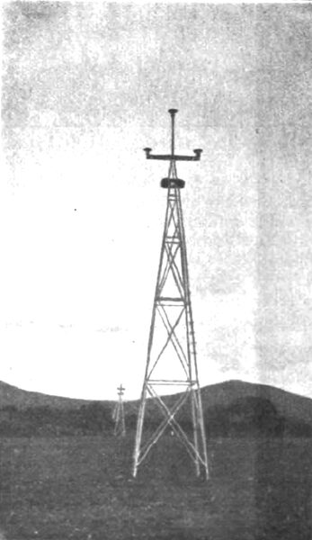
The earliest towers were those installed about the year 1903 for the Guanajuato line in Mexico, which were manufactured by the Aermotor Company in Chicago. These towers, which are illustrated in Fig. 5, were developed as the result of experience with towers built for windmill purposes. Windmill designs were modified to carry transmission line supports, and tests were made to determine their strength before the final design of the tower was settled upon. They have been in successful service for about 9 years.
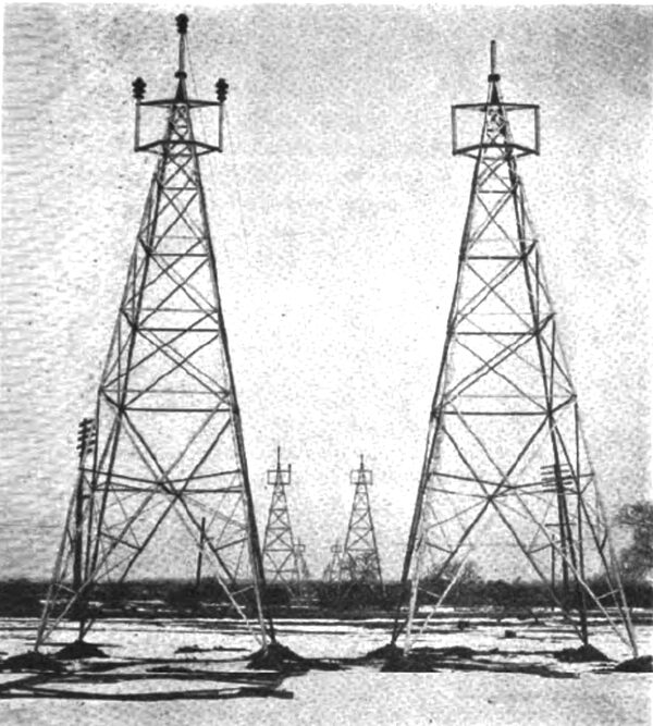
| |||
| Fig. 6.Steel Towers on the Niagara, Lockport and Ontario Power Company's Line Between Lockport and Buffalo. |
| |||
| Fig. 7.Steel Tower for A 100,000-Volt Line of the Commonwealth Power Co. in Michigan. Made by the Aermotor Co., Chicago. |
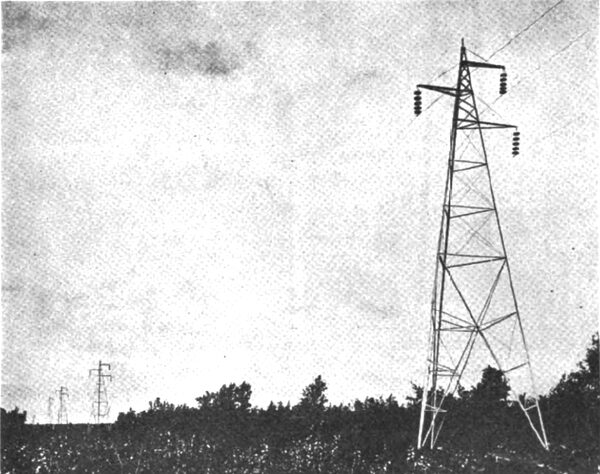
The windmill type of tower is designed to take the strain in any direction, and is, therefore, specially well adapted for use at corners or angles where there are heavy stresses through the change in direction of the line. Later experience with towers used in transmission work has led to some modifications which are well illustrated in Fig. 6, which shows two of the towers on the Niagara - Lockport and Ontario Power Companys line between Lockport and Buffalo. The base of these towers is broader than in the earlier designs, and they were tested with a strain of 5,000 pounds in any direction on the insulator pins, and 15,000 pounds in any. direction at the apex of the tower. A still later design of the Aermotor Company is shown in Fig. 7, in which the support is in the form of a tripod, and which is designed for the suspension type of insulators. This is the first tower designed for a 100,000 volt line, and is in use by the Commonwealth Power Company in Michigan.
This tower was designed to withstand a horizontal load of 3,000 pounds, applied at the middle cross-arm in any direction. The open design at the base of this tower is advantageous where towers are installed through farm lands, as it permits the tilling of the ground around and under the tower, or, if desired, the use of the ground for grazing purposes.
Similar types of towers have been developed by the Riter-Conley Co., the Archbold-Brady Co., and several other American manufacturers.
| |||
| Fig. 8.Flexible A Frame Transmission Structures on Lines of the Fulton County Gas & Electric Co., Gloversville, N. Y. Made by the Archbold- Brady Co., Syracuse, N. Y. |
A flexible type of tower for use in straight sections of tower lines, as developed by the Archbold-Brady Co., is shown in Fig 8. This type of tower is very rigid in a direction sidewise to the line, but has sufficient flexibility to longitudinal strains to permit the structure to adjust itself to a broken wire, and thus relieve a portion of the unbalanced strain caused by the parting of one of the conductors. It is customary where such towers are used, to install a non-flexible, self-supporting tower of the corner type at intervals of about one mile in each straight-of-way section of the line. This is necessary to guard against the entire line being thrown down by all of the wires being parted simultaneously.
This protection can be still further increased by a system of longitudinal guys placed at every third or fourth tower if further security is considered necessary at exposed points.
The flexible type of tower permits a considerable saving in the cost of the structure as compared with an entire line of self-supporting towers, and has given satisfactory service in European countries as well as in the United States.
INSULATORS
The insulator is perhaps the most important detail of an overhead high-tension line. Upon its reliability depends the reliability of the service rendered by the line to a greater extent than on any other detail of the equipment. The fracture of an insulator may ground the line, causing its circuit breaker to open up immediately; or it may slowly burn the cross-arm, damage the pole, and perhaps burn the wire so badly that it is parted, thus interrupting the service.
Much attention has, therefore, been given to the development and scientific study of the materials, formulation, and testing of high-tension insulators as the potentials at which transmission lines are operated have increased. The art of the manufacture of porcelain has been correspondingly developed so that structures and shapes which could not be made in porcelain in the early years of the development are now worked out with a high degree of uniformity and reliability.
Glass served its purpose very satisfactorily for many years on the telegraph lines and distributing lines up to 5,000 volts where its low cost is still in its favor. The earliest high-tension lines were built on glass insulators, and some of these insulators are still in service on lines working up to 40,000 volts. It is found, after a few years, however, that the stresses set up in glass by rapid changes in temperature caused many of them to fail, resulting in entirely too high a percentage of line interruptions from this cause.
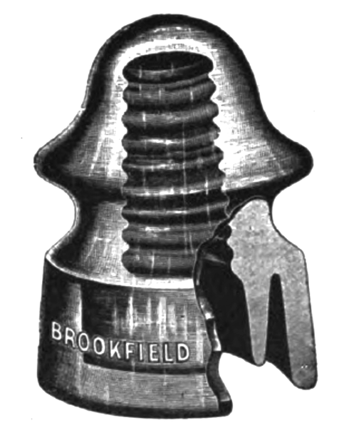 |
| Fig. 9.-Double Petticoat Insulator. Made by the Brookfield Glass Co., New York |
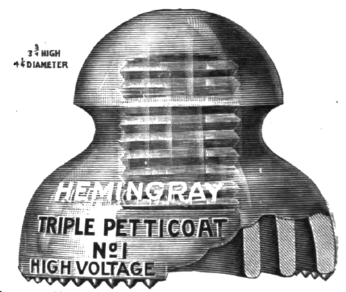 |
| Fig. 10.Triple Petticoat Glass Insulator. Made by the Hemingray Glass Co., Muncie, Ind. |
The use of glass is, therefore, now limited to smaller sizes of insulators, such as those made by the Brookfield Glass Co, of New York (Fig. 9), and the Hemingray Glass Co., of Covington, Ky. (Fig. 10), which are sufficiently rugged to prevent leakage due to expansion and contraction at times of sudden changes in temperature.
Line insulators must be proportioned according to the voltage which they are to carry. An insulator must prevent leakage across the surface from the line to the pin or a direct flash over from the line wire to the support. The tendency for the electricity to leak over the surface is met by shaping the insulator in the form of inverted cones, called petticoats, the shape of which is made such that the under sides cannot become wet during the most severe rain storm. The tendency for the electricity to are over to the pin is counteracted by making the top petticoats of the insulator broader and flatter than the lower petticoats, thus securing a maximum striking distance.
The tendency to flash-over exists in all transmission systems at times of internal high-tension surges as well as during lightning storms. It is one of the most difficult problems with which the designer of insulators has to cope.
Porcelain insulators may be classified in a general way in three divisions: (a) single-piece, pin type; (b) multi-piece pin type; (c) suspension type.
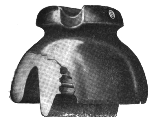 |
| Fig. 11.O-B Insulator No. 9403 for 6,600 Volts. Made by the Ohio Brass Co., Mansfield, Ohio. |
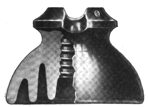 |
| Fig. 12.O-B Insulator No. 10044 for 13,000 Volts. Made by the Ohio Brass Co., Mansfield, Ohio. |
Single piece insulators, pin type, are used on voltages up to about 15,000. They are made for use with a side tie-wire for the smaller sizes of conductors, as shown in Fig. 11, which is a 6,600-volt Ohio Brass Co. insulator, and with a top groove for the larger sizes, as shown in Fig. 12, which is a 13,000-volt OB insulator. The top groove insulators are also provided with side grooves for the tie wires, and this permits the side tie to be used at corner poles or with smaller sizes of conductor if desired.
Multi-piece insulators are made in two, three, and four pieces, which are separately molded and fired, and are afterwards cemented together. This is necessary with the larger sizes. in order to guard against the possibility of internal cracks, which would weaken the dielectric strength if it were attempted to mold and fire the insulator in one piece. It also permits a careful inspection to be made of each piece, thus insuring greater uniformity.
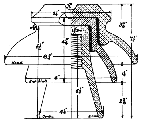
 |
| Fig. 13.No. 408-B Pin Type Insulator for 30,000 Volts. Made by the Locke Insulator Mfg. Co., Victor, N. Y. |
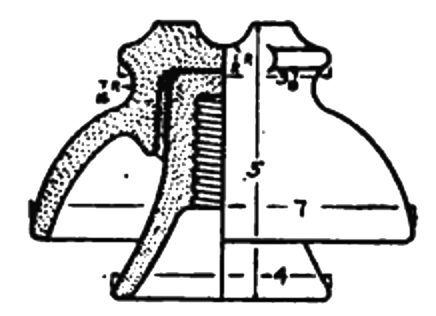 |
| Fig. 14.No. 2019 Pin Type Insulator for 23,000 Volts. Made by the Locke Insulator Mfg. Co., Victor, N. Y. |
The two-piece insulator is made for voltages of from 20,000 to 30,000. It is made in various forms, the 30,000-volt Locke No. 408-B insulators representing one extreme, the 23,000-volt Locke No. 2019 another. The 408-B insulator, shown in Fig. 13, is flat across the top, long in the shank, and has a striking distance of jé inches. It weighs about 5 1/2 lbs. The long shank covers more of the pin than does the No. 2019, shown in Fig. 14. This insulator has a striking distance of 3 inches, and weighs about 4 lbs. The type represented by the 408-B insulator is somewhat more exposed to mechanical injury on account of its broader exposure. If either piece of the insulator is broken, the danger of the line being grounded is greater than in the No. 2019 type, in which only one member is much exposed, and the general shape is more rugged. However, each type has its advantages, and various other designs have been worked out which strike a mean between these extremes.
 |
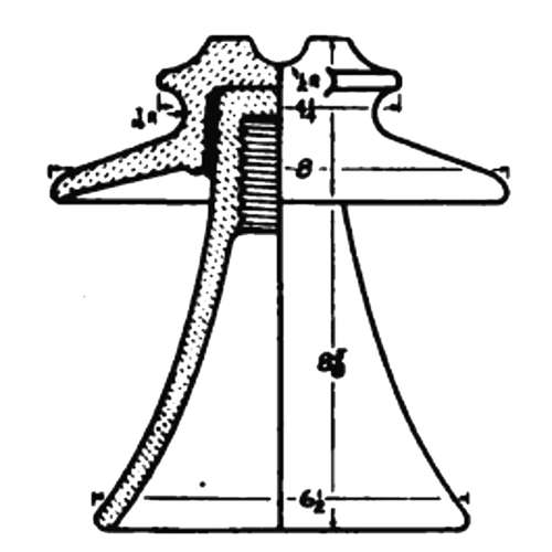
| Fig. 15.33,000-Volt Insulator. Made by the R. Thomas & Sons, East Liverpool, Ohio. |
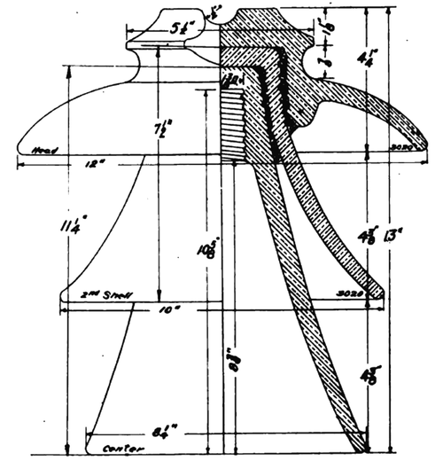 |
| Fig. 16.50,000-Volt Insulator. Made by the R. Thomas & Sons, East Liverpool, Ohio. |
Insulators made for voltages from 30,000 to 50,000 are made in three pieces on account of the increased size and weight. The form shown in Fig. 15 is a 33,000-volt insulator, and that shown in Fig. 16 a 50,000-volt R. Thomas & Sons insulator. The striking distance of the 33,000-volt insulator is about 4 3/8 inches and it weighs about 8 lbs., while that of the 50,000-volt insulator is about 9 inches, its weight being about 17 lbs.
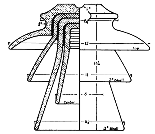 |
| Fig. 17.No. 360 Pin Type Insulator for 66,000 Volts. Made by the Locke Insulator Mfg. Co., Victor, N. Y. |
Four-piece insulators are used for 60,000 to 70,000 volts where the pin type of insulator is used. The Locke insulator, shown in Fig. 17, is designed for 66,000 volts. It has a striking distance of 10 inches and weighs 35 lb. Similar types of insulators are made by the Pittsburg Insulator Co. and others.
 |
| Fig. 18.No. 2006 Suspension Insulator for 10,000 Volts. Made by the Locke Insulator Mfg. Co., Victor, N. Y. |
 |
| Fig. 19.No. 2080 Suspension Insulator for 22,000 Volts. Made by the Locke Insulator Mfg. Co., Victor, N. Y. |
 |
| Fig. 20.No. 2019 Suspension Insulator for 30,000 Volts. Made by the Locke Insulator Mfg. Co., Victor, N. Y. |
In recent years the suspension type of insulator has been employed in connection with the development of transmission at voltages above 75,000. The suspension type of insulator has many advantages over the massive pin type of insulator required for higher voltages in that several can be hung in series with each other, thus giving a larger factor of safety at a small additional expense and a more flexible type of line construction. The difficult mechanical problem of supporting the weight of heavy insulators and the strain of a transmission cable on a pin is eliminated, and the problem of the support of the conductor is in every way simplified. Various types of suspension insulators are shown in Figs. 18 to 20, that in Fig. 18 being designed for 10,000 volts per unit, and Fig. 20 for 30,000 volts per unit.
 |
| Fig. 21.O-B Strain Insulator No. 9897 for 10,000 Volts. Made by the Ohio Brass Co., Mansfield, Ohio. |
 |
| Fig. 22.O-B Strain Insulator No. 9000 for 35,000 Volts. Made by the Ohio Brass Co., Mansfield, Ohio. |
STRAIN INSULATORS
At corners and dead ends where heavy strains are placed on pins. the security of the line may often be made much greater by the use of a strain insulator of the type shown in Fig 21. This is supported by a vertical rod between two cross-arms, and, therefore, does not depend on a single pin. These insulators are very useful in supporting lines in very long spans, and at river crossings, and at such points they are often arranged so that several insulators divide the strain between them.
PINS
Wood pins are commonly used for all ordinary distribution lines and for transmission up to 10,000 volts. Locust is the most durable and the strongest wood for pins, though catalpa and a few other southern woods have been used with good results.
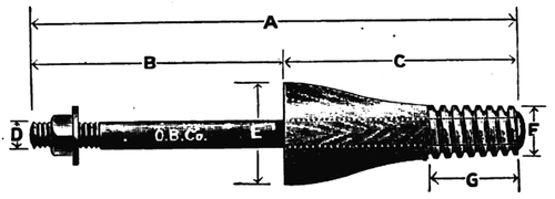 |
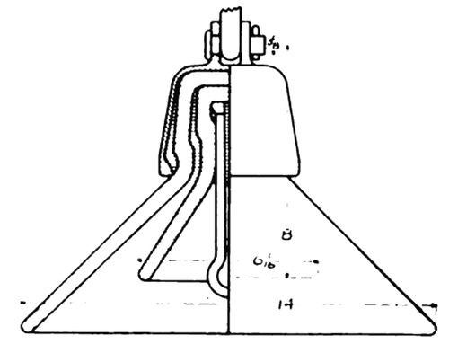
| Fig. 23.Wood Pin With Steel Bolt. Made by the Ohio Brass Co., Mansfield, Ohio. |
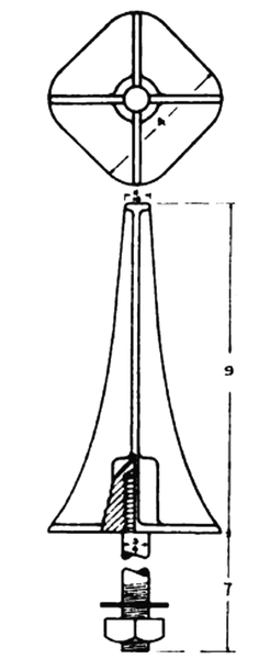 |
| Fig. 24.No. 100 Insulator Pin. Made by the Locke Insulator Mfg. Co., Victor, N. Y. |
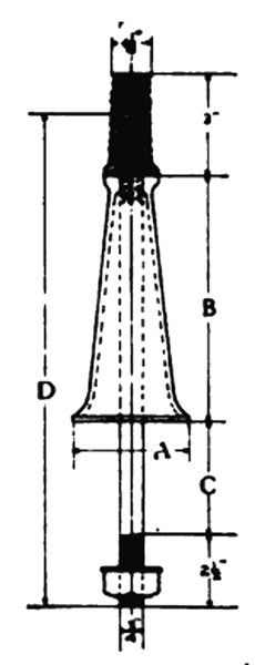
At the higher voltages the insulator is so tall that the pins must be lengthened as the voltage is increased. This necessitates a large diameter at the shank of the pin, and larger timber for cross-arms so that the ordinary 1 ½-in. by 9-in. pin of the 5,000-volt line becomes a 2-in. by 18-in. or more pin in a 30,000 or 40,000-volt line (Fig. 23).
For this reason and because of the tendency of wooden pins to become charred if an insulator proves defective, many engineers prefer to use iron pins. These take various forms according to the size of the insulator.
 |
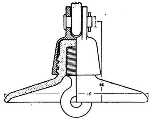
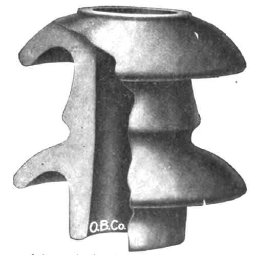
| Fig. 25.Lee Type Cross-Arm Pin. Made by the Ohio Brass Co., Mansfield, Ohio. |
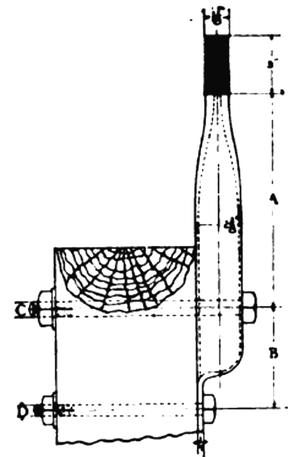
A common form consists of a malleable casting with four ribs, the top of which is cemented into the porcelain thimble on top which is cemented into the porcelain at the factory and is attached to the pin by screwing a central bolt up into the thimble as shown in Fig. 25.
Another device designed to avoid the burning of pins consists in making the shank of porcelain, with a threaded wooden tip mounted on a steel bolt as a center.
The type of pins which have a steel bolt going through the arm may be used with smaller cross-arms than all wood pins which require a larger hole.
 |
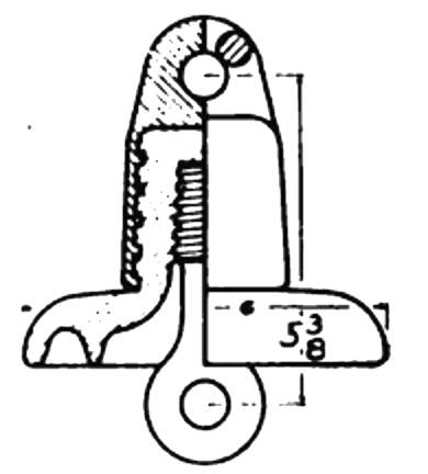
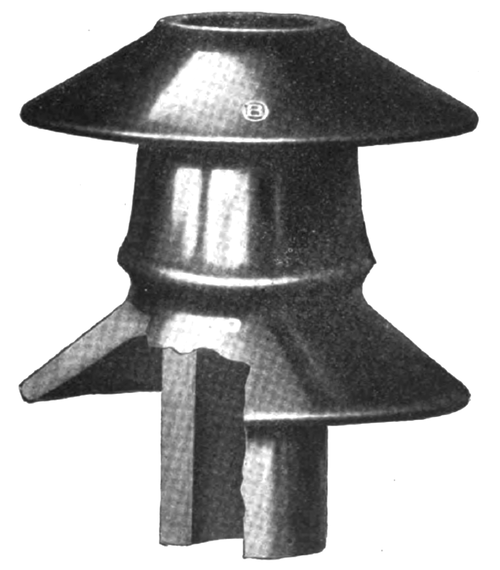
| Fig. 26.Lee Type Pole Top Pin. Made by the Ohio Brass Co., Mansfield, Ohio. |
The 5/8-in. bolt will, however, sometimes bend under heavy strain, leaving the insulator at an angle and perhaps endangering the security of the tie connection to the conductor. The type of pin shown in Fig. 26, which has a saddle at the top of the arm, provides a broader support for the strain and largely obviates the difficulty.
Various special forms of pins are required in some cases such as pole top pins designed for direct attachment to the pole, strain insulator pins, and other.
[Article No. 2 of this series will be published in the April issue of the ELECTRIAL RECORD.]
