[Trade Journal]
Publication: The Journal of Electricity
San Francisco, CA, United States
vol. 1, no. 5, p. 107-110, col. 1-2
The Nevada County Power Transmission.
THAT the installation of electric power transmission plants in the mountainous mining regions of the Pacific Coast is attended with many unforseen difficulties other than electrical, is shown in the interesting, plant now being erected in California by John Martin under contract for the Nevada County Electric Power Company. So typical is this undertaking of electric installations in mountainous countries, that a description of the means resorted to for handling the heavy machinery will be both interesting and instructive.
| |||
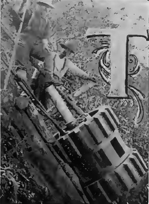
| Figure 1. -- on the Slide. |
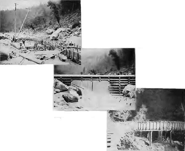
The plant under consideration is to be driven by water power, mainly derived from the south fork of the Yuba River, at a point 18,400 feet above the site of the power house. At this point a cribbed log dam, twenty-six feet high and seventy-eight feet wide, illustrated in Figure 4, has been erected. Inasmuch as the Yuba River at this point constitutes a torrential stream during the winter season, the utmost care was necessitated in the erection of a log dam to withstand the floods of each winter; accordingly a site walled in by solid granite was selected for the dam and the diverting flume shown in Figure 3 was built to carry off the water from the natural bed of the river, in order that each log might be bolted to bedrock and to each other. From the completed dam is run the flume shown in Figures 3, 4 and 5. This is five by six feet in size and ice a capacity of 5,950 miners’ inches. One and one-quarter million feet of pine lumber was used in its construction, which consumed the labor of 110 men for four months. Continuing, as the flume does, mainly along the granite bluffs confining the river, its construction was a task of great magnitude, involving the exercise of meek engineering skill and risk of life on the part of the workingmen. The construction of the dam and flume was done under the supervision of Mr. Alf. Tregidgo, who from the outset has been fore-moat in the undertaking.
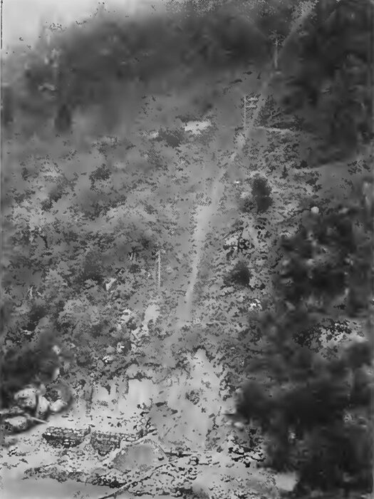
The flume terminates immediately above the power house on an exceedingly steep incline known as “The Slide," which, together with the power-house site, is illustrated in Figure 2, giving the water a head of 206 feet. From the penstock of the flume steel-riveted pipes, 320 feet in length, are to he carried down, the first 120 feet being of forty-eight-inch pipe, and the second and third 100 feet being forty-four and forty-two-inch pipe respectively. The pipe line terminates in the large steel receiver (Figure 8), which wilt supply water to the two seta of Pelton wheels operating the generators. This receiver is nineteen feet in length and forty-eight inches in diameter, weighs approximately four tons, and constitutes the largest though not the heaviest piece of apparatus used.
| |||
| Figure 2. -- the Slide and Power-House Site. |
As indicated, the power is derived from two sets of Pelton water wheels, each of which consists of two, thirty-four and one-half-inch Pelton wheels, direct connected
bed, rock through which were run thirteen three-quarter-inch iron bolts that had previously been sulphur-cemented into holes that had been drilled into the granite to a depth of eighteen inches. Bolted by this means to the concrete are three timbers dressed down to eight by ten inches that have previously been tarred and wrapped with two layers of P. & B. roofing paper and finally imbedded in cement. The holding-down bolts for the bed plates of the generators are lag screws, which in turn are sulphur-cemented into the wood timbers, thereby attaining the highest possible insulation resistance to earth. The generators will he provided with two Crocker-Wheeler multipolar exciters, each having a rating of five kilowatts. These are to be belt-driven by independent Pelton wheels, and either will be of ample capacity to excite both generators.
| |||
| Figures 3, 4 and 5. -- the Site of the Dam and Dicending Flume, the Completed Dam and A Portion of the Flume Line, Respectively, of the Nevada County Electric Power Company. |
No step-op transformers are to he used, as the generators will deliver two-phase current to the line at 5500 volts. The pole line is very close to eight miles length and caries eight No. 3 B. & S. bare copper wires on two crass-arms, each pole being gained for two additional cross-arms. Thirty-feet round peeled poles are used, and throughout the entire line a sixty-foot clearance has been cut fur the pole line through the timber and brush. The line loss is le be approximately 5 per cent, and the plant will be operated at 16,000 alternations per minute. Triple petticoat top-grooved porcelain insulators, five inches across the bell and manufactured by F. M. Locke of Victor, New York. are being used throughout.
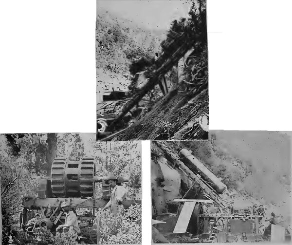
The machinery for the plant was transported by rail to Nevada City, Cal., which is a little less than five miles from the power house, and from the outset difficulties of an unusual character were encountered. The scene of operations is in the midst of that portion of California which was the venter of hydraulic mining activity until the anti-debris agitation put a stop to that mode of mining. The roads are, or rather were at the time when the transportation of the machinery was commenced, in practically the same condition as existed during the early mining days. They were exceedingly bad thoroughfares laid out over the shortest routes, almost regardless of grades. Whole mountain sides had been washed away by the hydraulic miners, and the rush and anxiety attendant upon the search for the precious metal forestalled all attempts at road-building, with the result that the highways were impassable for heavy machinery. The wagon road, such as it was, did not reach within nearly two miles of the site of the power house, which compelled the building of a road over an exceedingly mountainous country, in addition In which the contractor found it necessary to partially reconstruct the old wagon road to the extent of clearing it of rocks and boulders, and widening it sufficiently to admit the passage of heavy machinery. This was drawn to the top of the slide by means of teams varying from six to twelve horses each, according to load. Each of the Stanley generators consists of six pieces weighing approximately five tons each, the heaviest piece being the inductor, which weighs 11,200 pounds, and which proved to be the most difficult piece to transport. A special truck constructed for it, and despite the unusual precautions taken a break-down occurred (Figure 6), and although the blockade thus occurring could be cleared out within a day with the appliances at hand, the urgencies for preventing delay in transporting other machinery were so great that a new road was built around the break-down. The character of the country through which this road was constructed is clearly shown in the illustration and the growth of underbrush, cactus and small pine and scrub oak trees was so dense as to render road building a serious task. Many of the grades on this improvised highway were so steep as the necessitate lowering the trucks down by means of block and tackle, yet despite this the machinery reached its destination without having suffered the slightest injury.
| |||
| Figures 6, 7 and 8. -- Illustrating Some Difficulties Encountered in the Installation of the Transmission Plant of the Nevada County Electric Power Company. |
The greatest obstacles to be surmounted were those encountered in lowering the machinery down the mountain side, shown in Figure 2, in which the power-house site appears upon the river bank. In this illustration photography fails to bring out much more than a suggestion of the steepness of the slide. Within a horizontal distance of probably one-half a mile the mountain rises to an elevation of about 1700 feet above the river level. The first 400-feet drop from the top may he reached by wagon road. Continuing downward, the next 400 feet is an angle of twenty-five degrees, and the next 600 feet is an angle of thirty-two degrees. Then follows about eighty feet of thirty-five degree declivity, and finally a further drop of about 220 feet is made to the power-house site at an angle of thirty-nine degrees, down which not only all machinery for the plant has been lowered, but upon which the pipe line has to be laid and securely anchored.
The means by which the machinery has been lowered down the slide are those familiarly applied in house moving, and which is to termed "snubbing." Each piece of machinery is mounted singly upon a heavy log sled made in the most substantial manner, and secured thereto by means of chains, ropes or in such other manner as will prevent slipping. Generally three 1-1/2-inch manilla ropes are then secured to the sled and machinery, with such rope being wrapped several times around a tree trunk, and a man being stationed at each of the three trees to control the ropes. The load is then lowered gradually by slacking the ropes or "snubbing" them as in house moving.
The illustrations given convey a suggestion of the methods used in overcoming the barriers presented in this interesting installation, and it is worthy or note that despite the many and unforeseen difficulties encountered the work of installation has progressed without mishap or delay, and the plant will without doubt be in operation by December 10th.
The mechanical features of the work have been placed under the direction or Mr. T. J. Benny, and the entire electrical equipment has been erected for Mr. Martin through the electrical engineering of Mr. E. E. Stark, of the Stanley Electric Manufacturing Company, whose apparatus is being used throughout.
The plant now being erected constitutes the initial installation, and it will therefore be enlarged as necessary to meet future demands. Probably seventy-five per cent. of the capacity of the plant will be absorbed in the delivery of power to the mining industries of the vicinity, and already sufficient business has been contracted for to more than defray all fixed charges.


