[Trade Journal]
Publication: The Journal of Electricity, Power and Gas
SAn Francisco, CA, United States
vol. 14, no. 11, p. 439-452, col. 1-2
High Potential Long Distance Transmission and Control. (1)
BY F. G. BAUM.
[WITH AN INTRODUCTION, BY THE EDITOR, ON THE DE SABLA POWER PLANT.]
PREFATORY to the invaluable paper presented by P F. G. Baum to the International Electrical Congress, and which follows, it is of interest to briefly detail some of the important features of the de Sabla power plant of the Valley Counties Power Company, which Mr. Baum describes, with particular reference to its most excellent interior high tension switching arrangements.
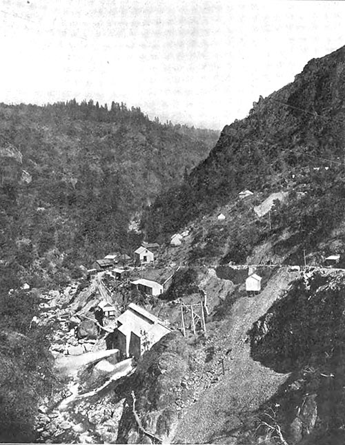
Eight miles by way of the road above the Centerville power house of the Valley Counties Power Company, and which in turn is sixteen miles east by southeast of Chico, and in Butte County, California, and so far down in the narrow canyon of Butte Creek that the sun reaches it but five hours a day at the most, is situated the de Sabla power house. During its construction the plant was known as Nimshew, the name of an Indian tribe which, though now extinct, formerly occupied the section of the country which the plant and its water system embraces. In design the installation is plain and modest, but potent in every detail, and among its most striking peculiarities are the high head under which its wheels are operated, its extreme simplicity of arrangement, its mammoth water wheel and generator unit, and its seemingly perfect high tension arrangements.
| |||
| The De Sabla (Erstwhile "Nimshew") Power House and Environs. |
Nimshew, the postoffice for the plant, is an old settlement at the top of the hill within two miles of the reservoir, whence a three and one-half mile road that forms a boulevard in the perfection of its construction and in the grandeur of its course down into the canyon, leads to the power house. A direct route thereto is by way of the trail, which goes down almost precipitously to the power house in a route which, though pipe line, which has a capacity of about 9,000,000 cubic feet of water, is confined by an earth-filled dam having a height of fifty-four feet above the head-gates of the main pipe lines. This reservoir was designed to safeguard the ditch and to tide over the plant under peak load conditions. The source of water supply is unfailing with reference to the installed capacity of the plant, in view of which no effort is made toward conserving the water for use during dry seasons.
| |||
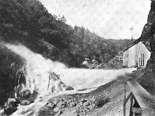
| A Single Three-Inch Jet in Open Discharge Under A Static Head of 1560 Feet. |
Two pipe lines lead from the reservoir to the power house, the first of which has been in operation for a little over a year. This line is 6003 feet in length, the upper section of which, amounting to 4400 feet, is laid on a hydraulic grade of twenty-eight degrees from the reservoir to a location known as Common Point. This first section is all of steel riveted pipe running from nine-sixteenths of an inch to No. 10 in thickness, the pressure at its lower end being 350 pounds per square inch. From Common Point section No. 2 continues down on to the power house at a distance of about 1600 feet further at a gradient of thirty-two degrees fifteen minutes. Approximately one-half of this distance is tunneled, and from Common Point lap welded flange tubing is used through to the power house. Its thickness tapers from one-half inch at Common Point to three-quarters of an inch at the lower end, and the last 190 feet has been tested to a hydrostatic pressure of 1000 pounds per square inch. The diameters used on these pipe lines are thirty inches inside measurement for all riveted pipe and thirty inches outside measurement for all lap welded pipe, with the exception of a few trestles which are built on standard railroad specifications, and the longest of which is 180 feet, the entire pipe line being either buried in a trench or run through tunnels that have since been filled in.
Pipe line No. 2 is practically a counterpart of the foregoing, in so far as the specifications of the pipe itself are concerned, the main difference between them resting in the fact that No. 2 is run almost continuously in tunnels. Beginning at the point where the tunnel enters the power house this tunnel is run into the mountain at a grade of one foot per rod for a distance of 250 feet, whence it continues upward at an incline of thirty-three degrees fifteen minutes for 1568 feet, whence it is carried to the reservoir along a course parallel to pipe line No. 1.
These pipe lines are provided with the latest type of six-inch air valves, air cock release valves and blow-offs and expansion joints, together with an eighteen-foot stand-pipe for each at the reservoir. The joint in the lap welded pipe is of the type designed by W. R. Echart and originally installed at Electra, the only difference being that in the de Sabla plant a rubber core of a larger diameter is used. Pipe line No. 2 is anchored at every joint in the tunnel, while in the 1600 foot section of pipe line No. 1 there are thirty-three anchorages, one of which alone contains 100 tons of masonry. When it is known that the lower ends of these pipe lines must sustain a thrust of about 750 tons, the necessity for stalwart work in the direction of anchorages becomes apparent. Under normal conditions of load the nozzles discharge some 3000 miners inches of water, the velocity of which in the pipe line is a little less than nine feet per second.
| |||
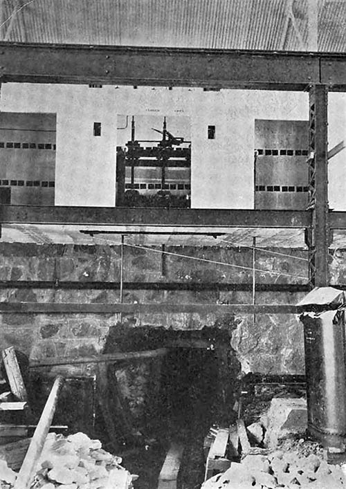
| A Perspective View of the High Tension Switching Gallery of the De Sabla Power House. |
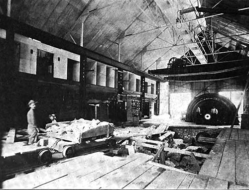
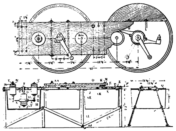
A bench blasted from the solid rock gives footing to the power house which consists of a steel and corrugated iron structure, sealed with corrugated iron. In the clear it measures 107 feet by fifty feet four inches, and along its peak is run a lighting and ventilating turret. In the center of the side of the building nearest the creek is built a small bay eight feet deep and thirty-seven feet long in which is contained the exciter sets. Two |forty-ton traveling cranes of Cyclops manufacture stand the width of the entire building.
| |||
| Transformer Disconnecting Switches , Showing High Tension Busbar Compartments and Lever Mechanism. |
The plant was placed in service on October 22, 1903, with two 2000-kilowatt generators in operation, and on August 22nd of this year its third unit, consisting of a 5000-kilowatt generator, was placed in regular service. The water wheels are of the Doble type and build, two of which have a capacity of 3500 horsepower each and the capacity of the third wheel unit being 7500 horsepower. In the wheel units first installed the buckets are mounted on a rolled steel disk having a diameter of ten feet ten inches, and this disk is supported on a hollow sixteen-inch shaft that in turn rests in bearings that are five feet five inches in length. These bearings are cooled by a water circulation and are supplied with oil under pressure. Each wheel of units Nos. 1 and 2 overhangs a concrete pit that is four feet wide and seven feet four inches deep, and the wheel casings stand eight feet six inches above the floor line. A single nozzle is used under each wheel. It is of the needle regulating and deflecting type, actuating by a Lombard type D governor. Water for the operation of these wheels is taken from pipe line No. 1, which separates into two branches for the respective wheels within the station. It enters the nozzles at a depth of twenty-inches below the floor line through a Doble piston gate valve with fourteen-inch openings. This gate valve is operated both ways hydraulically by turning a hand-wheel connected to a three-way valve. The water is applied to the wheels under an effective pressure of 1534 feet, the gauge standing at 666 pounds per square inch. The wheels, which are mounted direct on the end of the generator shaft, run at a speed of 240 revolutions per minute. A six-inch branch from the main pipe line at the curve carries water to the exciter wheels, each of which is controlled by a three-inch gate valve.
| |||
| Stirling Line Disconnecting Switches at the De Sabla Power House. |
Lovers of the spectacular will ever find something to excite their admiration, if not awe, in the discharge of a five-inch stream of water under a net head of 1560 feet, giving a pressure of over one-third of a ton per square inch. This means that with a nozzle five inches in diameter, the static strain against this area is above seven tons, while the velocity of the stream is over 18,000 feet per second, or at the rate of three and one-half miles per minute. An idea of the appearance of such a stream is given in the illustration on page 440. The visible portion of the jet as appears in the photograph has a length of about 150 feet before reaching the wall of rock on the opposite side of the creek, nevertheless the stream shows no influence from gravity, for it is as straight as though laid out with instruments of precision. The bombardment it gives the wall is simply terrific, and the atmosphere for a score of rods around is filled with spray that falls as rain, making merry cascades which flood the mountain sides, and as for the noise, it is a succession of ripping peals that deafen and strike with awe.
Pipe line No. 2 is used exclusively for the operation of the 5000-kilowatt unit, which is driven direct by a single Doble water wheel that under overload conditions delivers 5500 kilowatts at the switchboard by the single jet of water. Of the details of this wheel, however, more will be published in a special article which will be devoted to the subject in an early issue of THE JOURNAL.
The exciter sets are of the Theberath combination type, consisting of a water wheel, an induction motor and a direct current generator mounted on a single shaft and first used with such pronounced success at Colgate. These sets are four in number, and each consists of a single eighteen-inch Doble water wheel, a seventy-five horsepower, three-phase, 2300-volt General Electric induction motor and a forty-five-kilowatt multipolar direct current General Electric generator wound to deliver sixty volts with no compounding. These three units of a set are direct coupled and run at a speed of 720 revolutions per minute. Each set is capable of exciting two 2000-kilowatt generators and the one 5000-kilowatt unit, and obviously in case of failure of the water wheel the induction motor which is always coupled in parallel with the generator busses will supply instantly ample power for the operation of the exciter.
Beyond the power house, along the foot of the bluff which rises precipitously as the background to the photograph reproduced on page 439 runs Indian Spring Ravine, which carries besides its own water that of several other springs of lesser note, together with such overflow as may come from the waste weir of the reservoir upon the mountain above. This ravine supplies ample water for cooling the transformers and generator and water wheel bearings and shafts, as well as affording fire protection. From this ravine is also filled a 10,000 gallon tank which, well housed, stands up on the hillside at an elevation of 180 feet above the power house, to which it is connected by about 650 feet of entrenched six-inch pipe. Not far from this tank is a corrugated iron building containing two iron tanks, one of a capacity of 1000 gallons for the storage of transformer oil, and the other, which holds 1500 gallons, for lubricating oil. These tanks are at an elevation of about seventy feet above the power house. All oil is handled either by gravity or by pumping. That from the bearings drains into a filtering reservoir outside the station at its lower corner, whence it is pumped back to the lubricating oil tank on the hill, and to empty a transformer case merely means to pump the oil back into the transformer main leading from the hill.
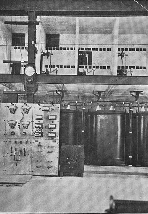
The statement has already been made that the de Sabla power house is of extreme simplicity, especially in the matter of its electrical equipment. Three generating units, a single panel switchboard for each, an exciter panel, a three panel main switchboard, the necessary transformers and the disconnecting switches up in the fireproof gallery, constitute the entire electrical paraphernalia necessary for handling a normal load of 9000 kilowatts. As to details, each generator panel, placed convenient to its respective machine, carries two voltmeters, two ammeters, two indicating wattmeters, two recording wattmeters, all of the Thomson type, besides a synchronizing lamp and three-pole oil switch by means of which the low tension side of the set of transformers for the respective machine is thrown in parallel with it. The main switchboard carries three panels; the upper half of the first panel carries a synchronizing lamp, an ammeter, a voltmeter and a field ammeter for each of the two 2000-kilowatt generators, so as to give a reading for one phase of each machine. The lower half of this panel has four double-pole single-throw knife switches, by means of which the fields of either machine may be thrown on either exciter. This half panel also carries near the top two two-button plate pushes for running the Lombard governor on the respective water wheels either fast or slow, a result which is accomplished by means of a small electric motor that is one-geared to the valve stem of the governor. The panel also contains in its upper half hand wheels for controlling the field resistances of each 2000-kilowatt generator.
The second panel is essentially an exciter panel. Its upper half contains a Thomson static voltmeter and am-meter, as well as a rheostat for each exciter, and these, together with a recording voltmeter and a two-point switch therefore, completes its equipment. Below, the remaining half panel carries two small double-pole single-throw knife switches for the fields of the respective exciters, a large double-pole single-throw knife switch for paralleling the exciters, and a triple-pole oil switch for handling the 2300-volt three-phase current with which the respective induction motors of the exciter combination sets are always at least under excitation. No possible arrangement could be more simple nor more efficacious. Similar arrangements are provided on the third panel for the control of the 4000-kilowatt unit.
 |
| High Tension Line Switches in Construction at the Black Diamond Substation. |
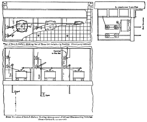
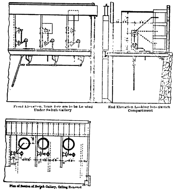
The transformer and high tension gallery section is to the writers mind the most perfect piece of engineering construction to be found in California. It is contained in a bay which runs along the entire side of the building nearest the mountain. Its depth is eleven feet six inches. Its lower half, or that portion which is on the main floor of the station contains twelve raising transformers, each having a capacity of 840 kilowatts, with 2300 volts on the low tension sides, and wound to deliver either 44,000, 55,000 or 66,000 volts on the high tension side. They now give 66,000 volts or a little over. Immediately over the transformers is the high tension switching gallery, which is absolutely fireproof throughout, the floor being of steel I-beam and tiling construction flushed with concrete and all walls and ceilings being of hollow tiles. The views appearing on pages 440, 441 and 442 show the general appearance of this gallery during construction, and in explanation it should be stated that the gallery is divided into twelve compartments, each of which measures six feet two inches in width by eleven feet in length, the height being ten feet nine inches. Back of the switching compartments and running the entire length of the building are three separate parallel wire ways for the high tension busses. These wireways are each two feet square by a length of 107 feet, and are made of four-inch tiling on their front and back walls with separations of six-inch tiling. A single bus supported on standard Locke 60,000-volt insulators runs through the entire length of each, and to these busses the high sides of the respective transformers are cut in through individual single-pole air-break disconnecting switches which are controlled in gangs of threes by means of a system of levers actuated manually from the floor of the transformer section beneath. The busses reach the line through the intervention of a four-break high tension switch with a Stirling switch for emergency, as described by Mr. Baum, these switches occupying the compartment of the gallery nearest to the point where the transmission line leaves the building.
To complete this superficial description of the plant it is only necessary to state that the 2000-kilowatt units are counterparts of those of like capacity installed at Colgate, and which will be remembered are of the well known S.K.C. inductor type. The 5000-kilowatt unit is also of S.K.C. manufacture, but it is of a revolving field type. It is unique from the fact that the field coils are carried by two three-quarter-inch steel discs instead of the usual spider. These units deliver three-phase current at 2300 volts.THE EDITOR.
F. G. BAUM ON TRANSMISSION AND CONTROL.
In 1900, at the general meeting of the American Institute of Electrical Engineers, I presented a paper giving Some Constants for Transmission Lines, based on measurements made on several transmission linesthe longest that had been built up to that time. Since then I have followed very closely the progress of transmission work, and in this paper I will give the practice and results on what is, and has been since 1900, the greatest transmission system in existence.
The system to which I refer is that of the California Gas and Electric Corporation, which has absorbed the Bay Counties Power Company, the Standard Electric Company of California, the Valley Counties Power Company, the Sacramento Electric, Gas and Railway Company, the Yuba Electric Power Company and the Nevada County Electric Power Company.
The system has continuously in operation about 700 miles of line at 50,000 volts, seventy miles at 40,000 volts and a great many miles at 23,000, 16,000, 10,000 and 5000 volts. The high voltage lines extend from the Sierra Nevada Mountains of California to the Bay of San Francisco, and are thus exposed to all sorts and conditions of weather. In a short time some of these lines will be operating at 60,000 volts. The longest distance to which power is regularly transmitted is 200 miles, most of the power being transmitted 150 miles. The amount of power available on the system is 43,650 kilo-watts, and this will soon be increased by the addition of two 5000-kilowatt generators at Electra. Owing to the large day motor load the peak on the system is not above 25 per cent. of the average load.
In this paper I will give as briefly as possible some simple methods of line calculation, and deal with the methods of controlling the power at the high voltages.
PART ILINE CALCULATIONS.
 |
 |
 |
 |
 |
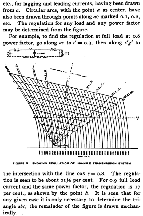 |
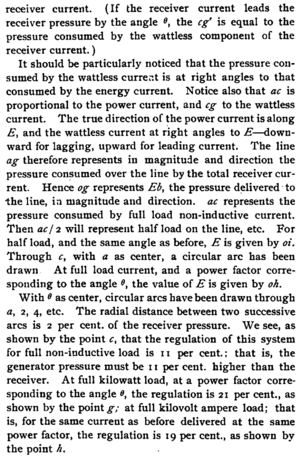
Figure 5 shows the regulation of a 150 -mile, 60 periods per second, three-phase line for any load and any power factor, with 30,000 volts between neutral and line wire, giving 51,960 volts between wires. The power trans mitted is 3000 kilowatts per leg, or a total of 9000 kilo watts The small triangle Kea shows the rise in pressure due to the charging current. The regulation of the line for any load at any power factor is clearly shown. At no load, with 27,500 at generator, we get 30,000, or full voltage, at receiver, or a rise in pressure of 9 per cent. The effect of a synchronous motor load of any character may be determined from the figure.
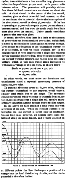
5 . Electrical SurgesWe cannot avoid an occasional short circuit on the high voltage line. These shorts cause a heavy current to flow over the line, and the breaking of this current sets up surges which cause a rise in voltage that may be two to three times the normal operating voltage. The subject has been discussed by C. P. Steinmetz, Dr. A. E. Kennelly and P. H. Thomas. A simple method is here given, the matter of the Pacific Coast Electric Transmission Association, in 1892.
The subject is an interesting one to us, as we have all seen lightning arresters fused on account of the sudden opening of a circuit. I shall attempt to put the matter as briefly as possible, and in such a form that the rise in potential which we may get under the worst conditions may be easily and quickly determined. The most important case of opening a short circuit under load will be discussed.
 |
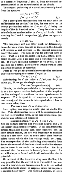 |
 |
 |
PART IIHIGH POTENTIAL CONTROL.
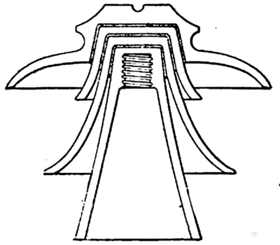
1. InsulatorsWe have on our lines practically every type of insulator manufactured. We have glass insulators, porcelain insulators and combinations of porcelain and glass having from one to four parts. In the mountains and away from the fog, a seven-inch glass does very well on 40,000 volts, but to go from 40,000 to 60,000 requires that the insulator be increased more than the proportionate increase in voltage. The insulator shown in Figure 7 is used up to 50,000 volts, but at this voltage it gives trouble in the fog districts and during wet weather. Insulators of the types shown in Figures 8 and 9 give very good results and are probably as good as can be obtained at present. Figure 9 has been designed by the engineers of the California Gas and Electric Corporation.
 |
| Figure 7. Forty-Thousand-Volt, Eleven-Inch, Porcelain Insulator. |
 |
| Figure 8. Sixty-Thousand Volt, Fourteen-Inch, Porcelain Insulator. |
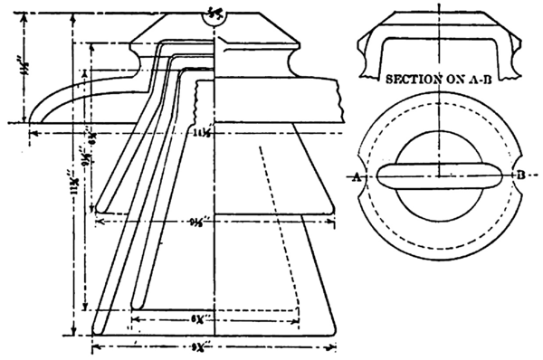 |
| Figure 9. Sixty-Thousand-Volt, Fourteen-Inch Porcelain Insulator. |
As the time will probably come when 100,000 volts will be as common as 10,000 is today, we have not yet reached the limit of development in line insulation. In testing the insulators, each part is subjected to more than the normal voltage from line to ground. The top is generally tested to 55,000 volts, the center to 45,000 and the middle petticoats to 40,000 volts. The test is made with salt water as electrodes.
2. PinsWe are using iron pins on all our new work, and believe the idea of depending on the pin for insulation is wrong. Place the strain where it belongson the insulators, each part is subjected to more than the normal voltage from line to ground. The top is generally tested to 55,000 volts, the center to 45,000 and the middle petticoats to 40,000 volts. The test is made with salt water as electrodes.
2. PinsWe are using iron pins on all our new work, and believe the idea of depending on the pin for insulation is wrong. Place the strain where it belongson the insulator. We are making our pins of pipe drawn down at one end. The pins are galvanized and a lead thread then cast to fit the insulator.
3. General Line ConstructionWe are constructing our 60,000-volt lines with a six-foot spread, the wires being on the corners of a triangle. On our late work we are using tall poles and spreading about double the distance ordinarily used. In the mountains, where we can take advantage of the hills and ravines, we use long spans, having some aluminum spans of 1000 to 1800 feet in length.
A tower construction using a span of about 500 feet would make an ideal line, and a line not much more ex pensive and much easier to care for than the ordinary pole line.
Our method of entering buildings is through a piece of plate glass about twenty-four inches square, having a hole about three inches in diameter through which the wire passes. The glass is held by a simple wood frame. This construction is more satisfactory than the old method of passing through terra cotta pipe.
4. Line OperationThe lines are operated by keeping men at important points who patrol the lines from one to three times a week, depending on the condition of the line, these men being ready at all times to go out in case of emergency.
Our line troubles have been due to a few weak insulators; in some localities we have a good many insulators shot off. Some of our unexpected causes of trouble have been cranes or geese flying into the line; cats climbing up on the poles; green hay carried by wind dropped on the line; an engine starting up under the lines; a long-tailed rat crossing temporary busbars.
5. TransformersOur transformers have given us very little trouble and are really the most satisfactory part of the system. High primary insulation and care in the handling of the oil to keep it free from dirt and moisture are of prime importance. The windings should be dried out before adding the oil.
 |
| Figure 10. Sixty-Thousand -Volt, Four-Break, Oil Switch. |
That the presence of the oil does not add to the fire risk was amply demonstrated by a fire at the Colgate station in March. 1903. The transformers were in the hottest part of the fire and were damaged but little, the oil acting as a protection to the winding. The transformers were not responsible for the fire, as was reported at the time.
On test, the primary of each transformer should stand a test about equal to double the star voltage for which the transformer is designed. That is, a transformer which is to be connected 30,000 star, giving 51,960 volts line pressure, should stand an insulation test of about 100,000. Some manufacturers put on a test voltage from two to three times the transformer voltage. Less than two and one-half is not a good test.
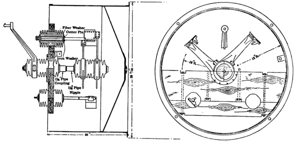
6. Switches We find it convenient to use two types of switches to handle the electrical energythe oil type and the air type. That the oil type switch is the only one that will stand heavy duty has been amply demonstrated. As it has not been possible to purchase satisfactory switches in the market, I have designed a line of switches for our high potential work.
 |
| Figure 11. Sixty-Thousand-Volt Oil Switch in Place. |
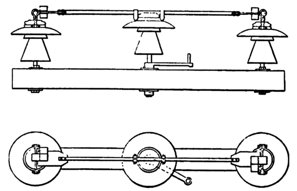
We are now using the switches shown in Figure 10 at our power houses, designed to handle from 10,000 to 40,000 kilowatts at 50,000 or 60,000 volts. Each pole is in a separate tank and mounted in a fireproof compartment, as shown in Figure 11. The three poles are operated together. The switch, as shown, gives four breaks per leg.
 |
| Figure 12. Sixty-Thousand-Volt Two-Break Oil Switch. |
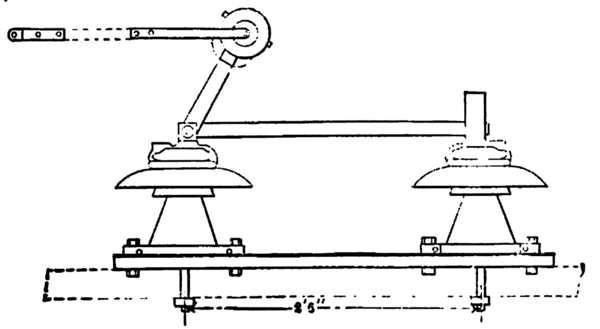
On less important work we use the two-break switch shown in Figure 12. This is a very simple and inexpensive design, but answers all purposes as well as more elaborate switches. Switches having the same operating principle, but mounted designed differently, designed by R. H. Sterling, have been in service on the system for several years and have given very good results. This switch will open 10,000 kilowatts at 60,000 volts on short circuit.
Disconnecting switches are used on each side of the oil switches, as shown in Figure 11, that the switch may be examined and repaired with line and busbars in service.
 |
| Figure 13. Sixty-Thousand-Volt Disconnecting Switch. |
 |
| Figure 14. Sixty-Thousand-Volt Disconnecting Switch. |
For connecting transformers to busbars we use three-pole disconnecting switch, as shown in Figure 13. This is a simple design and works perfectly. Figure 14 gives a large view of the switch. As shown by Figures 11 and 13, each busbar is run in a separate duct.
 |
| Figure 15. Sixty-Thousand-Volt Outdoor Line Switch. |
For an outdoor switch for substations and branch lines where the load does not exceed about 1000 kilowatts, we use the switch shown in Figure 15. The switch is mounted so that the three poles open simultaneously from a distant point. Electrically all switches on the system are liable to have the same duty to perform in case of a short circuit beyond the switch, and some make it a practice to have all switches the same, depending upon the power behind them. While this is correct electrically, the liability of trouble is slight and it is better to assume that you will occasionally burn up an inexpensive switch by trying to open on a short than it is to burn up all your money in the beginning by installing every switch of a high capacity, and at great expense.
7. Lightning ArrestersFor lightning protection we have decided to pin our faith to the horn arresters, these made with single or double air gap. This simple device with good transformer and line insulation has given good results. Lightning is very often blamed for troubles that are primarily due to insufficient insulation and ignorance.
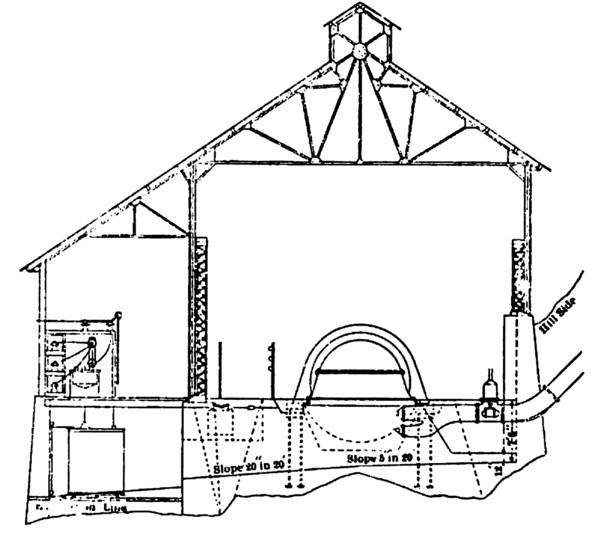 |
| Figure 16. Showing General Arrangement of Power House. |
8. General Arrangement of Power HouseFigure 16 shows my idea of the general arrangements of a power house in the mountains. Our high head power stations are usually in deep canyons, and the logical method of construction, it seems to me, is to take advantage of the natural slope, as shown. We go from the generator through the 2300-volt switch located under the floor, then to the transformers, which are located on a lower level than the power house, with the floor left open so the operator can see the transformers and note the temperature on the dial. The floor level of the transformer room may be below the high water line. From the transformers we come up to the disconnecting switches, then through the oil switches to a second disconnecting switch to line. Locating the transformers in this way puts them in view of the operator, the practice of constructing a separate transformer room at a distance being wrong, in my opinion.
For fire-walls we have the tail races between banks. I have yet to see a transformer in trouble that could not be pulled off before anything more than an injury to the coils had resulted. The switches being located in fireproof rooms makes it impossible for fire to spread in any way. The arrangement given, it is believed, has a great many advantages, being compact, safe, easily operated and economical.
Our general practice is to generate at 2300 volts and step up to the line voltage, the primary of transformers being connected star with grounded neutral. I have come to believe the grounding of the neutral to have more advantages than disadvantages. We take advantage of the grounded neutral and very often install a single transformer in a substation, one side going to line, the other to ground; where the load is larger but does not warrant three transformers we put in two using two legs of the primary and open delta on the secondary. We are not bothered by any unbalancing of load at the power houses.
At the power houses we use no fuses or circuit breakers, preferring to hang on to a short rather than take chances of pulling the line off for every slight interruption. At substations the transformers are generally fused.
The size of our units has gradually increased from 300 kilowatts, installed in 1897, to our present 5000-kilowatt units. The 5000-kilowatt unit is of the two-bearing type with overhanging water wheel. With this type we can put 20,000 kilowatts in a building 100 feet long by fifty feet.
9. Line VoltageRegarding the proper voltage to be used for transmission, this will depend on conditions, mainly on the length of line. From fifty miles up it will be generally economical to use as high a line voltage as is practicable. At the present time 60,000 volts can be safely handled, and 80,000 volts is not out of reach in certain localities by those experienced; and judging the future by the past, we may expect to reach 100,000 operating voltage in a few years.
Our greatest trouble is occasioned by the fog. This in districts near the ocean or bay settles on the insulators and reduces the insulation to such an extent that the pins, cross-arms or poles, if of wood, are set on fire. In the mountain districts with modern insulators our line troubles are practically nil. Those without experience in the fog districts cannot realize the difficulties of insulating against a heavy fog. The weak point of the transmission system is the insulator. With an insulator to stand 100,000 this voltage is possible.
To sum up, experience shows that it is easiest to operate a line at 50,000 or 60,000 than at 25,000 or 30,000, assuming that a considerable amount of power is transmitted.
(1) A paper presented before the International Electrical Congress, St. Louis, Mo., September 12-17, 1904,
