[Trade Journal]
Publication: The Journal of Electricity, Power and Gas
San Francisco, CA, United States
vol. 14, no. 10, p. 403-417, col. 1-2
The Puyallup River Water Power Development
THE cities of Seattle and Tacoma, Washington, and their suburban towns, have in five years increased in population from 130,000 to upwards of 225,000; the growth of manufacturing industries and construction of street and interurban electric railways has kept pace with the increase of population, and to supply the consequent demand for electric power an unusually large generating plant of the most modern type has been constructed on the Puyallup River.
| |||
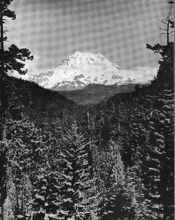
| Mount Rainer From the Flume Line Near Automatic Spillway. |
The Puget Sound Power Company, the owner of the plant, was organized in the year 1902 for the purpose of developing water power for use by the Stone & Webster properties in Seattle and Tacoma. Before beginning the construction of the plant a careful investigation was made of the variations in the flow of the several rivers in western Washington and the other features which would affect the reliability of the service obtainable from each, and a general plan was then adopted for the development of this power on the Puyallup River with an initial installation of 20,000 horsepower, the plans being made and the greater portion of the work carried out on the basis of continuing the initial installation to an ultimate development of 40,000 horsepower.
The design consists of diverting the Puyallup River just below the junction with the Mowich and carrying the same by means of a flume ten miles to a reservoir located on a high plateau, and thence discharging by means of steel pipes against wheels in the power house under a head of 872 feet, the water wheels so driven to be direct connected to electric generators, and the electric power so produced to be transmitted at a pressure of 55,000 volts forty-eight miles to Seattle and thirty-two miles to Tacoma. All water rights and the necessary land abutting on the river from the point of diversion to point of return were secured; also all land necessary for flume and other structures, and actual work of development was commenced March 1, 1903. To facilitate construction a spur track two and one-half miles long was built from the Kapowsin station of the Tacoma Eastern Railroad to a new station at Electron, and continued a mile further to the power house site. From Electron a standard gage cable incline was built to lift to an elevation of about 950 feet to the reservoir site above the power house, and a wagon road to the head works. The first generator unit of 5000 horsepower was put into commercial operation delivering power to Seattle and Tacoma on April 14, 1904 less than fourteen months after work was commenced; the plant was put into complete operation for its initial installation of 20,000 horsepower on July 23, 1903.
| |||
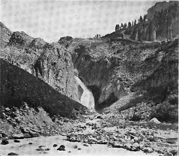
| Mowich Falls on the Head Waters of the Puyallup River. |
| |||
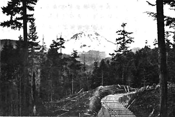
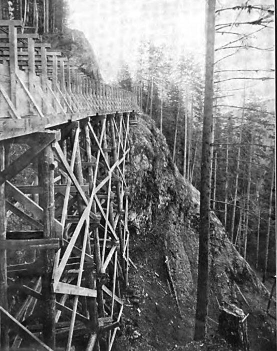
| Partially Constructed Flume Line Showing Mount Rainier in the Distance. |
The Puyallup River has its source in the glaciers of Mt. Rainier, next to the highest mountain in the United States and one of the great peaks of the world, covering 200 square miles and rising 14,500 feet above the waters of Puget Sound. That part of the mountain higher than 5000 feet above sea level is covered with snow and ice, and the precipitation resulting from the moisture laden air of the Puget Sound region coming in contact with the glacial cold of the mountain sides is estimated to average 140 inches per annum. The fields of ice and snow which result from this precipitation are constantly moving down the mountain sides to the valleys about its base in the form of slowly moving glaciers of many square miles in extent, which fill the valleys to the depth of hundreds of feet, and are constantly being added to from above and melting away below.
| |||
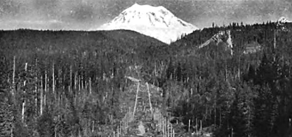
| View of the Transmission Lines, Cable Incline, Reservoir, Penstock and Mount Rainier, Looking East. |
These great masses of ice increase in size and depth each winter and decrease by melting under the heat of summer, and the hottest and driest days of summer produce the greatest rate of melting. The Puyallup and Mowich rivers drain a fan-shaped section of the mountain and five of the glaciers described, and thence flow through mountain ranges which add greatly to their volume, each for a distance of about twelve miles from the glaciers, and then join together, the combined river being then known as the Puyallup. The watershed of these rivers includes a rough and heavily timbered country not covered with ice or snow and below the very high mountain range. The streams of this lower timbered country are fed by the copious rains of the Puget Sound country which occur during the fall, winter and spring months concurrently with cool weather. During such cool weather the rain and the run-off in this timbered section is heavy and at the same time snow and ice accumulate on the mountain and the run-off from it is comparatively small. When the warm weather comes the rain and the run-off from the timbered section is at a minimum and the melting of the snow and ice on the mountain and the run-off from the same is at a maximum. This balance, or alternation of the heavy run-off from the timbered and ice sections, results in a remarkably uniform flow in the river at the point from which the water is taken for power purposes, and makes the operating conditions in using this stream ideal.
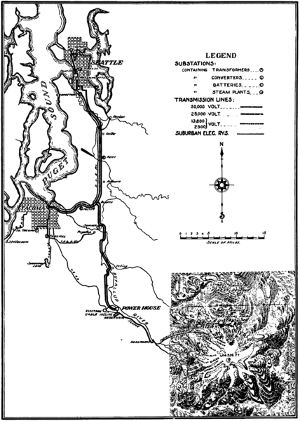 |
| Map of the Puyallup River Development of the Pudget Sound Power Company, Showing Also Auxillary Transmission Lines and Substations of the Pudget Sound Electric Railway, Seattle Electric Co. and Tacoma Railway and Power Co. |
Although the dam and intake are located within ten miles of the nearest glacier, the elevation at this point of diversion is only about 1700 feet above sea level, and the climate at this elevation is so uniformly mild and the water flows so rapidly that no ice comes down the river nor is formed either in the flume or reservoir.
The power is used for all branches of servicelight, power and railway. It supplies the electric railway systems in Seattle and Tacoma aggregating 168 miles of trolley road, the multiple unit, third rail line between Seattle and Tacoma, two cable roads, one in Seattle and one in Tacoma, furnishes power for numerous factories, together with the shops of the Northern Pacific Railway and the new pumping plant of the city of Tacoma, and supplies the greater portion of commercial and residence lighting and street lighting in Seattle and in the towns between Seattle and Tacoma.
Much of the power is distributed as alternating current two-phase for power and single-phase for lightingbut there is also connected 10,000 kilowatts of converting capacity for producing direct current, 2000 kilowatts of which is used for light and stationary motor supply. The bulk of the converting machinery (7300 kilowatts) being of the synchronous type, it is not necessary for the water power plant to generate or transmit idle currents.
| |||
| Flume Line Through the Rock Canyon of the Puyallup River. |
| |||
| Intake and Dam, Looking East, Showing the Uncompleted Radial Gate at the Left. |
The distribution of the current to the various localities and the transformation and conversion for various uses takes place at eleven substations containing 26,000 kilowatts of transformer capacity. Six of these are designed for transforming the 55,000-volt current to lower voltage and eight contain machinery converting to direct current for railway use. Ata point one-half mile below the confluence of the Puyallup and Mowich rivers, and about 1700 feet above sea level, is located the dam and intake of the Puget Sound Power Company. Here the water necessary for the operation of its plant is diverted by a low, solidly constructed dam, through a masonry intake to a flume which is constructed on the southwest side of the river for a distance of ten miles. The dam or diverting weir is 200 feet long and five feet high, and covers the bed of the river longitudinally for a distance of sixty feet exclusive of the down stream apron. It is built down to an impervious bottom of clay hardpan, and is made tight by three rows of triple lap sheet piling set into hardpan bottom and bedded in concrete; it is faced with 6x12 timber covered at the crest with one-quarter-inch boiler plates, and besides the whole dam being a spillway, there is a lower spillway thirty feet wide to localize scour at the intake end. The intake is set at right angles to the dam and is constructed of concrete masonry. It is sixty-two feet wide at the river bank, and is protected by a screen grating made of iron bars one-quarter-inch by four inches by six feet, spaced two and one-half inches. Provision is also made for the insertion of flash boards in grooves in steel frames in such manner as to regulate or entirely shut off the intake at a point between the river and the grating. A radial gate of unique design is also installed at the junction of the masonry intake and the flume for the purpose of quickly controlling the amount of water delivered to the flume.
| |||
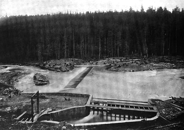
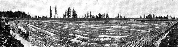
| Interior of the Reservoir During Construction , Showing the Arrangement by Which the Plant Was Operated Without Filling the Reservoir. |
| |||
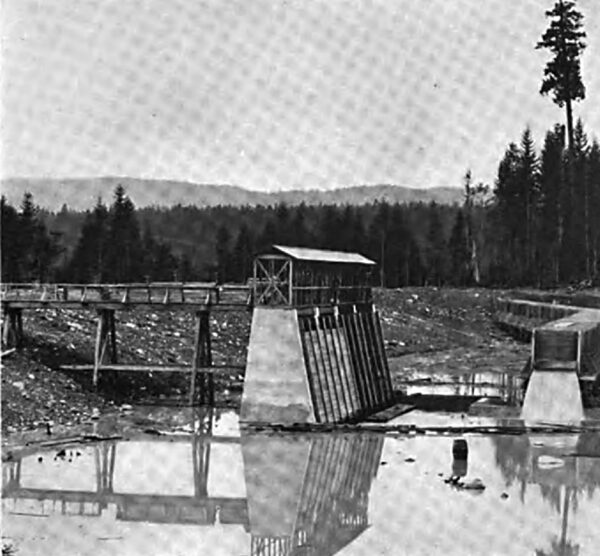
| Automatio Regulating Spillway at the Entrance to the Reservoir , Showing the Back Water Overflow and Waterway. |
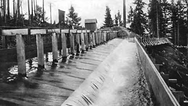
From head works to reservoir, a distance of about ten miles, the water is carried in a flume which as now constructed is eight feet wide and five feet high inside measurements, but is framed for the addition of plank to make it eight feet high. The flume is supported on low trestle work which follows the contour of the land. This trestle work is the same construction and of equal strength to that usually used for railroads, and in fact during the construction heavy work trains were operated over its entire length. The flume proper is constructed of surfaced planks two and one-quarter inches in thickness and twelve inches wide, and the frames which surround it are spaced with four feet centers, built on a uniform grade of seven and one-half feet to the mile. Sand boxes and automatic spillways are provided at various points along the flume, and a number of gates are also provided for emergency use, while a light railroad track for handcars of standard gage is laid along the top of the flume to facilitate inspection and repairs.
All danger timber along the line of the flume is being removed, and the flume trestle is built on rock or hardpan foundation which protects it against trouble from slides. In constructing this flume the usual plan of building curves as a series of tangents was not followed, the bends in the flume being made with true curves presenting a uniform and smooth interior surface and thus facilitating the flow of water.
| |||
| Panoramic View of the Reservoir and Forebay Pool, Showing the Simultaneous Operation and Construction. |
| |||
| A Panoramic View of the Water Inlet, Forebay and Partially Filled Reservoir. |

The flume discharges its water into a reservoir located on a high plateau, nearly 900 feet above the power house. This reservoir serves as a relay to maintain the plant in continuous operation, in case of interruption of water supply, and also serves the very useful purpose of supplying water for temporary overloads in excess of the discharge capacity of the flume, or, in other words, for equalizing the daily fluctuations of load. The location of the reservoir is particularly well adapted for the purpose, the material excavated from the higher side of the site was used to form the embankment on the lower side of the reservoir. This material is a glacial boulder soil of clayey consistency which required blasting before it could be handled with a steam shovel. It puddled well and formed a water tight fill which set hard in the embankment almost like concrete.
The flume enters one end of the reservoir, and, when the latter is drained, as shown in the illustration, discharges into a concrete basin in front of the forebay. This arrangement permits the emptying of the reservoir for inspection or cleaning without interrupting the delivery of water to the power house, and distributes the water quietly to the penstocks without danger of carrying air into the pipes.
| |||
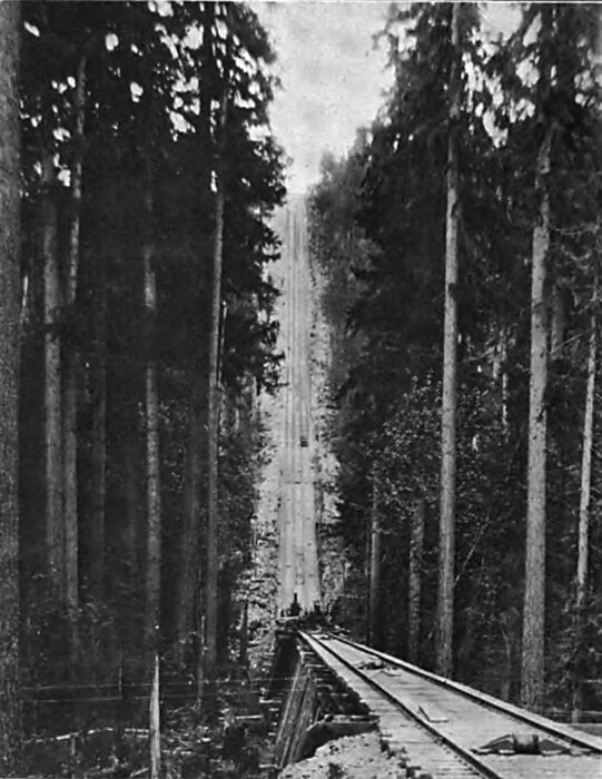
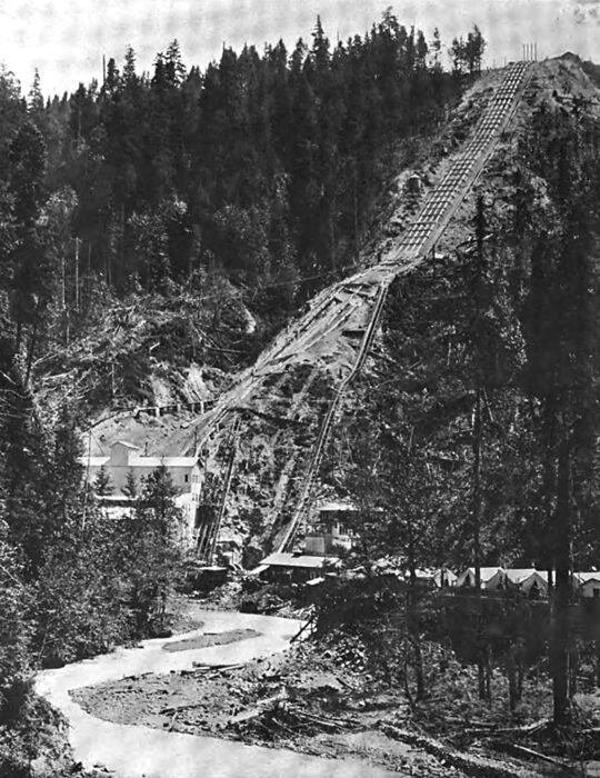
| Incline Cable Railway for Hoisting Building Material Up the 68 Per Cent. Grade From Electron to the Reservoir. |
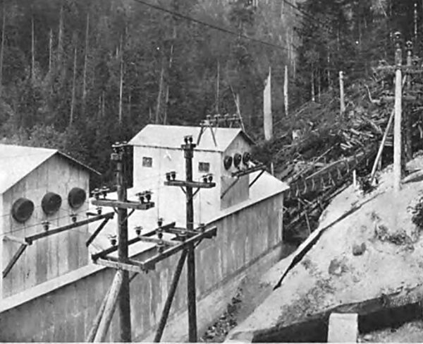
| |||
| Camp 2, Showing the Superintendent's Cottage, the Power House and Penstock Lines Looking South. |
The forebay is of concrete and is constructed inside of the reservoir and is divided into compartments forming separate gate chambers for the main penstocks. Each compartment is provided with iron racks or screens with stop boards to permit inspection or repairs without emptying the reservoir. The gates are arranged for connecting an electric motor drive to be controlled from the power house. The depth of water in the reservoir is at all times shown at the power house switchboard by a Dibble automatic electrical indicating and recording water gage fitted with low water alarm. This gage is operated by three wires running from a float-actuated Dibble transmitter located in the reservoir.
The penstocks, one for the two exciters, one for each of the four generating units now installed and one for each of the remaining four units to be installed later, are carried through the reservoir embankment in the form of concrete protected wood stave pipes, joining the steel pipes just outside the reservoir embankment. Of the eight main pipes for the complete plant, four, together with the exciter pipe, are now continued about 1700 feet down an incline of about thirty degrees to the power house on the river bank below. Each main pipe is of riveted steel forty-eight inches in diameter and one-quarter-inch thick at the upper end, tapering to thirty-six inches in diameter and three-quarter-inch thick at the lower end, and was furnished by the Risdon Iron and Locomotive Works. The penstocks are anchored by massive concrete abutments, and all surface water is carefully drained away, and as a further security the pipes are protected with back filling of earth on which is planted quick growing vegetation.
| |||
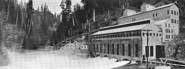
| West Side of the Power House. Showing Four Generators in Operaton: Also the Temporary Wall and Grading and Trenching to the Right to Facilitate the Installation of the Four Additional Penstocks and Generators. |
| |||
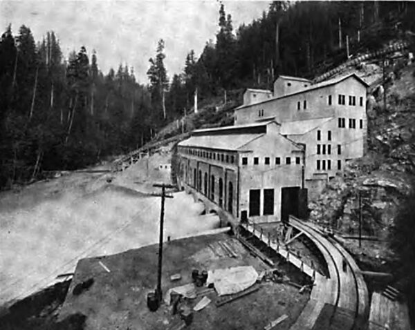
| End View of the Power House Showing Four Generators in Operation. This View Shows the Temporary End Wall and the Trenching and Grading in Progress at the Right to Facilitate the Install Ation of the Four Additional Units. |
| |||
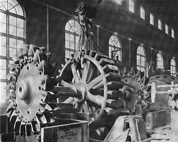
| Placing the Water Wheels and Rotor Shaft of A Single Unit in Its Bearings. |
The power house is built in the bank of the river on a foundation of piling and rock; it is of massive concrete, brick and steel construction; the building for eight units will be about one hundred by two hundred and sixty-six feet, divided longitudinally into two parts, a generator house and a transformer and switching house. The generating units are arranged parallel to and along the river side of the building, the penstocks being brought to them under the main floor from the rear. The transformers are grouped in isolated rooms of concrete in the basement of the switch house; the switching apparatus and wiring being in compartments overhead as hereafter described.
Each unit consists of two overhung Pelton water wheels, ten feet six inches in diameter, mounted on each end of the shaft of each 5000 horsepower two-bearing generator; the nozzles are of the needle type arranged for automatic deflection by Lombard type L governors for speed control, the operation of the needles being only for economic adjustment of the discharge to the load of the machine; each nozzle is also provided with a motor-operated gate valve for cutting off the water supply. The wheels have a maximum capacity of 7500 horse-power for each unit.
The wheels are arranged to be started and stopped and adjusted for speed from the main operating switchboard at one end of the generator room; motor-driven pumps provide oil supply for ordinary lubrication, pressure oil for forced lubrication in starting, and circulating water for cooling bearings.
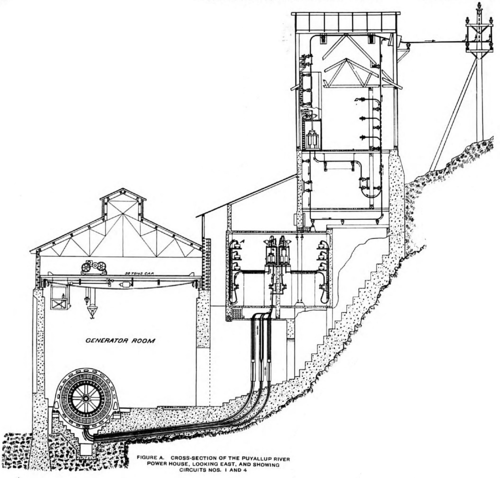 |
| Figure A. Cross-Section of the Puyallup Water Power House. Looking East, and Showing Circuits 1 and 4. |
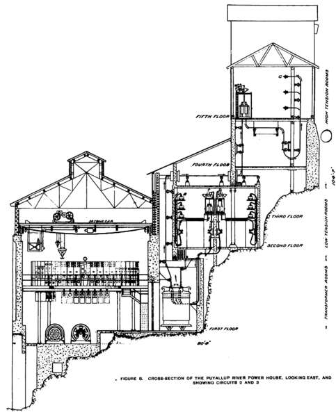 |
| Figure B. Cross-Section of the Puyallup Water Power House. Looking East, and Showing Circuits 2 and 3. |
The rotors and wheels are hydraulically forced onto a twenty-four-inch hollow nickel steel fluid compressed shaft. The spray from the wheel discharges collecting in the water wheel housing enters this hollow shaft and automatically serves to cool the bearings. At the date of their installation these were the largest impulse wheel units in the world.
There are four General Electric Company make revolving field generators of 3500 kilowatts capacity each, with an overload capacity of 25 per cent. for two hours, wound for three-phase current at 2300 volts and a frequency of sixty cycles per second.
Two 150-kilowatt, 125-volt, 600 revolutions per minute, shunt wound exciters are provided, each direct connected to an overhung Pelton water wheel and to a 2080-volt, 200 horsepower, three-phase induction motor. The wheels driving exciters are not provided with automatic governors, the direct connected induction motors serving this purpose, and operate either as motors or generators according as they run below or above synchronous speed. The motors also afford a relay source of power for excitation in case of failure of an exciter water wheel or its water supply. Each exciter is capable of exciting six generators under all conditions.
| |||
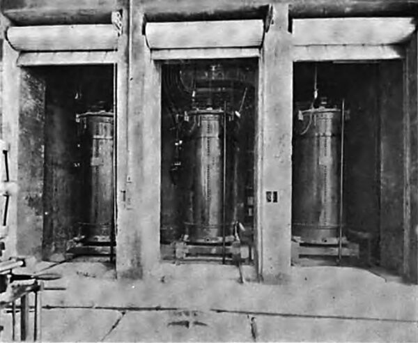
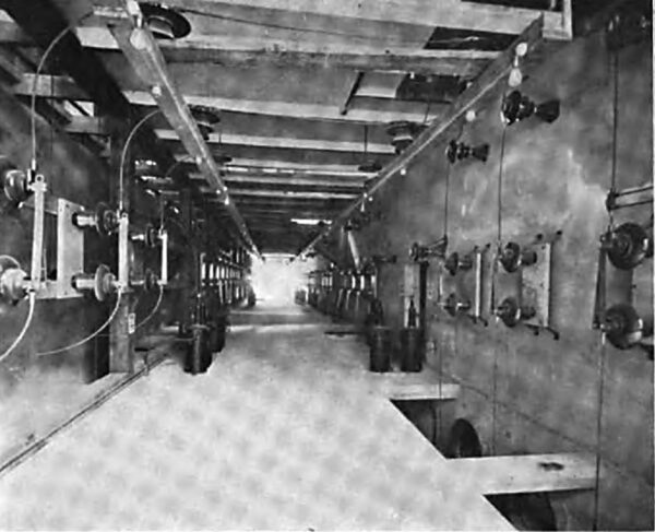
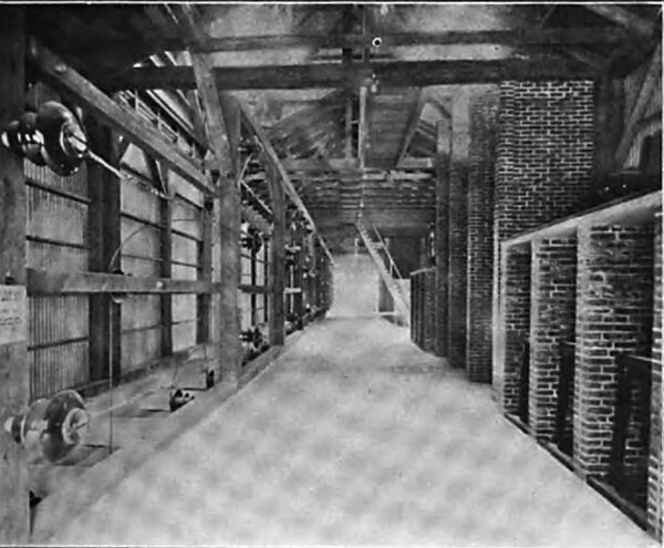
| View From the Generator Room, Showing One of the Three Groups of Step-Up Transformers, Each Group Consisting of Three 2300 - Kilowatt 2300 55,000 -Volt Transformers. Each Group of Three Transformers is Placed in A Concrete Cell With Concrete and Brick Vent Through Roof, the Entrance to the Cells Being Protected With Iron Roller Doors. |
| |||
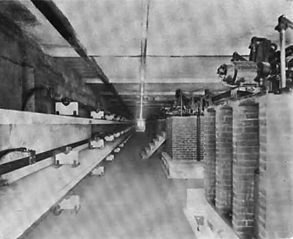
| Longitudinal View of the North Side of the Third Floor of the Concrete Switch House, Showing to the Left One Set of 2300 - Volt Busbars and With Concrete Barriers, and to the Right the Remote Control Generator and Transformer 2300- Volt Oil Switches. This Entire Arrangement is Duplicated on the South Side of This Floor. |
| |||
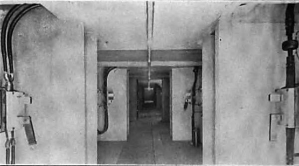
| Longitudinal View of the North Side of the Second Floor of the Concrete Switch House, Showing the 2300- Volt Disconnecting Switches Placed Below Oil Switch Room. Note the Barriers Between Disconnecting Switches. |
| |||
| Longitudinal View on the Fourth Floor of the Concrete Switch House and Showing the Current Transformers for Instruments and the High Tension Disconnecting Switches for Isolating the Oil Switches on the Floor Above. |
There are three banks of transformers installed at the power station, each bank consisting of three 2333-kilowatt, water cooled, oil insulated, General Electric Company transformers, with 25 per cent. overload capacity for two hours. Each bank has a capacity equivalent to two generators, the third bank being spare, so that the failure of even a complete bank would not diminish the capacity of the station. The transformers are connected delta on both the high and low tension sides, and the arrangement of the windings is such that with 2300 volts on the low tension side, high tension voltages of 27,500, 45,000 and 55,000 may be derived. These transformers have been operated at 55,000 volts from the beginning.
Water for cooling is derived from a spring above the power house, supplemented by connection with the reservoir. The transformers are piped so that the oil can be removed from the cases into large storage tanks, and an emergency blow-off valve is arranged to discharge the oil quickly into the river.
Before filling these transformers with oil they were dried out at a temperature of 80 degrees Centigrade under a vacuum of twenty-six inches for ten hours. No oil was used that did not stand a potential test of 40,000 volts between one-half-inch flat electrodes placed two-tenths of an inch apart. After filling and allowing the oil to thoroughly settle, samples of oil from the bottom and top of each transformer were subjected to the above potential test, and no transformer was put into service before the oil passed this test satisfactorily.
For connecting each generator and transformer bank to the low tension busbars, and each transformer bank and transmission line to the high tension busbars, a full complement of remote control, motor-operated oil switches is provided.
There are two sets of 2300-volt busbars, designated as the main and auxiliary busses. The main bus is for regular operation, while the auxiliary bus is for emergency operation and for relaying the main bus in case of repairs to the latter. Both sets of busbars are identical, and any transformer bank can be connected to either set.
| |||
| Longitudinal View of the Fifth Floor of the Switch House, Showing High Tension Sectional Bus to Left, and Lightning Arresters and High Tension Transformer and Transmission Line Switch Cells to Right. |
Between each generator and each set of 2300-volt busbars there are two sets of disconnecting switches and a triple pole General Electric Companys type H, 1200-ampere, motor-operated oil switch, a set of disconnecting switches being on either side of the oil switch. Between each set of burbars and each transformer bank there are two sets of disconnecting switches and a type H, 3000-ampere, motor-operated oil switch, the arrangement being similar to that of the generator switches. The purpose of the disconnecting switches is to remove the potential from the oil switches that inspection of or repair to the oil switches may be safely made. The disconnecting switches are not to be operated when carrying current except under emergency conditions. All ordinary switching is done by means of the oil switches, which simultaneously open and close the three legs of the three-phase circuit. In addition to the single pole, double throw switches mounted on the operating panels for opening and closing these switches, when cutting in or out a generator or transformer bank, there is for each oil switch a clock-type time limit relay actuated by secondary current from current transformers in circuit with that switch, these relays operating the motor connected to the oil switch in case of an overload or short circuit lasting the period for which the relay is set. These relays can be set for overload periods of four seconds down to a small fraction of one second, it thus being possible to automatically localize short circuits on the system, and in apparatus, without completely shutting down the system. The electrical arrangement of the motors driving the exciters is the same as that of the generators.
There is one set of high tension busbars, divided into three sections by sectionalizing switches, each transformer bank being connected to a corresponding section, and one line to each of the end sections.
Between the high tension bus and each bank of transformers there are two sets of disconnecting switches and one triple pole, General Electric Company, 60,000-volt, 400-ampere, motor-operated oil switch, a set of disconnecting switches being on either side of the oil switch. There are two outgoing high tension lines, and each line is controlled, as just described, for the transformer banks. All the high tension oil switches possess automatic features as described for the low tension oil switches.
Lightning arresters without reactance coils are provided for each outgoing line.
Static dischargers are provided for the low tension side of each transformer bank. These static dischargers consist of three 2500-volt single pole lighting arresters connected in star, the neutral point grounded. They limit the potential of the low tension winding to 2500 volts above ground, and would come into action in case of grounding of one side of the transmission line or transformers.
The control of all the oil switches 1s from operating panels erected on a gallery in the east end of the generator room, at an elevation of fourteen feet above the generator room floor. The arrangement of panels from left to right is exciter panels (generator end), exciter panels (motor end), generator totaling panel generator panels, transformer control panels, and high tension line panels.
The generator and exciter field rheostats are hung below the gallery and are operated from pedestals by means of shafting and bevel gearing, the contact plates being on the rheostat boxes. The highest alternating current potential on the switchboard panels is 115 volts, derived from potential transformers, and the highest direct current potential is 125 volts, derived from the exciters. Each generator panel contains three ammeters, one voltmeter, a polyphase indicating wattmeter, a polyphase integrating wattmeter, and a field ammeter.
Each outgoing line panel contains three ammeters, and the totaling panel contains a power factor indicator, a frequency indicator, a curve-drawing voltmeter and three curve-drawing ammeters. The curve-drawing instruments belong to a type lately developed by the General Electric Company, giving a record three inches long per hour.
The control of the plant is completely from the switchboard gallery, a water wheel may be started or stopped, a generator brought up to voltage, synchronized with other generators on either bus, a transformer bank cut in on either bus and a transmission line connected in circuit without the presence of a person in the room where the actual switching is done, the lighting of a red lamp indicating the closing of a switch and a green lamp the opening of a switch.
Figures A and B show sections through the generator room and switch house. The transformer rooms are at the same level as the generator room, but isolated from the latter by rolling steel doors. On floor No. 2 are the low tension disconnecting switches, the generator and transformer cables going to the sets of disconnecting switches on either side of the middle partition; the disconnecting switches installed between the oil switches and the bus being on the outer walls and immediately below the busbar compartments, which are above on floor No. 3. In the center of floor No. 3 are the low tension oil switches, the two oil switches corresponding to a generator or transformer bank being arranged back to back and facing their corresponding set of busbars. The busbars are of the laminated type, consisting of flat copper bars with expansion joints and supported on marble slabs set on edge which in turn rest on concrete slabs forming barriers between adjacent busbars. The compartments formed by the concrete slabs are to be covered by insulating fireproof doors.
The oil switches are installed in brick cells with soapstone bottom and top slabs and doors. Each pole of a switch is separated from the other poles by brick barriers.
The same general scheme is used for both the low and high tension disconnecting switches and oil switches, except that only one set of high tension busbars is at present installed, provision being made for the later installation of the second set. The high tension disconnecting switches and current transformers are on floor No. 5, while the high tension oil switches are on floor No. 6. Above floor No. 6 are the two outgoing high tension line towers, in the north end of which are the high tension lightning arresters, each pole being separated from its adjacent pole by brick barriers extending the full length of the arrester. The lines emerge from the wire tower centrally through an extra heavy thirty-inch sewer tile covered by a glass plate.
From the power house two parallel transmission lines run a distance of twenty-two miles to Bluffs, a station on the line of the Puget Sound Electric Railway, nine miles from Tacoma and twenty-five miles from Seattle. From Bluffs one line runs for a great part parallel to the transmission line of the Puget Sound Electric Railway to Seattle and one to Tacoma; also parallel to the transmission line of the Puget Sound Electric Railway.
| |||
| Wire Towers, Showing the High Tension Transmission Line As It Leaves the Power House. |
| |||
| 1. A Standard Curve Construction on the Transmission Line. :: 2. A Right Angle Turn in the Double Line at Orting. :: 3. the Junction of the Seattle and Tacoma Lines at Bluffs, Showing the Disconnecting Switches. :: 4. Where the Transmission Lines Cross the Northern Pacific Railway at the Meadow. |
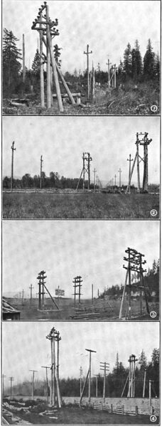
The transmission line of the Puget Sound Electric Railway is at present operating at 27,000 volts, but the line is designed for operation at double this voltage, so that when this line is changed over to a 55,000-volt basis there will be two complete and independent pole lines from the power house to Seattle and Tacoma. At Bluffs there are erected junction pole switches by which the two transmission lines may be cut through independently, one to Seattle and one to Tacoma, or both lines put in multiple, or any section isolated without interfering with the operation of the other sections.
From the power house to Bluffs a private right of way has been secured, the two pole lines being from fifty to eighty feet apart. When passing through wooded sections all dangerous timber has been cleared well back on the land adjacent to the right of way on both sides, so as to completely protect the transmission line.
The minimum length of poles used was forty-five feet, with a minimum top diameter of ten and one-half inches. The standard spacing is 125 feet on straight line and 90 to 100 feet on curves.
The main cross-arm is five-inch by seven-inch by seven-foot four-inch Washington fir, boiled in raw linseed oil, giving it a much longer life than an untreated arm. This arm is bolted to the pole by two galvanized iron bolts and braced by a combination wood and galvanized iron brace. At the top of the pole is a five-inch by seven-inch by eighteen-inch arm supported by an angle iron frame bolted to the pole by two galvanized iron bolts. The main arm supports two insulators and the top arm one insulator, giving an equilateral triangular spacing of seventy-two inches between wires.
The pins on one line from the power house to Bluffs and from Bluffs to Seattle and Tacoma are galvanized malleable iron, cast hollow and circular in cross-section and having a shank diameter of two and one-half inches. The pins on the other line are of the same general exterior form and dimensions, but turned from eucalyptus wood and treated with linseed oil. The iron pins and eucalyptus pins are entirely interchangeable in all parts of the construction.
The insulators are of dark brown glazed porcelain, a small portion being furnished by the Locke Insulator Manufacturing Company and the greater portion by R. Thomas & Sons. The insulators are a special design adopted after tests on a number of samples of varying design. The insulator consists of a broad umbrella-shaped top fourteen inches in diameter and three inner shells cemented together and to the iron pins by neat Portland cement. They weigh twenty-two pounds and stand a potential of 90,000 to 100,000 volts before arcing over under an artificial rain test. The separate parts of the insulators were given a dry potential test at the factory before shipment, and after assembly at Tacoma and before shipping out on the line they were again tested to a potential corresponding to the dry arcing-over voltage. So far the behavior of these insulators under the weather conditions that have existed since the plant was put into operation, and under a line voltage of 55,000 volts, has been entirely satisfactory.
The line wire on both lines from the power house to Bluffs and from Bluffs to Seattle is nineteen strand 4/0 semi-hard drawn copper cable, and from Bluffs to Tacoma is solid 1/0 semi-hard drawn copper wire. The wires are transposed, making a third of a turn about every four miles. The telephone line is supported on cross-arms seven feet below the main arm, and consist of two No. 10 hard drawn copper wires, transposed every tenth pole, the glass insulators being double petticoat, deep groove, on locust pins. The operation of the telephone line with the above construction has been entirely satisfactory. The company also has an independent telephone line leased from the Sunset Telephone and Telegraph Company and constructed over another route.
Eighteen miles from the power house and along the transmission line from the power house to Bluffs is the town of Sumner. In Sumner has been built a substation to accommodate two 100-kilowatt, 50,000 to 2300-volt transformers for local power and lighting. At present only one transformer has been installed, furnishing current for lighting Sumner. A 2300-volt line will be built from Sumner to Puyallup, a distance of three miles, for supplying the city of Puyallup with current for lighting and power, taking the place of the steam plant at present in operation.
The receiving station in Seattle is built on Massachusetts Street, near the southerly city limits. Here the high tension current is stepped down to 2300 volts for local distribution to the stations of the Seattle Electric Company.
| |||
| The Massachusetts Street Substation, Seattle, Showing the High Tension Wiring and Disconnecting Switches. |
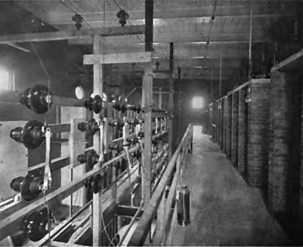
Control is provided for the two incoming high tension lines by means of high tension motor-operated oil switches, and for two 4000-kilowatt banks of transformers and for three outgoing 2300-volt feeders. The control of the transformers consists of a motor-operated, 60,000-volt, 400-ampere oil switch on the high tension side of each bank of transformers, and a motor-operated, 2500-volt, four pole oil switch on the low tension side of each bank. The control of the 2300-volt outgoing feeders is by motor-operated, four pole oil switches similar to the transformer low tension switches, differing only in capacity, the former being 800 amperes and the latter 1200 amperes capacity. Allot the oil switches have time limit relays for automatically opening the switches in case of overload or short circuits. There are installed four 2000-kilowatt transformers in two banks of two each, transforming from 50,000 volts three-phase to 2300 volts quarter-phase. The arrangement of the windings is such that 50,000, 40,000 and 25,000 volts can be used on the high tension side, and low tension voltages of 13,800, 6900 and 2300 volts may be obtained. The two transformers constituting a bank are connected T, but using the full winding in the teazer transformer rather than 87 per cent., as in the usual Scott three-phase-two-phase connection. This produces only 1990 volts on the low tension side of the teazer transformer with 2300 volts on the main transformer, and in order to boost this to normal a 200-kilowatt transformer, called a compensator, having the full ampere capacity in the boosting coil of the 2000-kilowatt transformer and a ratio of transformation of 1990 / 310, is installed. This makes it possible to omit all 87 per cent. taps on the high tension winding, of which there would be a number, for the three primary voltages above stated, and simplifies the transformer construction. All the transformers, including the compensators, are water cooled, the water for cooling being primarily derived from the city service, but re-cooled by a cooling tower to effect economy by the re-use of water.
| |||
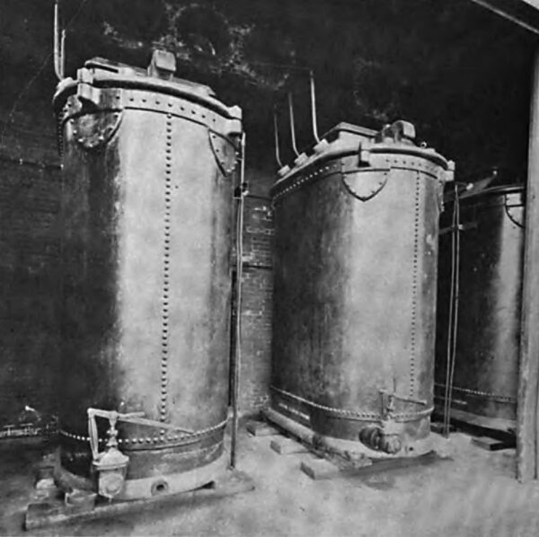
| The Massachusetts Street Substation, Seattle, Showing Three of the Six 2000-Kilowatt Transformers. |
There is in addition to the above apparatus, two 500-kilowatt transformers in this station with a ratio of transformation of 25,000 to 2200 volts, installed for connection to the transmission line of the Puget Sound Electric Railway.
For measuring the input of power into the 2300-volt busses a graphic recording voltmeter, ammeter and wattmeter are provided in addition to the integrating wattmeter.
| |||
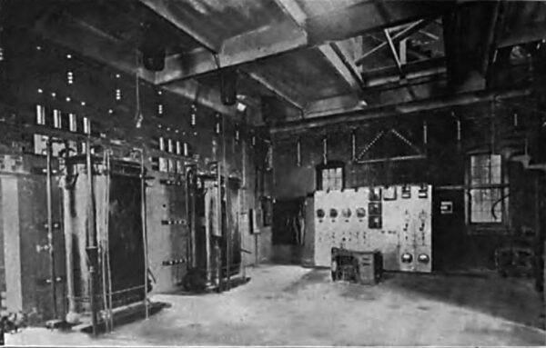
| The Massachusetts Street Substation Seattle, Showing the Switchboard and Compensators. |
Lightning arresters identical with those at the power house are provided for each of the incoming lines. Marble barriers between adjacent poles of the arresters are installed to prevent the travelling of an arc from one leg to another.
Four-pole static discharges are installed on the low tension side of each transformer bank, their purpose being the same as those at the power house.
For controlling the voltage of the 2300-volt outgoing feeders there is installed in each feeder a motor-operated induction regulator each of a capacity of 340 kilowatts.
These regulators boost or lower equally each leg of each phase.
The power is transmitted at 2200 volts, two-phase, from the Massachusetts Street substation to Post Street station, and from there also at 2200 volts, two-phase, to James Street station and Fremont substation.
| |||
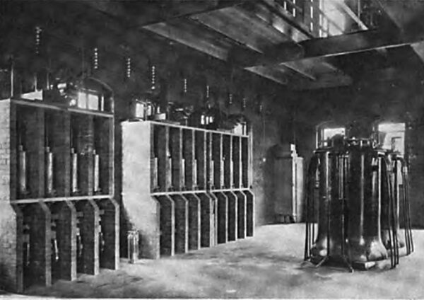
| The Massachusetts Street Substation, Seattle, Showing the Regulators and Low Tension Switch Cells. |
Post Street station contains nine 500-kilowatt rotary converters, each with two 300-kilowatt transformers, five giving 500-volt current for railway and four 250-volt current for lighting; also six 50-kilowatt tub transformers for street lighting. This station is a steam relay station and contains two 2500-kilowatt overload capacity, 60-cycle, 2200-volt, two-phase alternators, each driven by a vertical compound McIntosh & Seymour engine; also a 1000-kilowatt lighting and a 500-kilowatt railway battery. The station contains the general switchboard for controlling the whole distribution in Seattle.
James Street station contains two 300-kilowatt induction motor-generator sets giving 500-volt railway current. It is also a steam relay station, with three 150-kilowatt railway generators driven by a double Corliss engine. When operated on a water power basis the railway generators are used as motors to operate the James Street cable road.
Fremont substation contains two 300-kilowatt motor-generator sets, one induction and one synchronous, the motor end of each being 2200 volts, two-phase, and the generator end 500 volts direct current. There is also installed a 300-kilowatt railway battery.
The Seattle Electric Company has in addition to the above, two steam relay stations not used as substations. These are equipped with direct current machinery for railway and light and have a combined capacity of 1500 kilowatts.
The receiving station in Tacoma is a new brick building, built adjacent and as an addition to the steam station of the Tacoma Railway and Power Company. Control for two incoming high tension lines is provided as described for Massachusetts Street substation. One 4000-kilowatt, 50,000 to 2300 volts, transformer bank is installed with automatic oil switch control on high and low tension sides.
There are also installed two 500-kilowatt step-up transformers, transforming from 2300 volts, two-phase, to 13,800 volts, three-phase, for supplying power to Fern Hill substation, the Northern Pacific Railway Companys shops and other local consumption not within the range of economical distribution at 2300 volts. Automatic control of this bank is provided on the low tension side only by means of a type H, four-pole, motor-operated oil switch. Spare transformers for each of these banks are provided.
For receiving power from the 25,000-volt transmission line of the Puget Sound Electric Railway, four 200-kilo-watt oil cooled transformers, wound for 25,000 to 50,000 volts, stepping down from 25,000 to 2300 volts, are installed.
The high tension oil switches are installed on a steel concrete gallery twenty feet above the transformer room floor, the two line oil switches on a gallery at right angles to the length of the building and the transformer switch on a gallery parallel to the length and along the north wall of the building. Directly under the transformer oil switch are the transformers themselves. On the opposite side of the room and parallel to its length and four feet above the floor are the transformer 2300-volt oil switches.
One 400-kilowatt induction regulator similar to those installed in the Massachusetts Street substation controls the potential of the supply bus, being installed between the transformer bus and the supply bus. Apparatus for cooling the transformer circulating water is being installed somewhat similar to that at the Massachusetts Street substation.
The 2300-volt power is used for lighting and power service in the city of Tacoma partly and partly converted into 600-volt direct current for railway and commercial motor service. This conversion is effected by two 500-kilowatt induction motor-generator sets, by one 850-kilo-watt synchronous motor set and by 800 kilowatts in belted machines driven by a 1000-kilowatt synchronous motor. Either this synchronous motor or the 1000-kilowatt motor driving the 850-kilowatt direct current generator can be driven by the steam engines which drive onto a line shaft in which these motors are set, being connected at either end by jaw clutches, thus furnishing a supplementary source of supply and reserve for any of the alternating current distribution, and for the induction motor-generator sets supplying current for the railway. A 100 horsepower induction motor furnishes power for driving a cable road accommodating the hill districts of the city.
The Tacoma Railway and Power Company operates about eighty-four miles of track in the city of Tacoma and between Tacoma and the neighboring towns of Puyallup, Spanaway and Steilacoom, and also furnishes power for the operation of the trains of the Puget Sound Electric Railway within the Tacoma city limits.
At the Fern Hill junction of the Puyallup and Spanaway lines is a steam station of 500 kilowatts capacity. There is being installed in this station a 500-kilowatt synchronous motor-generator set, supplied from the substation above described by a 13,800-volt transmission line.
This same transmission line supplies current for the operation of motors and lights at the shops of the Northern Pacific Railway at South Tacoma and for the operation of induction motors driving air compressors working a Pohle air-lift system pumping water for the Tacoma city water supply, near South Tacoma, and for operating a large number of other stationary motors used by various manufacturing concerns.
The Puget Sound Electric Railway operates an interurban third rail system between Seattle and Tacoma traversing the White River Valley, a distance of thirty-six miles, and also a branch line reaching the town of Renton. Six-hundred-volt direct current is supplied to the third rail through three substations located at Georgetown, Kent and Milton.
Each substation contains a bank of transformers stepping down from 25,000 volts, three-phase, to 2300 volts, two-phase; also a 300-kilowatt induction motor-generator set and a storage battery having a rating of 384 kilowatts on the hours basis. Oil switch control is provided on both the high and low tension sides.
From Kent substation is operated the city lighting systems of Kent and Auburn, a transformer, separate from those feeding the motor-generator set, being provided for supplying this 2300-volt service.
These substations are supplied from the 25,000-volt transmission line previously mentioned, this line having the 25,000-volt transformer relay at both the Seattle and Tacoma ends. When this line is operated at 30,000 volts, transformers for this voltage will be installed in all the substations.
The electrical development has been designed primarily to insure uniform and uninterrupted service. Continuity of service has been insured by the greatest solidity of construction in every part; by duplicate busses and switches at the power house; duplicate transmission lines and spare transformers at each end of the transmission line so that all repairs can be made without discontinuing service, and by having in all the electrical machinery an overload capacity of from 25 per cent. to 50 per cent.
In addition to this there are in reserve in Seattle and Tacoma six steam plants of 10,000 kilowatts aggregate capacity and six storage batteries of 2700 kilowatts aggregate capacity, all electrically interconnected with each other and with the water power plant, and ready for supplementary and relay service.
