[Trade Journal]
Publication: The Journal of Electricity, Power and Gas
San Francisco, CA, United States
vol. 14, no. 9, p. 337-358, col. 1-2
The Guanajuato Hydro-Electric Transmission.
BY ROBERT McF. DOBLE.
THE accompanying sketch map, figure 1, shows the location of a notable hydro-electric power development and high potential long-distance transmission, recently completed in the States of Michoacan and Guanajuato, Republic of Mexico. This plant is a very interesting one, because of its many advanced engineering features, the remarkably short time within which it was constructed, and the fact that the work was completed within the estimates of cost.
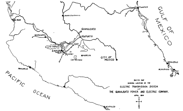 |
Under a concession from the Department of Encouragement, Colonization and Industry of the Republic of Mexico, the Guanajuato Power and Electric Company constructed a canal, pipe line, power generating station, transmission line, sub-station, and distributing systems for developing and marketing the energy of 8,000 liters (283 cubic feet) of water per second, diverted from the Duero River at the confluence of the Camecuaro and Chilchota Rivers, and returned above the Chaparacho Dam. The following are some of the distinctive features. The head works, canal and power-house are of massive and permanent construction. Special arrangements are made for regulating and measuring the water and for collecting and disposing of the detritus carried by the water during the rainy season. The pressure pipe is large, conducting the water at a low velocity. It has no horizontal bends, and only a few vertical bends, all made with long radii. It is bedded in masonry at each end and is laid in a deep trench and completely covered. It terminates at the bottom in branches leading directly to the water wheel nozzles. The nozzles are the largest yet used. The hydro-electric generating units have two 1,125 horse-power water wheels mounted directly or the ends of the generator shaft and overhanging the two bearings. Energy is transmitted at 60 kilovolts a distance of 101 miles, over 19-strand hard-drawn copper cables, carried on specially designed porcelain insulators larger than any heretofore used. It is the first long span steel tower transmission line.
| |||
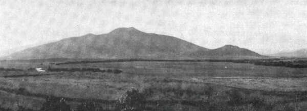
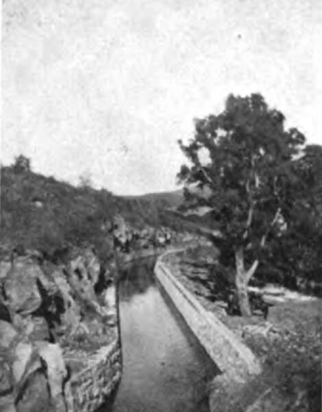
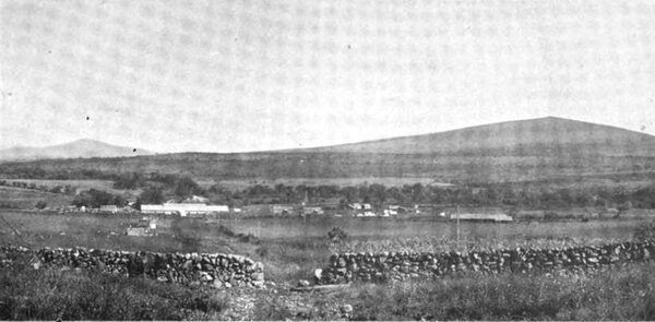
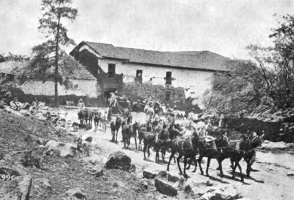
| Photograph No. 2. the Tangancicuaro Valley |
The inception and development of this enterprise are interesting. Some three or four years ago, Mr. Leonard E. Curtis, who had been for a long time counsel in patent matters for the Westinghouse Electric and Manufacturing Company, and who had been obliged to leave New York and go to Colorado on account of his health, was sent to Guanajuato by clients to examine the title to certain mining properties there. In the course of this examination he became interested in the place, and was impressed with the very high cost of the power used for mining operations. Being familiar with modern developments in long-distance electrical transmission, it occurred to him that the conditions there were exceedingly favorable for the introduction of electric power if a suitable water power could be found within working distance. He employed a young American, whom he found there, to search for a water power, giving him a radius of one hundred miles from Guanajuato to work in. The water power which has since been developed was found and an option obtained on it during the following year. In the meantime Mr. Henry Hine, under whose management the Stanley Electric Manufacturing Company had been built up, and who had resigned his position in that company when the ownership of it changed hands, had joined Mr. Curtis in Colorado, and the two had taken up the installation of power transmission plants together. After making a preliminary examination, they presented the matter to prominent capitalists at New York and Boston, who quickly subscribed the necessary capital, subject to an engineering examination. This examination was made by Mr. Robert McF. Doble of San Fran cisco, Mr. H. H. Filley of Kansas City, and Mr. Charles T. Main of Boston. Their report was favorable, and the company was organized and proceeded with the construction work. Mr. Filley was employed as Chief Engineer of the company, Mr. Doble as Consulting Engineer, and Mr. Norman Rowe, formerly with the Westinghouse Company, was put in charge of the construction work at Guanajuato, and now has charge of the plant as General Superintendent.
The designs and specifications were prepared in San Francisco. The iron work for the canal and the massive steel pipe-line were ordered from Messrs. Joseph T. Ryerson & Son of Chicago. The plates for the pipe-line were made in Germany, transported by sea to New Orleans, up the Mississippi River and by rail to Cudahy, Wis., and shaped and riveted in the new and finely equipped shops of the Holthoff Machinery Company there. The water wheels were constructed by the Pelton Water Wheel Company in the staid old Quaker City of Philadelphia. The electric generators and transformers were built at the great factory of the General Electric Company at Schenectady, New York. The transmission cables were shipped from the shops of the Ansonia Brass and Copper Company at Ansonia, Conn. The steel towers supporting the cables were manufactured by the Aermotor Company at Chicago. The insulators were made by the Locke Insulator Manufacturing Company at Victor, New York. The poles for the distributing circuits were bought in Texas, and the Portland cement for the masonry was brought in from Germany. From these various sources the materials came by sea and by land to the railway station at the quaint Mexican city of Zamora, whence they were hauled on wagons.
The watershed which supplies the Duero River has never been thoroughly explored. Its area is estimated at 400 square miles; it extends to the Continental Divide, and includes high timbered mountains and land-locked lakes. This portion of the State of Michoacan is a series of fertile valleys, lying one above the other, very like a series of vast terraces. The elevation is from 5,000 to more than 12,000 feet above sea level.
About ten miles to the south of the Zamora Valley, and about 400 feet higher in elevation, lies the broad, beautiful and fertile valley of Tangancicuaro, beyond which, to the south, at a greater elevation lies the valley of Los Once Pueblos (the eleven villages). The Tangancicuaro Valley is nearly surrounded by mountains, which toward the south are timbered and reach an altitude of from ten thousand to twelve thousand feet. Lake Patzcuaro, a large and deep lake with no known outlet, is located high up in this mountain range.
The entire area is of volcanic origin. The rain waters falling upon the high mountain lands penetrate the crevices in the basalt, slowly percolate to lower impervious strata, and then issue from the springs which abound in the valleys mentioned. The catchment area is so extensive and the distance which the water probably traverses so great that the subterranean reservoirs yield an exceedingly uniform volume through the numerous springs, which, during the dry season, furnish the entire volume of the Duero River. Such. geological formation and source of supply for a river of considerable and of uni form discharge is not without a parallel, though somewhat uncommon. Similar cases may be found in the lava districts of northern California.
The Duero River is formed by the confluence of the Camecuaro and Chilchota Rivers, which unite at the northerly edge of the Tangancicuaro Valley just above where a low ridge of basalt crosses between the neighboring mountains. Through a break in this formation the river commences its rapid descent into the Zamora Valley, about 400 feet below. The Chilchota branch, with its many tributaries, extends in several directions throughout the Tangancicuaro Valley and to the similar valleys terraced above it, notably Los Once Pueblos, where are located the Chilchota Springs. It has a very extensive watershed reaching to the high timbered mountains, and from it extensive irrigation is practiced. Hence during the rainy season it becomes a rushing torrent, and during the dry season the demands made upon it greatly diminish its volume. Its banks are closely lined with the sabino, or ahuehuete, trees (see photograph No. 4) and from an eminence its course can be plainly traced through broad wheat fields. (See photograph No. 2.)
The Camecuaro branch is only about a mile in length with practically no catchment area. It is supplied by a large group of springs, the water issuing from the lava formation on the northerly side of a low hill. These picturesque springs are surrounded by a fine grove of very large sabino trees (see photograph No. 3), which also closely line the banks and confine the stream within its meandering channel until it unites with the Chilchota. The Camecuaro branch has very little fall from its source to the Chilchota, and it is plainly evident that its volume is remarkably uniform throughout the year. No water is taken from it for irrigation, but at times it receives a small addition to its volume as a result of the excessive irrigation of the wheat fields lying above it with water brought through a ditch from another spring.
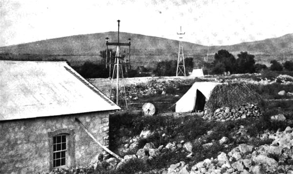
A number of careful current meter measurements were made, and compared with figures collected from every possible source, to determine the minimum discharge of the Duero River. Photograph No. 4 shows one of the gaging stations. This data led to the conclusion that there would never be less than a sufficient quantity of water available to warrant the construction of a generating plant of 8,000 electrical horse-power capacity. The possibility of increasing the low water flow by means of storage reservoirs located in the high mountains has not yet been fully investigated.
Between the point where the water is taken from the Duero River, namely at the confluence of the Camecuaro and Chilchota branches, to the point where it is returned to the river, namely at the Chaparacho Dam, there are three dams in the river for the purpose of diverting portions of its waters into irrigation canals for the ranches of La Rojena, La Planta and Tamandaro.
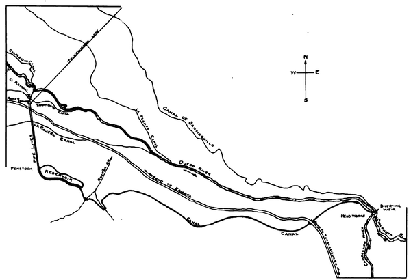 |
| Figure 5. Sketch Map of Canal, Showing Plan of Development |
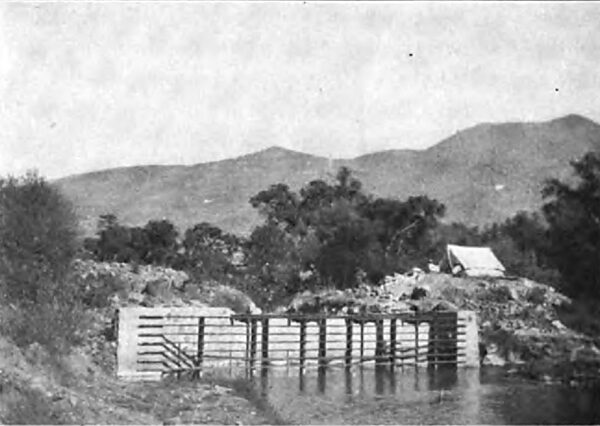
The accompanying plat (figure 5) of the river, canal, pipe-line, etc., shows clearly the general plan of development. The native dam shown in photograph No. 6 is in strange contrast with the type of construction now to be described.
The masonry diverting dam is built of volcanic rock, the interior being laid up with lime mortar, and the exterior with Portland cement. It is a curved structure, with a radius of 88.19 meters, the length of the crest being 80 meters. Its elevation is 1,662.40 meters above sea level. It is computed as a gravity dam for a maximum depth of 1.60 meters of water over the crest.
| |||
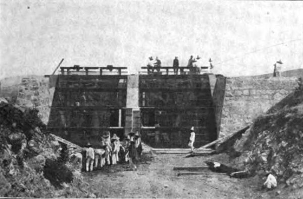
| Photograph No. 7. the Head Works From Up - Stream |
| |||
| Photograph No. 8. the Head Works From the Down - Stream Side |
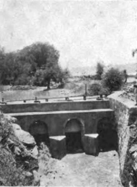
A heavy steel fender, securely braced against the masonry, protects the entrance to the canal from the drift brought down by the freshets during the rainy season. (Photographs Nos. 7 and 8.) Water is admitted to the canal through four head gates, each with an opening 1.25 by 2.00 meters, at a maximum velocity of about 0.80 meters per second. These head gates run in an angle iron frame set in the concrete. They are made of wood heavily ironed, and are operated through a worm gear which runs on the threaded gate stem like a nut. This worm gear nut is held stationary between ball bearings. The worm which turns it is provided with bronze thrust collars, and is mounted on a spindle having a removable hand crank at one end.
The canal is 6,650 meters long, is of trapezoidal section, 4 meters wide on the bottom and 2.10 meters deep. The side slopes are 1:1 in soft earth, 0.5: 1 in hard rock and 0.2: 1 where the canal is lined with cement. Its slope is uniform 1:2500. Its carrying capacity is 283 cubic feet per second at a velocity of between two and three feet per second.
| |||
| Photograph No. 9. the Rating Flume. |
| |||
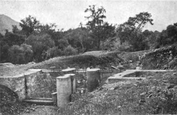
| Photograph No. 10. the Settling Basin and Submerged Weir, From Down - Stream, During Construction |
To provide for accurately measuring the volume of water allowed under the concession, a rating flume was constructed near the head works. It is about 100 feet of straight canal, lined with Portland cement held in place by sheets of expanded metal. The top of the wall on the side toward the river is finished with an adjustable metal weir (photograph No. 9), which is set so as to act as a spillway when more than the proper volume of water is flowing.
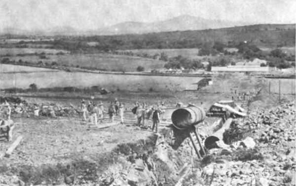
A short distance down stream, the canal is widened and deepened, causing a reduction in the velocity of the flowing water to about one-third of the normal, so that any sand may settle to the bottom. This settling basin (photograph No. 10) is provided with six valves opening from its bottom into a culvert which leads out from under the canal to the river. These valves are of new and interesting design, consisting of a circular cast iron opening 18 inches in diameter, closed by means of a conical cast iron bell, drawn point up into the opening from below, and held there by means of a threaded stem and nut, which rests upon two channel beams spanning the canal. By turning the nut the cast iron bell may be lowered to open the valve and wash out the sand which has collected at the bottom.
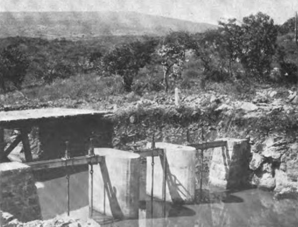
Immediately below the settling basin there is an adjustable submerged weir, shown quite plainly in photograph No. 11. By means of the head gates and by the adjustable lip at the rating flume, in conjunction with the sub merged weir, the quantity of water flowing in the canal may be closely regulated.
At the time the photographs were taken there was very little water flowing in the canal, as it was being filled for the first time to test and to furnish water for puddling the canal.
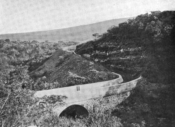
From this point the greater portion of the canal is of the character shown in photographs Nos. 12 and 13. It meanders along the southerly side of the canyon; under a substantial masonry arch road bridge, 33 feet wide and 16 feet span; over a massive masonry aqueduct, photographs 14 and 15; to a spillway, and thence to a second sand trap (photograph No. 16), near the forebay. The spillway and second sand trap are located so as to make use of the Barranca de la Rojena as a waste waterway leading to the Duero River.
| |||
| Photograph No. 14. the Massive Masonry Aqueduct |
| |||
| Photograph No. 15. Inside the Masonry Aqueduct |
| |||
| Photograph No. 16. the Lower Sand Trap at Kilometer Post 6 |
| |||
| Photograph No. 17. the Storage Reservoir |
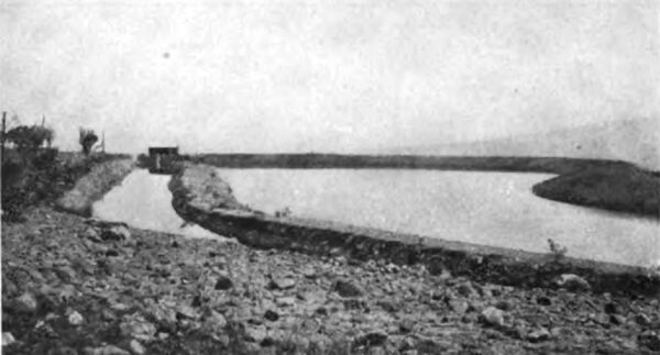
A small storage reservoir (photograph No. 17) is constructed alongside the canal at the forebay, by means of which a sufficient reserve of water is maintained to admit of cleaning the canal when required, and also to carry a very considerable peak load in excess of the normal capacity of the canal.
A simple arrangement is provided for allowing the surplus water to flow into the reservoir from the canal during the hours of light load, and during that time to maintain the maximum head or pressure on the pipe line, regardless of the elevation of the water in the reservoir.
Four suitable automatic gates, like flap valves, are placed in the reservoir, near its bottom, opening outwards into the forebay. So long as the supply of water in the canal is equal to or in excess of the discharge through the water wheel nozzles in the power house, the maximum water level is maintained in the forebay; if there is a surplus of water, it overflows from the forebay into the reservoir over a suitable weir. Whenever the requirements of the water wheels are in excess of the quantity of water flowing in the canal, the water level in the forebay is lowered, relieving the pressure on the outside of the automatic gates, which then open and let the reservoir discharge to make up the deficiency. At the entrance to the forebay the water passes over a measuring weir. On passing from the forebay to the penstock the water flows through a screen (photograph No. 18), which removes all floating debris.
| |||
| Photograph No. 18. the Massive Masonry Penstock and Screen During Construction |
| |||
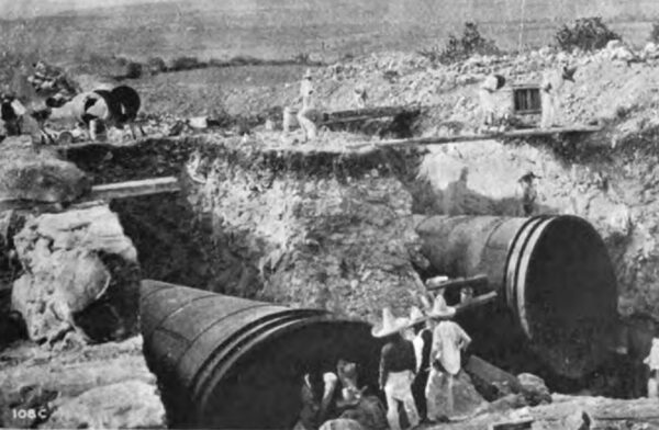
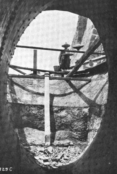
| Photograph No. 19. Placing the Great Oval Taper Sections |
| |||
| Photograph No. 20. Looking Out Through the Mouth of the Great Oval Taper Section During the Construction of the Penstock |
| |||
| Photograph No. 21. Boilermakers at Work in the Field, Riveting Up the Pipe |
The massive masonry penstock is strengthened by iron hoops embedded in its walls, and is interesting because of its excellent hydraulic lines. The water, after passing through the screens and through four gates similar to those at the head works, enters two ellipsoidal masonry basins, which gradually diminish in diameter toward the bottom, merging into the great oval taper sections, which are the heads of the pipe lines (photographs Nos. 19 and 20). This design causes a gradual acceleration in the velocity of the water and also prevents the formation of the whirling vortex which would draw air into the pressure pipes. The pipe line is 3,300 feet long, with no lateral bends. It varies in diameter and thickness, as shown in the following table, and was designed with a safety factor of five.
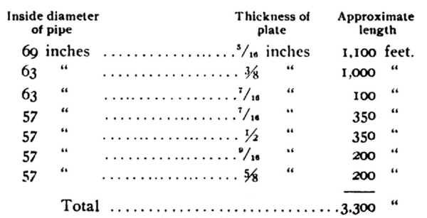 |
The decrease in the diameter of the pipe sections causes an acceleration in the flow of the water as it descends. This also made possible the nesting of sections for shipment.
The pipe was made up from steel plates, in sections 27-1/2 feet long, and weighing from 7,000 to 10,000 pounds each. The steel plates were carefully selected and tested, the metal being required to have the following characteristics:
Tensile strength: 52,000 to 62,000 pounds per square inch.
Elastic limit: Not less than one-half the tensile strength.
Elongation: 25 per cent.
180 degrees cold quench bend flat on itself without fracture on the outside of the bent portion.
There are 480 separate plates in the pipe, each rolled tapering, the small end of one fitting inside the large end of the one next below it.
All seams were lapped, and the longitudinal seams were designed so as to have at least 70 per cent of the strength of the plate. These longitudinal seams were placed so that they are on top of the pipe and alternately opposite, with the caulking edges up, as shown in photograph No. 21. The longitudinal seams are double riveted; the circular seams single riveted. All the shop riveting was done by a large hydraulic riveter. The field riveting was done by hand by a gang of expert boiler makers sent to Mexico for that purpose. Two riveters, a helper and a man at the forge to heat the rivets could finish one circular seam in a day. When riveted the pipe was caulked and an extra coat of preservative paint was applied. Each section of the pipe had on top near its lower end a hole through which the hot rivets were passed from the forge to the man inside. The hole was tapped and a plug screwed in after the joint was riveted (see photograph No. 21). Each section was plainly marked at the factory with letters indicating its position in the pipe line.
| |||
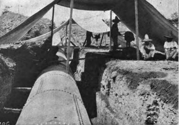
| Photograph No. 22. Laying the Pressure Pipe |
The common practice of laying pipes of this character on top of the ground and supporting them on piers was not followed. A deep trench was dug, the bottom of which was graded on long tangents and with slight vertical angles. The pipe was laid in this trench beginning with the section nearest the power house, and riveting on section after section, working up hill. Bell holes were dug in the bottom of the trench so that the riveters might have room to swing their hammers. The back filling of the trench was done with great care, the earth being dampened and thoroughly tamped under and around the pipe. During the early morning hours, while the pipe was cool and at its minimum length, the top covering was completed (see photograph No. 22).
On August 24, 1903, the pipe was tested, and so well had the work been done that not a single leak was found, although there are over 70,000 rivets.
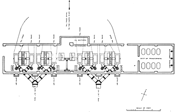 |
| Figure 23. Plan of Generating Station |
The pressure pipe terminates at the bottom of the hill in branching cast iron pipes leading through the south wall of the power house to the nozzles, as shown on the plan, figure 23.
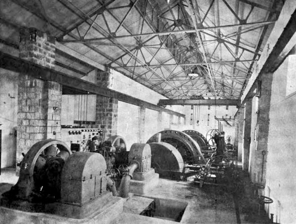
The power house (photographs Nos. 24 and 25) has masonry walls, built of native volcanic rock. The roof is of galvanized iron supported by steel roof trusses and lined with an anti-condensation lining.
| |||
| Photograph No. 24. the Power House From Part Way Up the Pipe Line. El Platanal to the Left. the Construction Camp to the Right. Transmission Towers Reaching Into the Distance |
| |||
| Photograph No. 25. the Power House From the Northeast |
As shown by the photographs, it is built in an excavation extending to a considerable depth below the natural surface of the ground. This was done for economical reasons. The pipe line profile is quite flat at the lower end where the pipeline is the thickest and most expensive, and it was concluded that it would be cheaper to excavate a longer length of tail race and to dig deeper for the power house than to extend the pipe line, as each additional foot on the 57-inch pipes 54 inch thick would cost a considerable amount. The inside dimensions of the power house are: length, 200 feet; width, 32 feet. The floor is of cement. A low wall separates a length of 40 feet at the easterly end of the building, where the transformers are placed (photograph No. 26), which portion is two feet lower than the main room, and is provided with drains into the tail race.
| |||
| Photograph No. 26. Interior of the Power House, Looking Easterly |
There are two ten ton hand operated cranes which run the entire length of the building over both generator and transformer rooms. The erection of these cranes was an unusually simple matter. They were rolled into place from the surface of the ground and subsequently constituted the basis of a moveable platform upon which the roof trusses were carried to place.
The cast iron branch pipes convey the water to heavy 30 inch gate valves equipped with by-passes. The nozzles are attached to the gate valves as shown in the accompanying plan (figure 23). These pipes are made of close grained gray cast iron and have lip and recess bolted flange joints with lead gaskets and are entirely buried in concrete.
As shown in the plan, the nozzles are curved in form making a 45 degree bend so as to bring the axis of the jet at right angles to the water wheel shaft. Each nozzle is provided with a removable tip, of cold blast char coal iron, held in place by means of 14 seven-eighths inch Tobin bronze studs with steel nuts. The nozzle is of the needle regulating type having a core piece moveable axially within it by means of which the annular area of the orifice is changed. The core piece is a Tobin bronze stem with a phosphor bronze bulb fitting into the nozzle tip. A continuation of the stem through a gland in the convex side of the nozzle casting is threaded, and, by means of a bevel gear nut operated through a hand wheel stand the needle is moved in and out to adjust the quantity of water discharged by the nozzle, so that the maximum economy in the use of water may be attained. This construction produces a solid jet of good form and of high efficiency over a wide range of discharge. Each nozzle is equipped with a deflecting hood, operated through a system of levers by a governor, for regulating the speed of the generating unit.
| |||
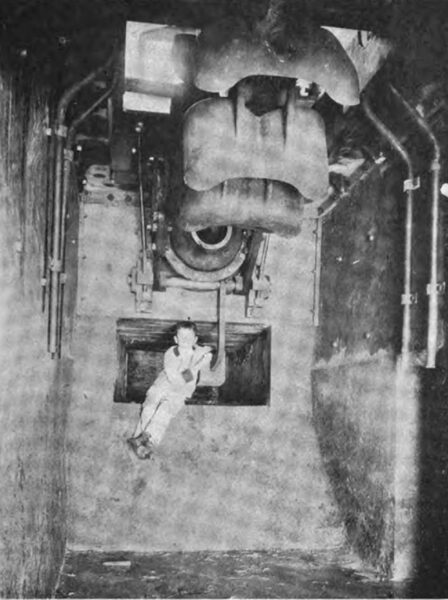
| Photograph No. 27. A Water Wheel From Underneath , Showing Air Inlet |
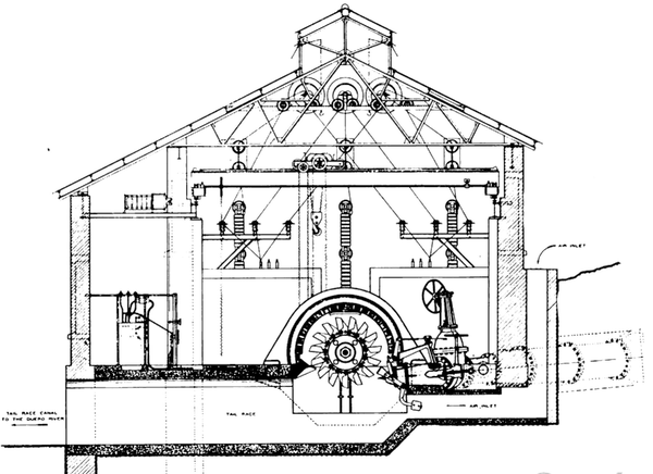 |
| Figure 28. Cross-Section of Generating Station |
| |||
| Photograph No. 29. the Discharge Into the Tail Race Canal |
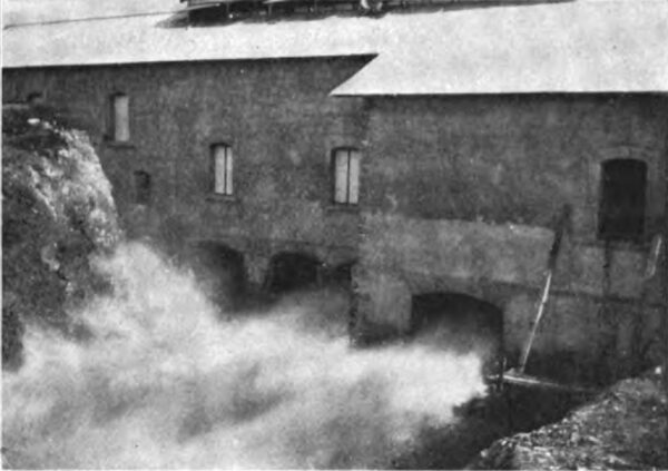
The water emerging from the nozzle tips in solid jets more than half a foot in diameter, at a velocity exceeding a mile and a half per minute, with a pressure of 138 pounds per square inch, is projected into the buckets of the water wheels (photograph No. 27; also cross section of generating station, figure 28). The discharge into the tail race is shown in photograph No. 29.
Each water wheel has fifteen huge buckets, more than two feet in width and weighing 254 pounds apiece, made of close grained cold blast charcoal iron. The buckets are accurately fitted to the rim of the cast iron wheel centre and secured thereto by means of two fitted steel stud bolts. The entrance edges are sharpened, the hydraulic surfaces are ground smooth and painted and each bucket is brought to a standard weight so as to obtain a dynamic balance. The cast iron wheel centers are machine finished all over, bored taper, keyseated, and secured to the projecting ends of the generator shafts by means of a feather and a large bronze nut, as shown by the longitudinal partial section, figure 30.
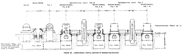 |
| Figure 30. Longitudinal Partial Section of Generating Station. |
The solid carbon steel shaft is 12 inches in diameter from the water wheels through the bearings; being enlarged to 16 inches diameter in the middle portion. The bearings are 36 inches in length by 12 inches in diameter, of ring oiling water cooled type of special design.
The generators are revolving field, engine type, 2300 volt, 3 phase, 60 cycle, 200 R. P. M. machines, rated at 1250 K. W. but designed for a 25 per cent continuous overload. Their characteristics, as determined by factory test, are as follows:
Full load commercial efficiency...... 95-77%.
Three-fourths load 94.92%.
Regulation at full load and 100% power factor is 4.4%, temperature rise of armature 21° centigrade after six hours full-load operation.
The total weight of the revolving element consisting of the field, the shaft and the two water wheels, is about 50,000 pounds, carried on two bearings. The speed is regulated by means of a governor, operated by an oil pressure system, actuating the deflecting hoods already described. The governors and the oil pressure pumps are bolted from the generator shaft, as shown in photograph 31.
| |||
| Photograph No. 31. Interior of Power House, Looking Westerly |
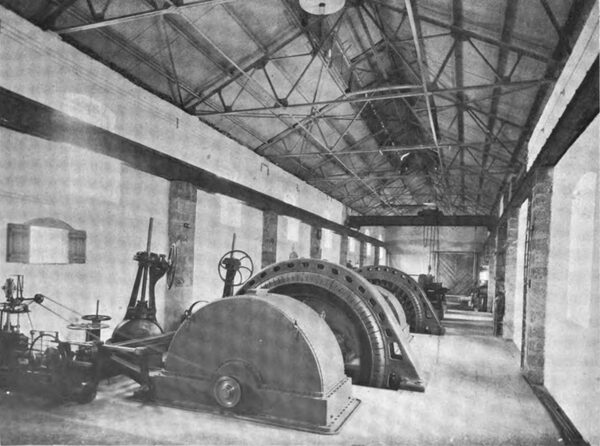
The hydro-electric generating units above described are conspicuous by reason of their compactness and simplicity, there being only the stationary armature, the electric and hydraulic revolving elements mounted on the shaft, and two bearings. The 1250 K. W. unit occupies a floor space of only about seventeen feet by twenty-five feet (photograph No. 32).
The assembling of such heavy machinery remote from shop facilities presented some difficulties, and in photograph No. 33 is shown the method employed for pulling on the revolving field spider and the water wheels, by use of specially long threaded steel bolts.
Continuous current for exciting the alternators is sup plied by two 120 K. W. 500 R. P. M. self-contained hydro-electric units, each of sufficient capacity to excite the four generators; so that one exciter is a spare. The exciter base is extended so as to receive the water wheel housing (photograph No. 26). The water wheel is mounted on the extended end of the shaft overhanging the bearing. Water is supplied to the wheel through a hand regulating needle nozzle, being conveyed from the main branch pipe as shown by the plan, figure 23.
The current is conveyed from the generators to the switchboard, and thence to the step-up transformers, through lead covered rubber insulated copper cables laid in shallow covered ducts in the cement floor. The current passes from the generators through 600 ampere oil break switches, each installed in a separate concrete compartment, to the 2300 volt bus-bars.
The field rheostats are supported on 4-inch I beams above the switchboard and are operated by means of chains and sprocket wheels. The bus-bars, oil switches, and wiring for the instruments are all back of the board and out of the way being located in an alcove on the north side of the building, as shown in the plan, figure 23, and in photographs Nos. 26 and 32. The switchboard has seven marble panels, one for each of the generators, one for each exciter and one for two step-up transformer circuits.
From the switchboard the 2300 volt current is conducted to the 1080 K. W. static transformers where the potential is raised to 60,000 volts for transmission. The transformers are Delta connected on the low potential side and Y connected on the high potential side, having taps brought out through the top of the tank for line potentials of 40,000, 50,000 and 60,000 volts, the neutral being grounded. The efficiencies of the transformers as determined by factory tests are as follows:
Full load 98.295%
Three-fourths load .98.028%
The transformers are of the oil insulated water cooled type; the tanks are 9-1/2 feet in height and occupy a floor space of three feet by six feet. From the step-up transformers the current is conducted to the transmission line, the wires passing out of the building through circular openings in the wall to a set of 60,000 volt disconnecting switches mounted just outside of the building and thence to the first tower of the transmission line as shown in photographs Nos. 25 and 34.
| |||
| Photograph No. 34. the Transmission Line Reaching Away Toward Guanajuato |
On the inside wall of the building three rows of 60,000 volt lightning arresters are mounted, being connected through switches to the outgoing leads, as shown in photograph No. 26.
The 101-mile 60,000-volt transmission line differs materially in design from any line heretofore constructed, notably in the use of a hard drawn copper cable instead of the usual solid conductor, metal pins, cross arms and towers for supporting the insulators, and unusually long spans.
From the power generating station near Zamora the line passes for about 30 miles over rough mountainous lava formation cut by deep ravines. Near Guanajuato also there is some rough country but for about 60 miles the line passes over clear rolling country the most of which is under cultivation.
| |||
| Photograph No. 37, Making A Joint in the Transmission Cable C. Splice Completed |
The conductors are 19 strand, hard drawn copper cables, approximately 3/8 of an inch in diameter, equivalent in carrying capacity to a No. 1 B. & S. G. wire, and weighing 1340 pounds per mile. This type of conductor was finally determined upon, after much study and many tests because of its high conductivity, flexibility and mechanical strength; the wires composing it having a tensile strength of over 55,000 pounds per square inch. The cable was made and shipped in lengths of about two miles. The joints were made with special copper tube connectors 12 inches long and elliptical in cross section. The two ends to be joined were passed through the connector in opposite directions and three complete twists were given by means of special wrenches. Photographs Nos. 35, 36 and 37 show the making of a joint. No soldering was done. The cables are placed in grooves on top of the insulators, 78 inches apart, at the points of an equilateral triangle, and are tied in with No. 14 soft cop per wire, it being considered that the small wire wrapped about several times would make an easy tie and not be apt to damage the small, hard drawn strands of the cable.
The cable was shipped on reels in lengths of about two miles. Where the topography and roads permitted six of the reels were delivered from the wagons each four miles. The cables then were pulled out over the cross-arms on rollers and spliced and tied in. In the mountainous sections the cable had to be cut into shorter lengths.
| |||
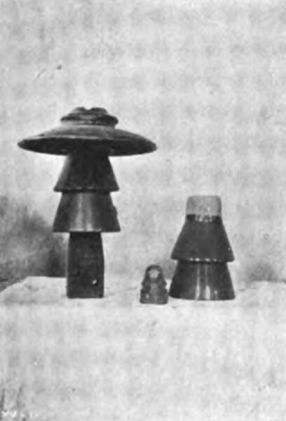
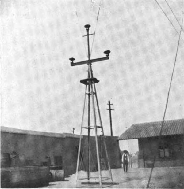
| Photograph No. 38 the Insulator and Cross-Arm Pin |
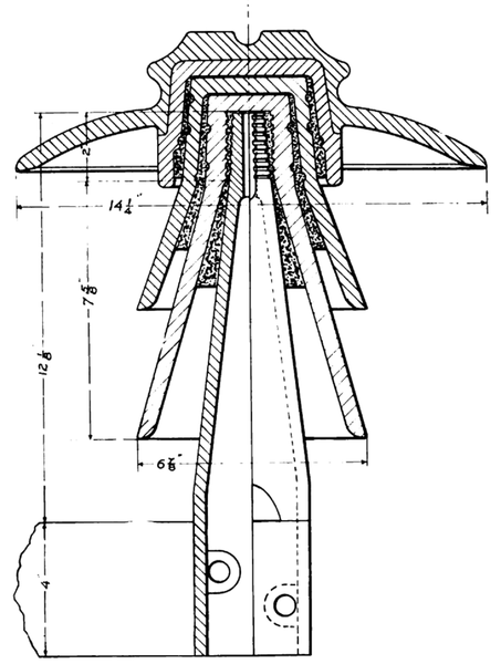 |
| Figure 39. Cross-Section of 60,000 Volt Insulator and Pin |
Diagrams showing the proper sag to be allowed at various temperatures and for spans up to 1320 feet, were prepared, based on a maximum strain of 20,000 pounds per square inch, in the coldest weather and with the most severe wind. The calculations include an allowance for the mechanical elasticity of the cable.
The insulators, photograph 38, are larger, heavier and better than any heretofore used and were required to stand a test potential of 120,000 volts for five minutes. They are over 12 inches in height and 14 inches in diameter and weigh about 15 pounds. They are made of porcelain with a brown glaze and consist of four parts, as shown in the cross section, Figure 39. The top and the first petticoat were glazed together in the kiln and the other two joints were made with neat Portland cement. The pins were likewise secured into the completed insulator.
The pins are of cast iron, conical in shape and cored hollow. The pin which carries the top insulator has an enlarged base, threaded on the inside, and is screwed on to the end of the 3-1/2 inch extra heavy pipe, which projects from the top of the tower.
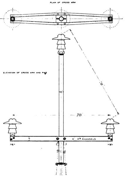 |
| Figure 40. Sketch of Top of Tower, Showing Crossarm and Pipe |
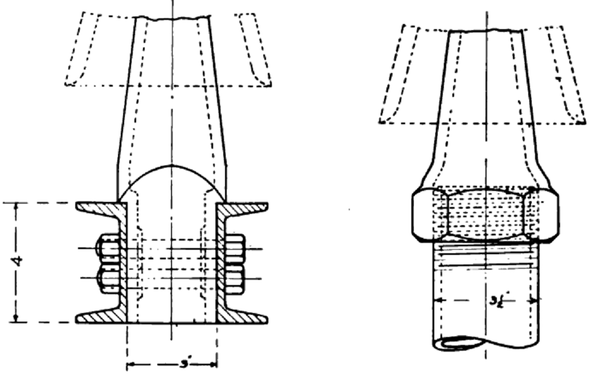 |
| Figure 40a. Detail of Pin Bases |
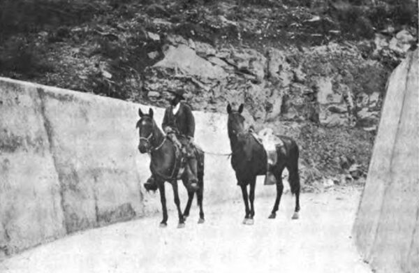
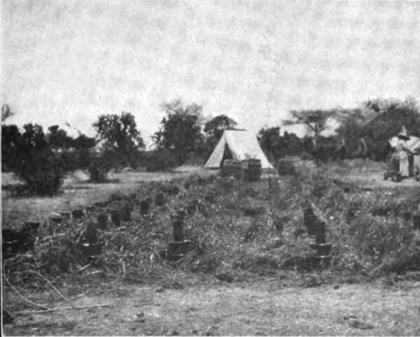
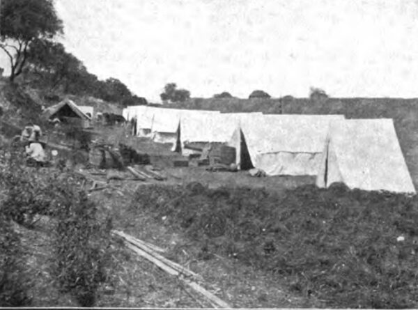
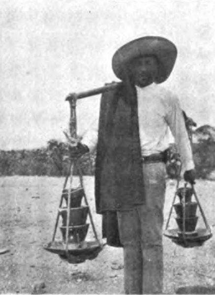
The pins which carry the lower insulators have rectangular bases, as shown in photograph No. 38, which are securely clamped between the ends of the four inch channels which constitute the cross-arm, as shown in the sketch of the top of the tower, figures 40 and 40A. The insulators were shipped in two parts, in barrels, and the cementing together of the parts and the cementing in of the pins had to be done in the field. The method employed is illustrated by photographs Nos. 41, 42 and 43. After the parts were assembled the field was covered with the packing straw from the barrels in order to protect the insulators from the hot sun while the cement was hardening. The completed insulators with the pins in place were then carried out from the construction camps to the required location on the line, two at a time, by man power as shown in photograph No. 44. This was found to be the most satisfactory and economical method, as human labor is very cheap in Mexico.
| |||
| Photograph No. 41. Cementing Together the Insulator Parts and the Pins. A. Ready for the Neat Cement |
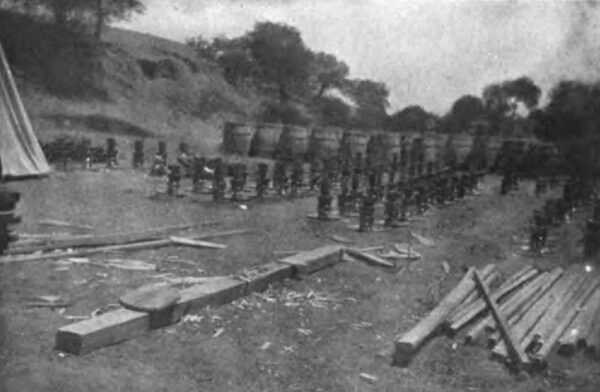
| |||
| Photograph No. 42. Cementing Together the Insulator Parts and the Pins |
| |||
| Photograph No. 43. After the Insulator Parts Have Been Cemented Together, They Are Dried in the Shade of Their Own Packing Straw |
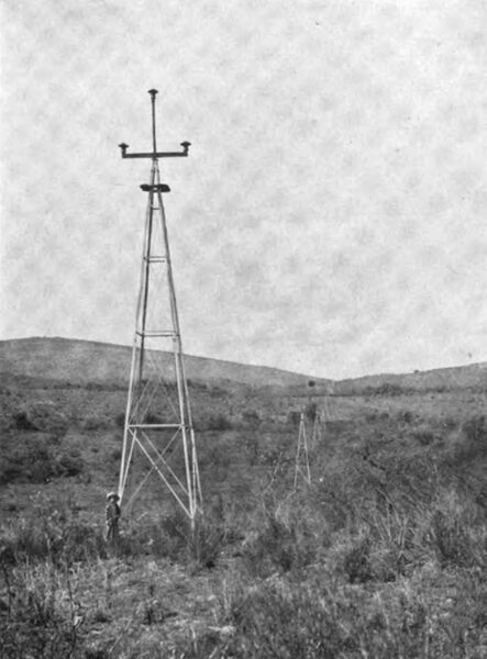
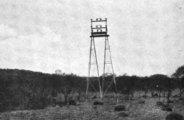
The towers, photograph 45, are special 40-foot four-post galvanized steel structures weighing about 1,500 pounds, made of 3x3x3-16 in. angles, braced and stayed with smaller angles and rods. Each post terminates in an anchor consisting of a piece of angle iron 30 inches long, secured at right angles. The construction is clearly shown in the drawing of the tower, figure 46.
| |||
| Photograph No. 44 Carrying Out Insulators Along the Line |
| |||
| Photograph No. 45. Transmission Towers Erected, Power Cables Strung |
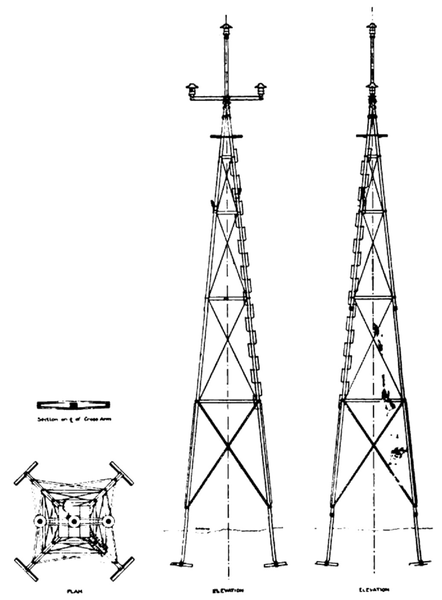 |
| Figure 46. the Transmission Tower |
A 40 foot tower with the 3% in. extra heavy pipe fixed in position at the apex, was built for testing at the factory of the Aermotor Co. This tower was bolted in its assembled state to the 30 in. wall of a five story brick building; so that its axis was horizontal instead of vertical as normally, a rope sling was attached to the pipe 70 inches above the apex of the tower, and to this a wooden plat form was attached. Weighed masses of pig iron were then placed upon this platform and the deflections of pipe and tower noted. When the load amounted to goo pounds the pipe began to show signs of yielding, the tower, however, was perfectly rigid. When the load was 1234 pounds, the deflection of the pipe from a straight line amounted to about 6 inches. On removing the load a permanent deflection of about 1 inch was found. The load was replaced and increased about 70 pounds at a time. With each increase the pipe took an additional permanent set, and at a load of 1560 pounds, it continued to bend until the load rested on the floor.
| |||
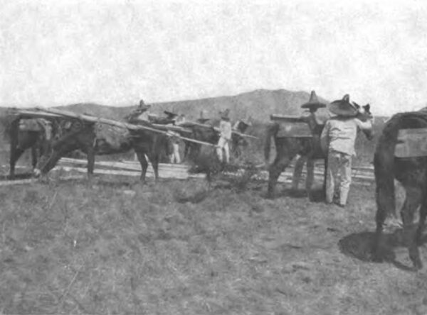
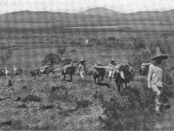
| Photograph No. 47. Loading the Pack Animals |
| |||
| Photograph No. 48. Transporting Tower Parts Through the Fields |
| |||
| Photograph No. 49. Assembling A Transmission Tower |
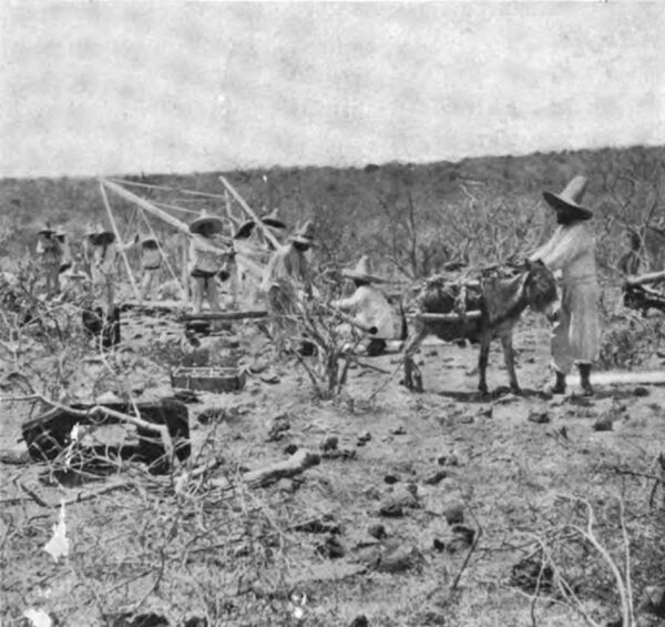
The transportation and distribution of the towers was carefully planned and very satisfactorily carried out. The necessary quantities of parts were shipped to the several railway stations which had been selected as centers for the distribution along the line. From the rail way stations the towers were hauled in wagons to convenient points on the highway and then were transported piecemeal through the fields on pack animals to the proper places on the transmission line ; some of the longest pieces being carried by two burros in tandem. See photographs Nos. 47 and 48.
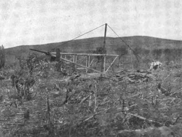
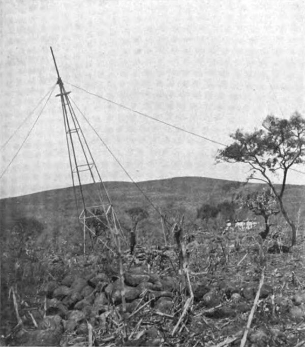
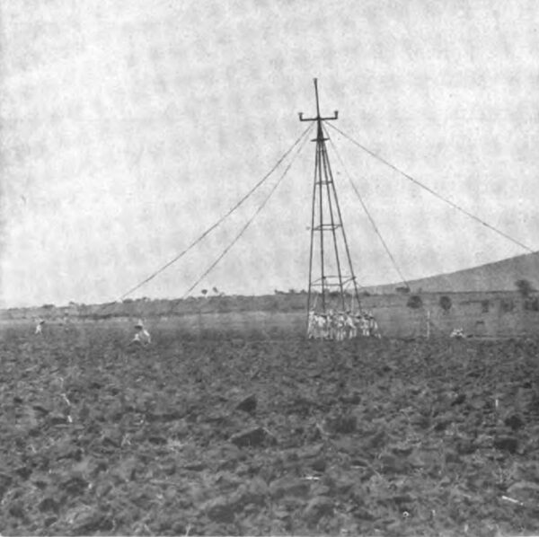
The assembling and erecting of a tower in place required skill and care. A gang of six Mexicans could assemble three towers a day. This was done with the tower lying on the ground, as shown in photograph No. 49. A gang of twelve Mexicans under an American foreman could easily erect twelve towers a day in the manner shown in photographs Nos. 50, 51 and 52.
| |||
| Photograph No. 50. Erecting A Transmission Tower |
| |||
| Photograph No. 51. Erecting A Transmission Tower |
| |||
| Photograph No. 52. Erecting A Transmission Tower |
The all metal construction of the supports for the transmission line was determined upon only after very thorough study and analysis and with a full realization of the fact that the insulators must then be of the most reliable and ample construction. The quality and suitability of the insulators were, therefore, carefully looked after.
The advantages of long spans, with consequent reduction in number of supports and of insulators required, were so obvious that it was at once decided to adopt that type of construction.
After careful study and many calculations and estimates the 40 foot towers spaced twelve to the mile were determined upon. The towers are spaced 440 feet apart, twelve per mile, except near Guanajuato where the nature of the ground necessitated the use of a few sixty foot towers and spans up to 1320 feet in length.
Two No. 9 B. B. double galvanized iron wires for a telephone circuit are fastened on the transmission towers ten feet below the copper power cables. They are tied to regular glass insulators placed on 12 inch painted oak brackets bolted to tower legs. The telephone wires are transposed one complete revolution every four towers; the power cables are not transposed. High resistance instruments are used, and the telephone service is quite satisfactory.
| |||
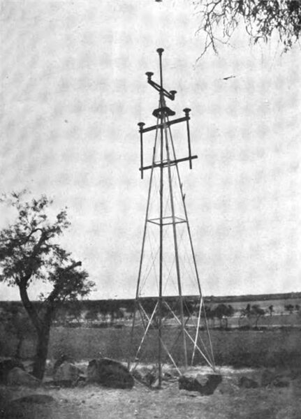
| Photograph No. 53. the Lightning Rod That is Being Installed |
The climatic conditions for high voltage transmission are usually good and during the dry season when the water is lowest, and when all the losses should be kept at a minimum, the atmospheric conditions are very favorable. Once or twice insulators at the top of the pole have been shattered, possibly by lightning. Photograph No. 53 shows a form of lightning rod that is being put on a number of the most exposed towers.
The long line of shining galvanized steel towers will catch the eye of the traveler as the train nears Palo Verde on the Guadalajara branch of the Mexican Central Railroad, or on approaching Irapuato on the main line from the north, at which points the transmission line crosses the railroad. It is almost straight, there being only a few slight horizontal angles.
| |||
| Photograph No. 54. Disconnecting Switches in the Main Line |
| |||
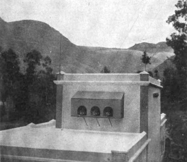
| Photograph No. 55. the Transmission Cables Entering the Guanajuato Sub - Station |
The line is divided into four sections of about twenty five miles, and is in charge of a superintendent whose headquarters are at the middle storehouse. At each of the three division points there is a first-class storehouse, a set of 60,000 volt disconnecting switches in the main line, photograph No. 54, a line foreman and patrol man both mounted. In the middle of each section there is a second-class storehouse in the care of a mounted patrol man.
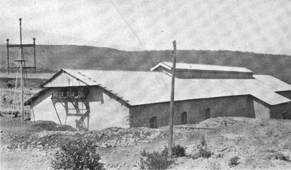
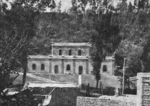
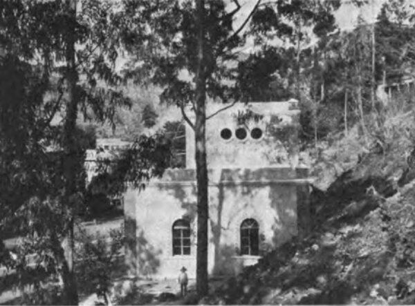
At Guanajuato the transmission line cables enter the sub-station through a set of 60,000 volt disconnecting switches, the same as at the generating station (photo graph No. 55). The Guanajuato sub-station is a handsome stone build ing with brick trimmings and a flat roof, standing in a beautiful grove of trees. Photographs Nos. 56 and 57. The dimensions of the building are, length, 113 feet, width, 89 feet. There is a central portion two stories high with well-proportioned one-story wings on either side. One wing contains an office for the general manager, a drafting room, an accounting room and a reception room. The other wing is fitted up for a repair shop and store room. The central portion contains the transformers. A 10 ton hand operated crane runs over the shop and transformer room; passing through folding iron doors.
| |||
| Photograph No. 56. the Guanajuato Sub-Station From in Front |
| |||
| Photograph No. 57. the Guanajuato Sub-Station From the Side During Construction |
The electric current enters the building, passes a set of lightning arresters with disconnecting switches, like those at the generating station, and goes to a bank of oil insulated water cooled transformers where the line potential is reduced to 15,000 volts. These transformers are rated at 970 K. W. each. Their efficiencies as determined by factory test are as follows:
Full Load 98.193%
Three-fourths load 97.93%
From the step-down transformers the cables pass through ducts under the floor to the switchboard, thence to the six 15,000 volt 3-phase distributing circuits, each of which is equipped with lightning arresters, and air break switches with tube fuses.
The solid copper wires of the distributing circuits are carried on 5-1/4 inch brown porcelain insulators, supported on wooden pins in wooden cross-arms on square yellow pine poles, 30 to 35 feet in height, 9 in. x 9 in. at the butt, and 7 in. x 7 in. at the top. The iron telephone wires are carried on the same poles but are frequently transposed. The power wires are not transposed.
At the mines and mills where the electric power is used the potential is reduced in three-phase transformers from 15,000 volts to 460 volts for motor service. The Guanajuato city 2-phase, 2100 volt lighting system 1s supplied through a bank of 150 K. W. 3-phase to 2-phase transformers with a feeder regulator in each phase.
| |||
| Photograph No. 58. Method of Joining the Irapuato Branch Line to the Main Transmission Line |
| |||
| Photograph No. 59. the Irapuato Sub-Station |
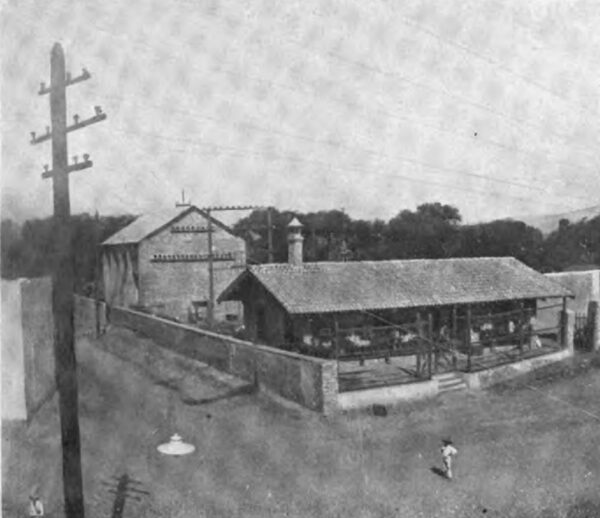
Photograph No. 58 shows where a branch line leads from the main transmission line to Irapuato, the Strawberry Station on the Mexican Central Railway. The Irapuato sub-station (photograph No. 59), is a brick building equipped with 60,000 volt disconnecting switches and lightning arresters and the following oil insulated air cooled transformers:
Four 200 K. W. line potential to 15,000 volts.
Four 75 K. W. 15,000 to 460 volts for motor service.
Two 40 K. W. 15,000 to 2200 volts for the city lighting system.
Power is supplied to various small industries throughout the city, including three grist mills, a foundry, a wagon works, a paint factory and various pumps used in irrigating the strawberry fields.
| |||
| Photograph No. 60. the City of Guanajuato, Mexico |
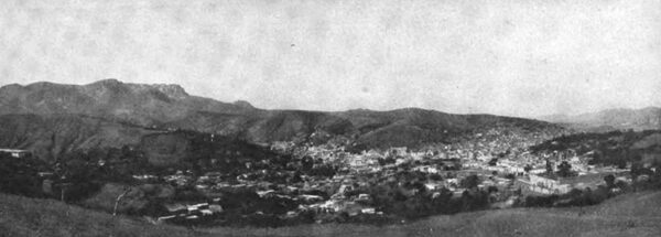
To the ingenuity of the American engineers, backed by American capital, is due this noteworthy development by which the energy of the swift and boisterous Duero River has at last been harnessed and after conversion into electricity has been transmitted over the 100 miles of intervening country to revivify the mining and other industries of the picturesque old city of Guanajuato (photo graph No. 60), famous for its great mines which are said to have produced, during the past 350 years, about one-fifth of all the silver in the world. Of late years these mines have not been worked to any great extent, largely because of the high cost of power.
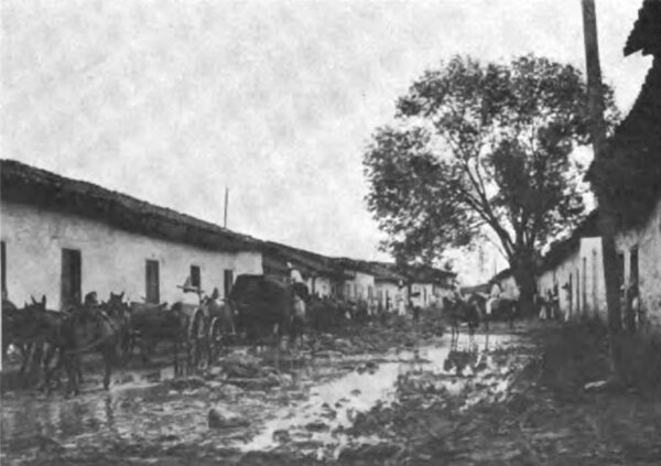
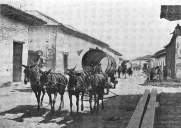
There were many interesting, as well as difficult features, connected with the construction work. The task of hauling to the construction camp was by no means easy, although the distance was not more than ten miles. The way lay through the city of Zamora, thence to the little town of Jacona and thence about six miles along the State highway to the construction camp at the little Indian village of El Platanal, where the power generating station is located.
American mules were purchased and specially designed American wagons were provided in order that adequate means should be at hand for carrying the heavy parts to their places.
| |||
| Photograph No. 61. Part of the Procession Formed to Haul One - Half of A Generator Armature Through the Streets of Zamora |
| |||
| Photograph No. 62. the Team of Twenty - Two Mules Hauling One - Half of A Generator Armature |
The roads through the country are mostly over black adobe soil of indefinite depth and a few rainy days are sufficient to convert such roads into regular quagmires. The haul through Zamora and Jacona was by far the worst part, since the streets had been improved (?) by a pavement of stones of no small diameter, and in spite of the wide tires the wagons would break through the pavement into the underlying mud during the short intervals of time allowed for the animals to rest. Photographs Nos. 61 and 62 show a team of twenty-two mules hauling the lower half of the armature of one of the generators, a load weighing 20,000 pounds. To get this load safely over the city streets required the combined efforts of two American superintendents and ten peons, all directly interested in some way in the moving of the load. Two wagons followed carrying jacks, block and tackle, and tools for making repairs enroute, forming in all quite a procession.
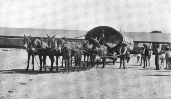
The handling and hauling of the pipe sections, weighing from 7,000 to 12,000 pounds each, a total of about 600 tons, was expeditiously completed as shown by photographs Nos. 63, 64 and 65.
| |||
| Photograph No. 63. Unloading Pipe Sections at Zamora |
| |||
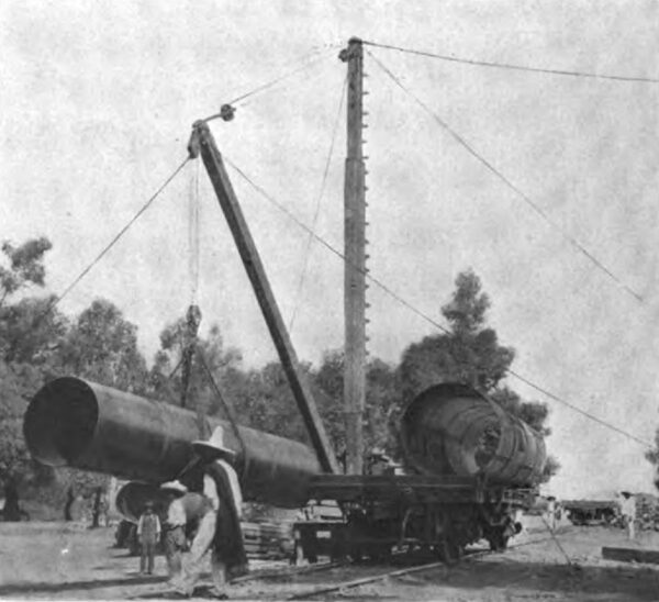
| Photograph No. 64. the Great Oval Taper Section, Ready to Start From the Railway Station at Zamora for the Head of the Pipe Line Near El Platanal |
| |||
| Photograph No. 65. Sections of Pipe Passing Through the City of Zamora Toward El Platanal |
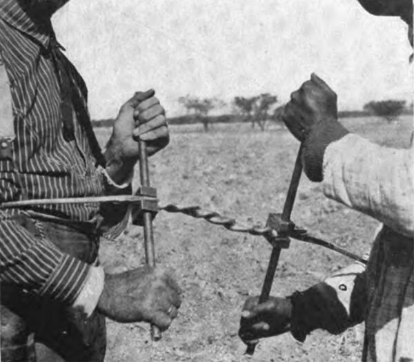
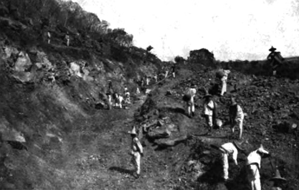
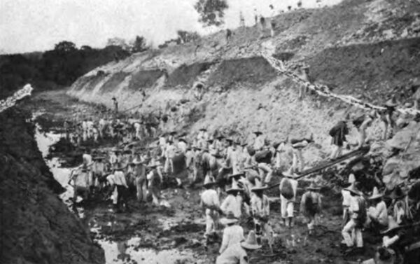
It is to the credit of the transportation organization that all of the hauling was done without the loss of or dam age to a single piece of apparatus. The native methods of excavating the canal and the tail race are shown in photographs Nos. 66 and 67.
Carrying out a project of this magnitude in Mexico is made doubly difficult by the dense ignorance and absolute carelessness of the laboring class. The laborers, or peons, are mostly Indians or half breeds, except where they are specially imported. These people wear as little clothing as possible, eat and drink whatever comes to hand, smoke cigarettes incessantly, are always ready to talk or play and are never ready to work.
From time immemorable they have carried things on their backs and it becomes necessary for the American to adapt himself to their ideas in order to get work done. It is exceedingly difficult, if not impossible, to teach them new methods of working. The customary method of handling dirt is by means of baskets or costals (a small piece of burlap), carried on the back.
| |||
| Photograph No. 66: the Native Method of Excavating the Canal. |
It is reported that when one contractor attempted to introduce the use of wheelbarrows, the peons preferred to carry the barrow, load and all, on their backs rather than learn how to wheel it on a runway.
The wages paid to the laboring man vary from $0.40 to $0.60 per day, Mexican, if he be unskilled, $0.75 to $1.25, if he be a cabo (gang boss), from $2.50 up wards, if he be a skilled artisan, and are unquestionably greater than he knows what to do with. On Saturday night the man whose weeks work has brought him $2.40 in Mexican silver is so wealthy that he makes a bee line for some place where he can spend his money with the least exertion. Saturday night is usually spent in drinking the vile intoxicants, which are very cheap, and in gambling, and there is rarely a Sunday in a large construction camp that is not celebrated by some shooting or stabbing affray. Monday has been christened San Lunes (Saint Monday) because the men are entirely missing or medio crudo (half drunk), and trying to taper off. In addition to Sundays and Mondays there are in each month a few church holidays upon which no good Mexican works.
| |||
| Photograph No. 67: the Native Method of Excavating the Tail Race Canal |
The men bring their wives and families into the camp and set up housekeeping in a one roomed shack, easily constructed in half a day, of boulders, and thatched with weeds. Packing boxes were good enough for some, and one family squatted in a short spare length of steel pipe 69 inches in diameter. Nature is kind to these people, furnishing warmth and food such as it is. The only incentives to work are curiosity and a desire to obtain the means with which to get drink and to gamble.
The short time in which this project was executed is most remarkable and is characteristic of the management. The preliminary examination was made in March and April, 1902, construction was begun in the fall of the same year, and in October, 1903, the plant was put into regular operation.
This, undoubtedly, establishes a record in Mexico for rapid and efficient execution of construction work of a technical character and of considerable magnitude, especially in view of the fact that the work was completed within the estimates of cost.
