[Trade Journal]
Publication: The Journal of Electricity, Power and Gas
San Francisco, CA, United States
vol. 14, no. 8, p. 227-229, col. 1-2
The Remaining Transmission Papers.
Concluding the Transactions of the Monterey Convention of the Pacific Coast Electric Transmission Association, June 21-22, 1904.
A SIXTEEN-MILE, 80,000-VOLT, EXPERIMENTAL LINE.
BY A. C. BALCH.
EARLY in 1903 the discussion arose regarding the proper insulators to be used on the then proposed Kern River transmission line which was to be 125 miles in length, and to deliver at its terminal ten thousand horsepower. The copper had been determined for a working voltage of 45,000 at the power house, and 40,000 at Los Angeles with both lines working. The country about Kern River, however, having great water powers available, it was quickly seen that a higher voltage would be desirable in order to carry more power to Los Angeles over the same line. Accordingly Mr. W. G. Kerckhoff, president of the Pacific Light and Power Company, instructed that a tests should be made of the various types of line insulators then on the market.
| |||
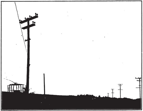
| A Section of the 80,000-Volt Experimental Line |
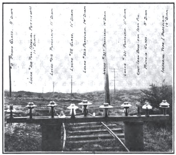
Nine types of insulators were available for testing and each type was installed part with wooden pins and part with metal pins; the cross arms being painted with metallic paint.
For convenience the insulators here are referred to as Porcelain 3-14-29 1/2 ; the first figure being the number of pieces, the second figure the diameter of the largest petticoat, and the third figure the creepage surface, i. e., the actual surface distance between the wire and the pin. Stated in this way the insulators were as follows:
Locke Porcelain 3-14-29 1/2
Locke Porcelain 3-11-28
Locke Porcelain 3-11-27
Locke Porcelain 2-11-25
Locke Porcelain 4-14-35
Locke Glass 2-II-23
Provo Glass 1-9-16
Muncie Glass 1-9-16 1/2
Knowles Imperial Porcelain 1-10-21
Allen Special, composed of 2-story Provo 1-9-16
A single insulator being mounted on top of two others with the cross piece supporting the upper insulator.
On April 1st a line sixteen miles in length having three wires mounted in triangular shape with a distance of 40" between wires was started up. The test continued until June 1st. During this time all sorts of weather was experienced, including heavy fogs and light and heavy rainfalls. In one night 4 of rain fell on the country through which the line was built.
| |||
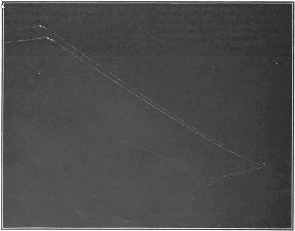
| A Night View of the 80,000-Volt Experimental Line |
The line ran east and west through the San Gabriel Valley, about one mile from the foot of the Sierra Madre range and parallel to the same.
During this test the usual experience of having no difficulty whatever with new insulators was most prominently noted. There was an average of 80,000 volts between two of the wires and the third wire. Only single-phase transformers were available, and these were two 40,000-volt transformers, which were connected in series with the center between the two grounded. Each transformer had a capacity of 250 K. W. Two of the wires were connected to one of the outside terminals of these transformers and one to the other. The current transmitted to the line was measured with a standard ammeter, which was placed in the line wires and set on top of the line insulator. This ammeter showed no apparent tendency to become inoperative on account of static charge. The current to the line was approximately 3 amperes, and this did not vary more than 5% at any time during the test.
The size of the wire was No. 4 B. & S. gauge.
A sharp rattling sound was in evidence, which seemed to be localized at points along the wire varying from one pole length to a half pole length, but could never be placed. It is difficult to determine whether the noise actually shifted or whether it was an error due to the listener. At times it seemed as though objects extending up from the ground, like neighboring trees and poles standing in the line, made greater noise apparent in their locality, but this was not definitely found to be the case. No danger could possibly have come to a lineman by his thinking the current was off when it was on as the Sound could easily have been heard a hundred yards from the line at any time. A native of the locality said that the line sounded like bees, and a great many of them. A reduction of 20% in the voltage practically stopped all the noise.
The line was luminous on a dark night or when looking toward a dark mountain on any night, and presented the appearance of a stream of bluish light about three inches in diameter for each line. This line did not show any nodes or extra brilliant points, but seemed to have exactly the same luminosity throughout its entire length. There was no extra intensity of brilliancy at the insulators or any other place, except at the tie wire on the top of glass insulators it seemed to somewhat enlarge the luminous volume which appeared as a somewhat brighter point than the other portions of the wire. The single wire, however, was considerably brighter than the other two, and could be seen at times and conditions of darkness when the other two wires were not in evidence, although the glass insulators on the other two wires were in evidence.
In extra dry times the luminosity was somewhat greater and was frequently reported to be visible a half mile from the line, and was seen on many occasions as far as a mile from the line. The luminosity was of such a nature as to actually illuminate the surrounding objects, which made very perceptible shadows. A camera set at the power house clearly showed ten spans of the single wire and showed three insulators on each of the poles in question. The telephone insulators on the first two or three poles were also evident in the photograph.
A telephone line ran about six feet below the lower cross arm, and this line was charged so that it would flow one-half ampere through 100 ohms; i. e., it would light a 32 c. p. lamp of half candle power when connected directly between the combined telephone wires and ground. On open circuit, however, either of the telephone wires would discharge a spark 4 inches long to ground terminal. In spite of this, however, the telephone was easily used, provided the operators were willing to chance the conditions of static charge. This was only tested by standing on insulated stools and not used for regular work.
No difficulty was experienced in throwing the current on the line during a fog or in any other weather.
One day after a Locke 2-11-23 was put on the line the outer piece was found to be split vertically through the top groove, but the inner piece held the voltage successfully except for a small amount of arcing, which caused the patrolman to shut the line down the next day and replace the insulator.
On April 18th, a Knowles Imperial Porcelain 1-10-21 broke down and burned the top off the pole, making a short circuit and shutting down the line. This porcelain insulator was split down from the top a little to one side of the center in a manner similar to that shown by the Locke which had previously broken.
On April 29th, a Muncie glass 1-9-16 3/4 broke down, shutting off the test. This insulator also had a vertical crack as though it were split down from the top and parted through the threads letting it drop free from the pin.
On May 21st, a Knowles Imperial Porcelain 1-10-21 was broken off and carried away the top of the pole down as far as the second cross arm; the wires remaining clear until the arms fell, thus bringing the wires into direct contact.
During the entire test three wires on the other side of the poles, spaced with the same 40-inch distance, carried a 3-wire 15,000-volt line which was doing regular business and no difficulty whatever was experienced with it.
| |||
| Types of Insulators Used in 80,000-Volt Line Experiments |
The conclusions arrived at by this test were that all is well while the insulators are new, or during any period when the insulators have no dust which can become mixed with fog or moisture by weather conditions.
No difference was experienced between wood and iron pins and in no case did the current short circuit from the wire to the pins over the insulators.
The results pointed out to the Pacific Light & Power Company were that it would be well enough to use a large insulator. Their general knowledge of porcelain led them to adopt for the Kern River line a brown porcelain and the insulators were made of four pieces. The insulator was not unlike the usual 15-inch Locke insulator, known as No. 329. The only difference between the Kern River insulator and the Locke No. 329 is that the inner petticoats are spread somewhat in order to allow the company to apply what they consider to be the cure for all evils. This cure, which was to keep the insulators in as good condition as new for an indefinite length of time was to have the lineman climb the pole once or twice a year, varying with the local conditions, and wipe out the inside of the insulator thoroughly with a cloth in order to remove the dust which might be collected there, at the same time inspecting the pole top carefully. This, it is believed, will keep the insulators as good as new, and if they are so kept the company feels safe in assuming that 66,000 volts will cause them no difficulty whatever.
*A paper presented to the Eighth Annual Convention of the Pacific Coast Electric Transmission Association, Monterey, California, June 21-22, 1904.
