[Trade Journal]
Publication: The Journal of Electricity, Power and Gas
San Francisco, CA, United States
vol. 14, no. 2, p. 77-89, col. 1-2
The American River Electric Company's Plant on the South Fork of the American River.
[Five years ago the construction of a transmission line of the magnitude of the American River Electric Company would have called forth columns of comment and description from every editorial writer on the Pacific Coast. Special reporters would have been assigned to obtain a good write-up, with illustrations of the plant, and portraits of the capitalists and engineers interested in the work.
Whether it is that Californians are becoming used to the idea of long distance transmission, owing to the many magnificent plants already in operation, or whether the builders of the American River Companys plant were too modest to exploit their enterprise, or whether notices of electrical progress have become a drug in the columns of the daily press, the fact remains that a large plant has sprung up almost in a night, in a thickly settled portion of central California, without its existence being heralded or even known through the usual mediums of current happenings.
| |||
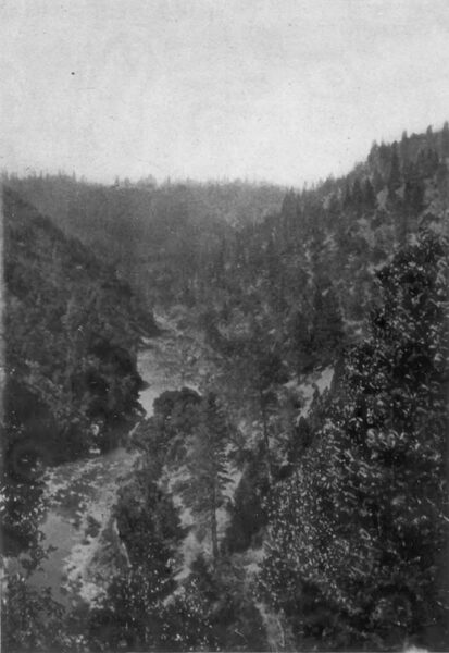
| Scene on the American River. Source of Water Supply of the American River Electric Company |
A few local capitalists, through the enterprise of an engineer, had pointed out to them the possibilities of a rare location they knew a good thing when they saw it, and without any promoting or seeking outside assistance banded together, subscribed the necessary capital and with characteristic zeal put through their project on what is record time, and are now enjoying the fruits of their sagacity and labor. The work of construction was begun July I, 1903, and the plant was in regular operation on December 31st of the same year, despite the fact that roads had to be built in a rough and mountainous country, bridges constructed and many difficulties in the way of engineering work encountered. Notwithstanding what may be termed its hasty building, the plant stands today as a model transmission line among the many of the Pacific Slope.THE EDITOR.]
IN April, 1903, after all the preliminary data had been ] secured, the American River Electric Company was incorporated with the following board of directors: Mortimer Fleishhacker, Herbert Fleishhacker, Lieutenant-Governor Alden Anderson, W. E. Gerber, Frank Buck, Henry Kahn and W. A. Bell. The officers elected were Mortimer Fleishhacker president and Herbert Fleishhacker secretary. The plans laid out were for a 3000- kilowatt plant, with provisions for extensions covering a distributing pole line of 110 miles.
Contracts were let and active work inaugurated on July 1, 1903.
The power house is located on the South Fork of the American River, four miles north of Placerville, El Dorado County. From this point power is transmitted to Stockton, a distance of eighty miles, and also to Folsom, thirty miles distant, both of these points being served by separate lines direct from the power house.
The longer line passes through the towns of El Dorado, Plymouth, Amador City, Sutter Creek, Jackson, Valley Springs and into Stockton; the shorter branch through Diamond Springs and Shingle Springs before reaching Folsom.
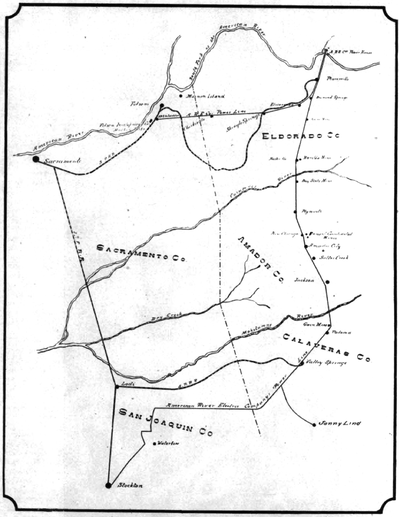 |
| Map Showing Pole Line of the American River Electric Company's System |
Placerville is fed by a separate 2200-volt circuit, direct from the generators, the other lines being built with the ultimate intention of operating at a potential of 60,000 volts.
The dam is situated approximately seven miles above the power house, and on account of the roughness of the country the first four and one-half miles leading from it is nearly all flume, broken occasionally with a short stretch of ditch. The remainder of the waterway is entirely good ditching.
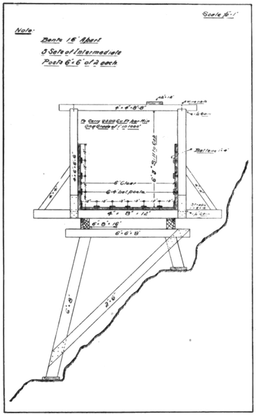 |
| Flume Detail of the American River Electric Company's System |
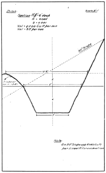 |
| Ditch Detail of the American River Electric Company's System |
The flume is six feet in width and at present is planked four feet on the sides, provision being made for increasing to six-foot sides when the growth of the plant warrants, which will give the flume a capacity of about 9500 cubic feet per minute. The grade is one foot in a thou sand, the flow of water being smooth and even, owing to the bottom and sides of the flume, as well as the battens, being surfaced lumber. The accompanying drawings of flume and ditch show the flume and ditch construction. From the fact that the waterway lies on the north bank of the river, exposed constantly to the sun, no danger of freezing in the winter months is anticipated. Spill gates are provided at intervals to turn the water out when needed.
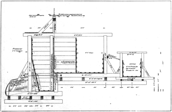 |
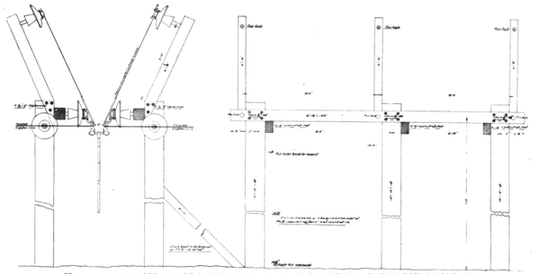
| Sectional View of Penstock of the American River Electric CampanyS System |
Should it become necessary to make repairs or changes in the upper portion of the flume, water can be used from two creeks flowing into the ditch some two miles from the power house, which in winter develop a sufficient volume to run the entire plant. In addition to the supply furnished from above the dam, and these small streams, storage reservoir sites have been secured in close proximity to the waterway capable of impounding a vast amount of water, so that the source of power may be always relied on.
The penstock is of timber construction, provided with sluicing gates and a spillway of sufficient capacity to take care of all the water in case of a shut-down.
Extending the whole length of the penstock is a double screen, made of half-inch, square-mesh, galvanized iron wire, which is stretched over small iron frames. These frames are adjusted in such a manner that any section may be conveniently moved and cleaned, and also that none of the pipes is dependent on any one portion of the screen for water, so that an insufficiency of water, through the choking of the screen, is an eliminated element.
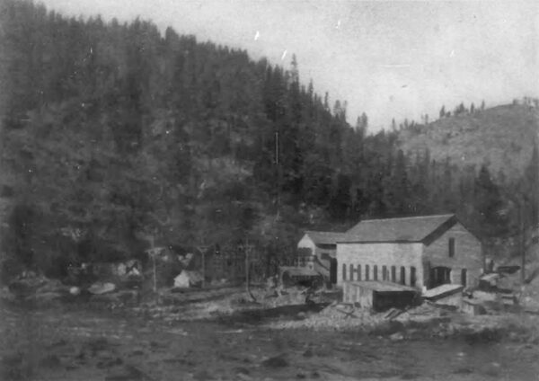
| |||
| American River Electric Company's Power House in Course of Construction |
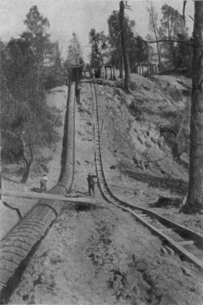
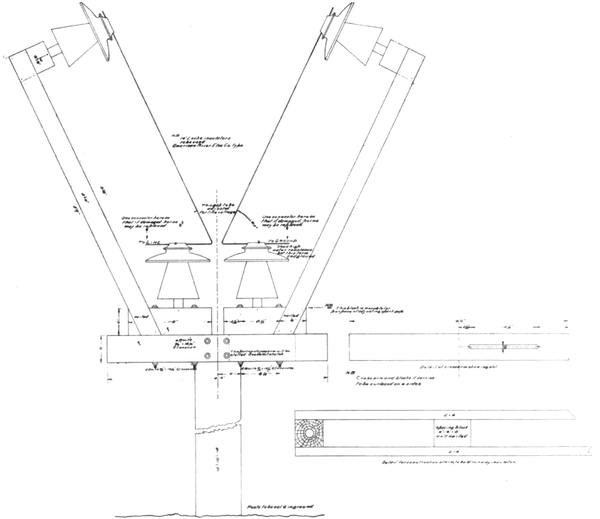
While at present there are but two pipe lines leading from the penstock, provision has been made for the addition of another should it become desirable or necessary. From specially constructed boxes attached to the penstock two pipe lines extend to the power house, each being thirty-six inches in diameter throughout. The upper 400 feet of these lines is of redwood stave. with a maxi mum head of 120 feet, the rest being of varying thick nesses of riveted sheet steel. The maximum static head from the penstock water level to the center of nozzles is 575 feet.
Each line branches at the bottom just outside the power house, forming a Y, the branches leading to the nozzles of two Pelton water wheels carried on the ends of the generator shaft.
The power house is constructed of concrete, with steel trusses and a slate roof, making it thoroughly fireproof, and incidentally providing a cool place during the hot summer mouths. Running the entire length of the building is a hand-operated, twenty-ton crane. Two Westinghouse three-phase, 1500-kilowatt, sixty-cycle, 2200-volt, engine-type generators furnish the power, the sub-base bearings and shafts forming a part of the water-wheel construction. The shaft is of forged nickel steel and has a five-inch hole bored through the center from end to end. Each generator is driven by a double water-wheel unit, each unit being provided with a type Q Lombard governor for operating the two nozzles through a rock shaft.
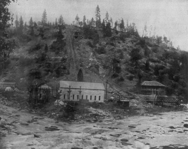
| |||
| Power House of the American River Electric Company |
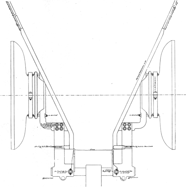
The wheels are constructed of cast-steel runners fitted with cast-iron Pelton buckets, the maximum output of each double unit being 3000 horsepower. The wheels are equipped with combination deflecting and needle regulating nozzles of Pelton design and construction.
The two bearings of the generator shaft are of the ring oiling, generator type, the shells carrying the oil and being provided with water-cooling compartments. Inside of the wheel housings the water for circulating is caught in a trough of sufficient elevation to flow through the compartments to keep the oil cool. Water is also led into the ends of the hollow shaft through a one-inch pipe, which discharges it at the bearing portions of the shaft.
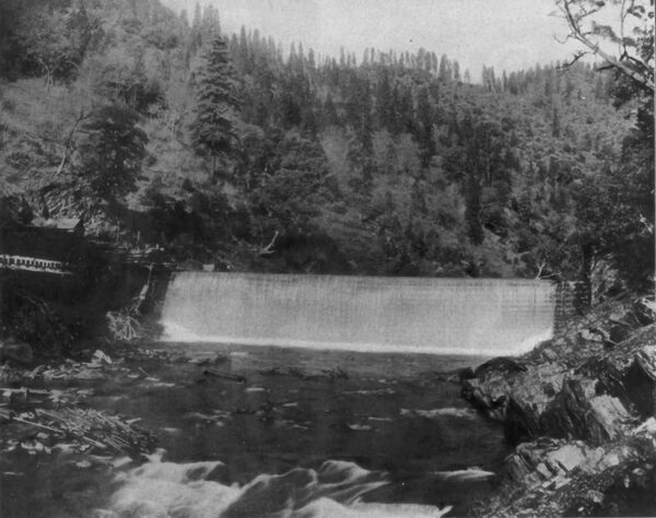
| |||
| Dam of the American River Electric Company |
In addition to the generating units above mentioned, there are two exciter sets, each consisting of a seventy five-kilowatt, 125-volt, 750 revolutions per minute, Westinghouse, multi- polar, direct-current generator, driven by a twenty-eight-inch Pelton wheel, either set being of sufficient capacity to excite the main units. The water for the exciter wheels is taken from the main lines just outside of the building, the arrangement being such that each set may be driven from either pipe line. A type F Lombard governor is set between the exciter wheels, so situated as to control either unit.
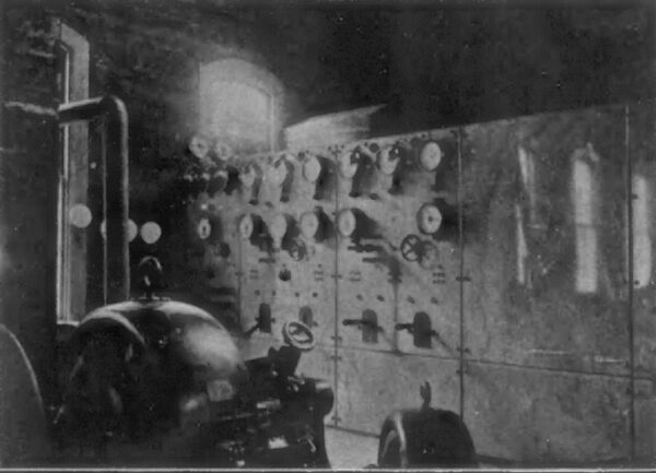
The switchboard consists of seven panels of bevel-edged Vermont blue marble ninety inches high, mounted on an angle-iron framework. The panels are designated as follows: A, exciter; B and C, generator; D, blank; E and F, transformer, and G, Placerville circuit. On the exciter panel are mounted one 150-volt, direct-current, type D voltmeter, two 1000-ampere, direct-current, type D ammeters, one five-ampere, alternating-current, type F ammeter (the last named being used in connection with a water signal for the pen stock), two 800-ampere, three pole, double-throw, quick-break switches, two field rheostats, pilot lamps and plugs.
| |||
| Penstock and Pipe Line of the American River Electric Company |
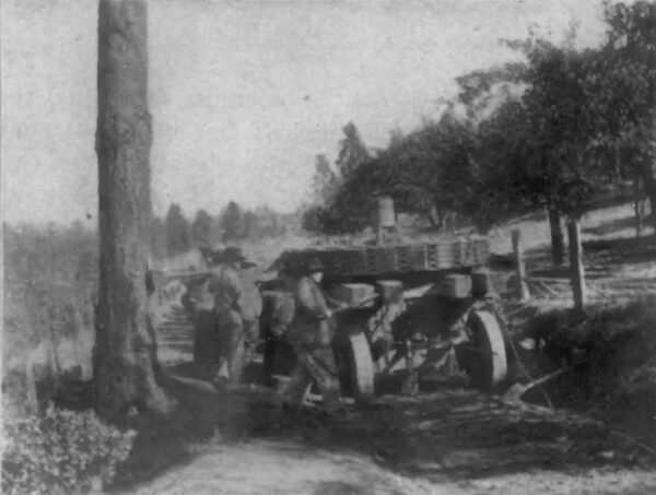
| |||
| How the Machinery Was Transported |
| |||
| The Switchboard at the American River Electric Company's Power House |
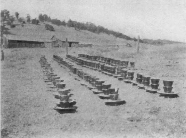
| |||
| A Field of Locke Insulators |
Panels B and C, for controlling the two 1500-kilowatt, 2200-volt, three-phase machines, have three indicating recording ammeters. one indicating Bristol recording voltmeter, one frequency indicator one power-factor indicator, two 600-ampere, single-pole, oil break switches, one double throw, two-pole, field switch, with resistance, one rheostat mounting, pilot and synchronizing lamps and voltmeter plugs.
Panel D will be used for con trolling the third main unit when installed, and will resemble in all respects panels Band C. On each transformer panel is mounted one 800-ampere, alternating-current type ammeter, two 600-ampere, 2200-volt, three-pole, single-throw, type B, interlocking circuit breakers.
On panel G is one triple-pole, double-throw oil switch, one Bristol recording voltmeter and three Bristol recording ammeters and fuses.
One interesting feature of the switchboard is a swinging arm, on which is mounted a synchroscope and indicating voltmeter, so connected that by means of plugs they can be thrown on any of the circuits desired.
Another feature is an electric attachment to control the governors of the main units, allowing the attendant to manipulate them from the switchboard.
| |||
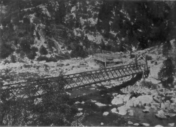
| Bridge 232-Foot Span, American River Electric Company |
The ammeter on panel A, which is used in connection with the water signal, is in series with a solenoid at the penstock, on a 110-volt, alternating-current circuit. An iron core controlled by a ball float in the penstock moves in and out of the solenoid, thus changing the amount of current in circuit, which is shown on the am meter. The solenoid is wound so that the current change is almost a straight line, enabling the attendant to determine the exact position of the water in the pen stock.
All generator leads are carried to the switchboard, under the floor of the power house, in six-inch glazed sewer tiling, and the wires for lighting purposes in flexible iron conduits imbedded in the walls. The lead wires are rubber-covered, double-braid cable of 250,000 circular mils and run in pairs from the generators to the switchboard.
In a separate building, the materials of which are identical in construction with the power house and twenty-five feet distant therefrom, are located the step up transformers. These are seven in number, six being in active service, the other held as a spare.
| |||
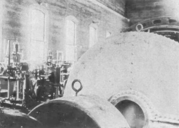
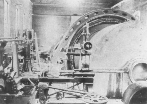
| Pelton Water Wheel in American River Electric Company's Power House |
| |||
| One of the 1500-Kilowatt Generators |
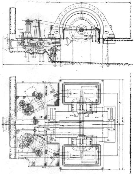 |
| Diagram Showing Pelton Water Wheels in the Power House of the American River Electric Company |
The transformers are of 625 kilowatts capacity each, oil insulated, water cooled, and designed to be connected for star in line voltages of 60,000, 50,000, 40,000 or 30,000 volts, and in delta for the generator side. The regulation at 100 per cent. power factor is 1.75 per cent., and they will operate continually at full load with a rise in temperature not exceeding 40 degrees above the surrounding atmosphere. The transformers are mounted separately on steel trucks with cast-iron wheels, allowing them to be readily moved about. Each requires two and one-half gallons of water per minute for cooling purposes.
Every precaution has been taken in the transformer house against damage resulting from fire. In addition to a three-inch wrought-iron pipe leading from each transformer case to the outside of the building, allowing for the running off of the oil, an ingenious automatic device has been attached to the outlet pipe which eliminates attention from any other source. It consists of a small drum ten inches in diameter, with a three-inch face, fastened to the valve stem, around which is wound twelve turns of flexible wire cord. This cord on leaving the drum passes over a system of small iron pulleys to the outside of the building, and has attached to the end of it an iron weight, held up so as to have a drop of two feet by a hemp cord, which passes into the building and just over the top of the transformer case. In the event of fire the cord is burned through, releasing the weight, which in descending will unwind the drum, thereby opening the valve full, allowing the oil to run off through the pipe to the outside.
The low-tension leads are carried underground in six-inch glazed sewer tiles, while the six-inch high-tension wires leave through twenty-four-inch conduits of the same material set in the end wall of the building. Inside, the high-tension leads are carried on fourteen inch Locke insulators, supported on six-by-eight-inch beams running across the building above the transformers, connections being made with transformer leads by taps.
 |
| Framework and Assembly of Switch at Power House of American River Electric Company |
 |
| Lightning Arrester at the American River Electric Company's Power House |
 |
| Assembly Drawing of High Tension Switch at American River Electric Company's Power House |
Outside the building are located the high-tension switches and lightning arresters, the latter being of the horn type, and mounted so that they may be easily adjusted for any desired voltage by loosening two nuts and moving the horn support on the grounded side. The pulled apart and the ends so fastened that there is about one-quarter-inch air space between each turn of coil.
The high-tension switches are of a fused type. The two knife edges are connected by means of a glass rod, and the two points fused, the fuse being held beneath a winged net.
The parts of the switch are few and simple, the arrangement of which may readily be seen from the accompanying diagram. The triangular-shaped part which carries the brass clips is fastened to a standard fourteen-inch Locke insulator by means of a screw and stud securing it to a clamp surrounding the neck of the insulator. The leads are sweated into the ends of the brass runways at the bottom, When the switch is pulled, or the fuse blows, the magnetic field is below the arc, thus not interfering with the tendency of the arc to travel upwards.
Great care has been taken to protect the attendant while operating the switch. An insulated handle is provided six feet in length, on the upper end of which is a brass socket, which makes connection with an attachment on the glass rod supporting the knife edges by means of a bayonet joint. Between the socket and the handle-grasp is four and one-half feet of one-and-one half-inch round maple, treated with a weather-proof varnish, the handle-grasp being made up of a piece of heavy glass tubing, one and one-half inches outside diameter, slipped over a projection of the wooden portion and firmly glued. The glass is covered by a section of the best quality rubber hose, the ends being securely sealed with an insulating compound.
To guard against the attendant coming in contact with the insulated portion of the handle, a shield is provided at the upper end of the handle-grasp. This consists of a circular piece of plate glass four and one-quarter inches in diameter, with a one-and-three-eighths-inch hole drilled in the center, which is slipped over the pole, and protected from breakage by a fiber washer of rather larger dimensions inserted behind it, the glass being next the hand. As a further precaution the upper portion of the handle is grounded by means of a brass chain. The switch is operated by the attendant from a platform built upon six fourteen-inch Locke insulators, affording further immunity from accident.
As usual in most of Californias hydraulic transmission plants, it was necessary to construct a road to the power house of the American River Company, but in this case a bridge was required to span one of the streams encountered. That the bridge forms not only a useful, but an ornamental part of the road as well, can be seen from the engraving. The bridge is of the suspension type, supported by two plow-steel cables two and one-half inches in diameter. From these is hung the floor, on either side of which is a stiffening truss with eight-by-eight-foot panels. The span from bank to bank is 232 feet.
The transmission line is double, each one carrying three phase circuits of No. 1 B. & S. gauge seven-strand bare aluminum wir2, weighing approximately 401 pounds per mile, the lines being twenty-five-foot centers. The poles are well seasoned round cedar, set 180 feet apart, the butts for protection being thoroughly treated to a coating of Carbolineum Avenarius.
The dimensions of the cross-arms are four and three-quarter by five and three-quarter inches by seven feet. Two wires are carried on fourteen-inch Locke insulators attached to these, with pin holes six-foot centers. The third wire is fastened to the tops of the poles. Pins for cross-arms are seventeen and one-half inches in length and for the tops of the poles nineteen and one-half inches. To keep the poles from splitting the tops are wound with eight turns of No. 10 galvanized iron wire. Each pin is protected from leakage discharge by the entire length of its shaft being wrapped in sheet zinc, the extra cost for which is less than $0.03 cents per pin.
The Placerville wire is carried from the power house to that point on cross-beams six by eight inches, spanning opposite poles, as is also the telephone line. From Placerville to other points the telephone wire runs on separate cross-arms set below the transmission lines.
Two substantial substations have been erected, one at Folsom, constructed of corrugated iron and covered with P. & B. roofing, the other of brick at Stockton. Both of these substations are equipped with high-tension switches and lightning arresters with choke coils, similar in all respects to those installed outside the main power house. Aside from the revenue derived from commercial sources, the company at present is enjoying very substantial returns from the power supplied numerous mines situated adjacent to the pole lines, and looks forward to a further income from furnishing power for pumping purposes to develop the rich low lands tributary to it. Abundance of water can be had in these localities at a depth of twenty feet and, with cheap power at hand, the agricultural interests of this section of the country will receive a fresh impetus.
The design and construction of this plant, from beginning to completion, the work of A. M. Hunt, of the Engineering Offices at San Francisco, and it was due to his skill, knowledge, energy and fore sight that the many engineering difficulties were overcome and the plant completed and put in operation in such a marvelously quick time. Mr. Hunt achieved a national reputation when he installed the plant of the Independent Electric Light and Power Company, this plant being recognized as the best and most up-to-date of its kind in the United States. The absorption of this company by the San Francisco Gas and Electric Company and the resignation of Mr. Hunt as general manager, leaves him free to devote his time to the development of other work. In building the American River plant he was ably assisted by B. C. Condit, superintendent of the company.
 |
