[Trade Journal]
Publication: Engineering News
New York, NY, United States
vol. 48, no. 15, p. 282-285, col. 1-3
THE AURORA, ELGIN & CHICAGO THIRD-RAIL ELECTRIC INTERURBAN RAILWAY.
Among the numerous interurban electric rail ways now in operation or under construction, one of the most important and most interesting is the Aurora, Elgin & Chicago Ry. , which has recently been completed, and which was opened for traffic on Aug. 25. The line is designed for high-speed service, has a double track for a large portion of its length, and is operated entirely on the third-rail system. This system was adopted as being an improvement upon the trolley system for railways of this class, being better adapted for high-speed service, and more economical in maintenance than the ordinary overhead construction.
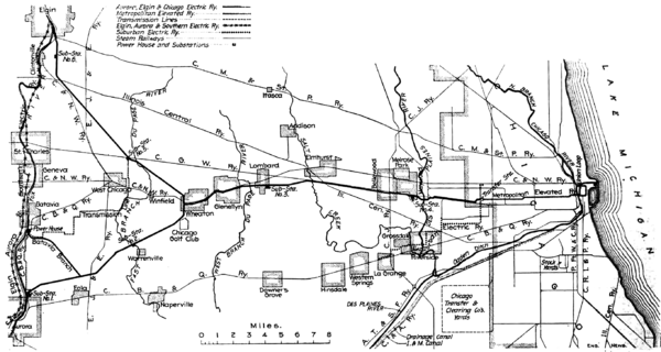 |
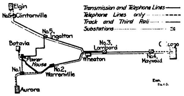
| Fig. 1. Map of the Aurora, Elgin & Chicago Ry. Co.'s Third-Rail Electric Interurban Ry. Charles Jones, Chief Engineer, Wheaton, III. |
As railways of this class have developed from the electric street railway there is still a general tendency to speak of them as street railways, even when built upon private right of way a matter of fact, they may be fairly considered as forming a special class of themselves, and the line in question conforms very closely to ordinary steam railway practice in its location and construction. The railway is built entirely upon its own right of way, and its construction has involved some heavy cuts and embankments to give the easy grades and curves demanded by a high-speed line. It is of substantial construction, with steel and concrete structures throughout and a heavy track.
The road will have about 82 miles of main line, of which 21½ miles are double track. The distance from Chicago (52d Ave. and Harrison St. ) to Wheaton and Aurora is 33.3 miles; the line from Wheaton to Elgin, 16.5 miles ; and the Batavia branch, 6 miles. It will serve a population of about 80,000 outside of Chicago. The same interests own the Elgin, Aurora & Southern Traction Co., with 70 miles of track. Of this length, 37 miles comprise the interurban line between Carpentersville and Yorkville, while the balance consists of city or street lines in Aurora and El gin. Fig. 1 is a map of the railway.
The line will be operated mainly by trains instead of single cars, the multiple unit system being adopted, in which each car has its own motive power, but all the motors are controlled from the head of the train. There will also be trail cars without motors, to be attached to motor cars for two-car trains.
There are trains in both directions every half hour. At present the time allowed for the run between Aurora and Chicago or Elgin and Chicago is 1 hr. 15 mins., but this will be reduced to 45 minutes as soon as everything is in good running order. This will give an average speed of about 45 miles an hour from start to finish, which will necessitate actual running speeds of 50 to 60 miles per hour. The traffic is handled by the telephone train dispatching system, the head dispatcher at Wheaton communicating with the men at the substations, or with the conductors, who report at these stations. The cars are equipped with portable telephones, and means for connecting these with the telephone wires are provided in small iron cabins at all turnouts and cross overs; while at intervals along the road the wires are brought down the poles so that the telephones can be attached. Block signals may be introduced later.
ROADWAY AND TRACK.
The width of right of way is mainly 66 and 100 ft. The lighter grading was done with plows and scrapers, while the heavier work was done with steam shovels and locomotives and side dump cars, temporary trestles being used for building the center of the large banks, which were then widened out as required. Narrow-gage construction tracks were used at some points, and standard-gage tracks at other points. Along the Fox River, on the Elgin line, the bank is built in the shallow water along the east shore. On single-track portions of the line the cuts are excavated to a width sufficient for double track. The maxi mum grade is one of 1.8 %, a mile in length, entering the Fox River valley, but on the rest of the system the aim has been to limit all grades to 1 %. The ordinary curves connecting long tan gents are of 1° and 2°, and the maximum on high speed portions of the line is 4°. Near the Chicago terminal two reverse curves of 16' (with a short tangent between) are required to avoid interference with cemetery property, but as these are between two railway grade crossings (at which all cars must stop) they do not affect the question of speed. The superelevation on curves is about 1 in, per degree, with a maximum elevation of 5 ins.
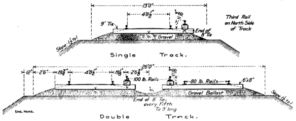 |
| Fig. 2. Cross-Sections of Roadbed and Track of Third-Rail Electric Railway. |
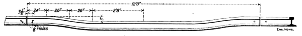 |
| Fig. 3. Drop Rail at Switches. |
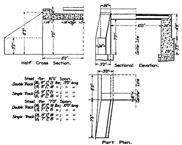
The width of roadbed is 16 ft. for single track (13 ft. over toe of ballast), and 28 ft. for double track (26 ft. over ballast) , as shown in Fig. 2. The track is laid with 80-lb. rails of the Am. Soc. C. E. section, 60 ft. in length, and having about 0.6 % of carbon. They are laid with broken joints and spliced with angle bars and four 1-in. bolts with lock nuts. Bolts of this size are rarely used on steam railway track, except for frogs. In tracklaying, the 60-ft. rails are unloaded from the cars by hand, being run out over two timber horses or "dollies" placed on the subgrade, ahead of the car. The first of these is a little lower than the floor of the car, and the second is considerably lower, and each has at the top an iron roller. On double track, the tracks are 13 ft. c. to c., and are connected by crossovers at intervals of three or four miles. On single track there are passing sidings at similar intervals; these sidings are 700 ft. to a mile in length, long sidings being provided at curves so as to provide practically double track, and thus give greater safety for high-speed running at some points. There are 32 oak and cedar ties to a 60-ft. rail, and the ballast is of gravel, with a depth of 9 ins. under the ties. The rail joints are fitted with the electric bonds of the Protected Rail Co. , of Philadelphia, Pa. , or with the 12-in. "United States" rail bond of the American Steel & Wire Co. , of Chicago. The rails are cross-bonded at intervals of 500 ft. The switches are of the split pattern. with 15-ft. reinforced switch rails; and No. 10 spring-rail frogs are used for main track turn outs. High switchstands are used, except in yards. The switch and crossing work was built by the Morden Frog & Crossing Works and the Ajax Forge Co., both of Chicago.
The conductor or third rail is of the 100-lb. Am. Soc. C. E. section, in 33-ft. lengths, and is of much softer steel than the track rails, having only about 0.1 % carbon. The object of this is to give greater conductivity, but as the softer steel rusts and corrodes much more quickly than the harder steel, the third rail is painted with a cheap asphalt paint thinned with gasoline. This rail is carried by insulating supports on the ties (every fifth tie being of extra length), as shown in Fig. 2. These supports are blocks of wood boiled in paraffine. The joints of the third rail are spliced with two-bolt malleable cast-iron splice bars, and are fitted with the Protected Rail Co.'s rail bonds of U-shape. The holes in the rail flanges for attaching the bonds were made after the rails were laid; some were punched by a port able hydraulic press, and others were drilled (either by hand or by a gasoline machine mounted on a hand-car). At grade crossings, the third rail is cut; the last rail is dropped 2 ins. in its length and has its end fitted with an incline 24 ins. long to raise the contact-shoes of the cars into place. At switches a "drop rail" is used, as shown in Fig. 3, so as to clear the shoes of cars on the turnout, the sides of which would otherwise strike the side of the rail. The ends of the rails are connected by cables laid under the crossings. Single cars will drift over the crossings, but trains (and even single cars at short crossings) will have the front shoe again in contact before the rear shoe has left the rail.
All highway grade crossings are planked and fitted with cattle-guards of vitrified clay blocks, made by the Climax Stock Guard Co. , of Chicago, and bell or other warning signals may be installed later at important highways. There are only four railway grade crossings, one of which is a crossing of an electric line operated by only one car per hour. The other three (one of which comprises three parallel steam roads) are protected by interlocking plants.
BRIDGES
All steel bridges were designed in accordance with Cooper's specifications, with his Class E-40 loading. Mr. W. M. Hughes, M. Am. Soc. C. E., of Chicago, was Consulting Engineer for the bridge work, and all these structures were built by the King Bridge Co., of Cleveland, O. There is only one truss bridge, crossing the Chicago & Northwestern Ry. , at Elgin, on a skew. This has a span of 158 ft. 7 ins., with shallow floor construction, and one end rests on columns, connecting with a steel viaduct 363 ft. long.
| |||
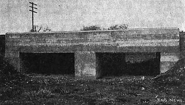
| Fig. 6. Cattle-Pass With Double Opening. |
All the other steel bridges are of plate girder construction. There are two 100-ft. spans (arranged for three tracks) over the Des Plaines River, and a double-track deck bridge of 70 ft. span over the East branch of the Du Page River. At Warrenville there is an 89-ft. span over the West branch of the Du Page River with a 24-ft. cattle-pass and culvert at one end. Besides the Chicago & Northwestern Ry., already noted, the line passes over two other railways, by girder spans of 69 and 80 ft., respectively. It also passes under five railways, which are carried by girder spans of 36 to 60 ft. There are 12 plate-girder bridges carrying the line over streets and roads, and four carrying roads over the railway. The latter have 45-ft. main spans (to allow for future double tracking), with 20-ft. I-beam approach spans. Besides these there are a number of small openings spanned by I-beams with concrete filling. The steel bridges have open floors, but with closely-spaced ties and a substantial floor system. All piers and abutments are of concrete.
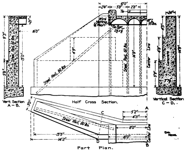
There are four concrete bridges, besides a number of concrete culverts and cattle-passes. The Salt Creek bridge, Fig. 4, has two 35-ft. arches (with a rise of 1 in 6); the Poplar Creek bridge at Elgin has one 30-ft. arch, and another bridge over the West branch of the Du Page River, and on the Elgin branch, has two 30-ft. arches (with a rise of 1 in 10). The smaller structures have arches of 10, 12 and 15-ft. span, and one of these has two 15-ft. spans. Old 60-lb. rails are laid in all the arches, except those of 12 and 15-ft. span. They are placed about 36 ins. apart, near the center line of the arch ring, and extend into the haunches. The standard cattle-pass, Fig. 5, is 10 ft. wide and 7 ft. high, with 10-in. I-beams 14 ins. c. to c., embedded in concrete. One of these, with two openings, is shown in Fig. 6. The beams are embedded in concrete, but are figured to carry the entire load unaided by the concrete. This beam construction enables much lighter abutment walls to be used than for an arch culvert, as there is no thrust to be resisted. The cost is also about 20% less than for an open-floor bridge with I-beams on concrete abutments, since the latter would require heavier abutments than where the beams are embedded in the concrete.
 |
| Fig. 5. Standard Cattle-Pass |
 |
| Fig. 7. Concrete-Steel Bridge With Concrete Jack-Arch Floor. |
In one cattle-pass, Fig. 7, concrete jack arches are turned between the I-beams, but instead of the ordinary removable wooden centering, arches of wire netting were fitted on the lower flanges and the concrete placed on these, being filled in from both sides towards the crown. The end of each I-beam rests on a vertical 60-lb. rail embedded in the abutment, and a diagonal rail is embedded in each wing wall. This arrangement enables lighter walls to be used, with an economy in concrete, and a saving of about 30% in cost as compared with a structure having concrete abutments and an open I-beam floor. All concrete work is made with Portland cement supplied by the Wabash Portland Cement Co., of Detroit, Mich., with works at Stroh, Ind.
STATIONS AND BUILDINGS.
The Chicago terminal is a transfer station for connection with the Garfield Park line of the Metropolitan West Side Elevated Ry., as described in our issue of Aug. 14. The cars run between two platforms, on the outer sides of which is the terminal loop of the elevated railway, which is reached by an incline from the elevated station at 48th St., as described in our issue of July 31. At Elgin and at Batavia the line runs on its own right of way up the river bank to a terminal station in the center of the town. At Aurora the cars run for about half a mile along a street, but the tracks are adjacent to the right of way of the Chicago, Burlington & Quincy Ry. There are about 30 stopping places in all, most of these having simply open platforms at road crossings. Each of the six brick substation buildings has a waiting room and platform for passengers, and there are a few small frame stations. The main repair shops and car sheds are being built at Wheaton, and are of fireproof construction throughout.
CAR EQUIPMENT.
The road has about 30 cars, and others will be added as the traffic requires. Those now in use were built by the Niles Car & Mfg. Co. , of Niles, O. , and were all run to Chicago on their own wheels. One of these is shown in Fig. 8, which also shows the track and third rail. They are 47 ft. 3 ins. long overall, 8 ft. 8 ins. wide, and weigh 74,000 lbs. empty. They are of substantial construction, with steel underframes stiffened by truss rods, and steel-framed trucks. The wheels are 36 ins. diameter, and the axles 62 ins. diameter, with journals 5 x 9 ins.; the axles, boxes, etc., conform to the M. C. B. standards. There is a motor of 125 HP. on each axle, and nearly all the cars are thus equipped, the line being operated mainly by trains of three to five cars ; the electrical equipment is on the multiple-unit system, in which all the motors are controlled from the controller on the front car. There will, however, be some trail cars without motors. Contact shoes are fitted on both sides of each truck, and there are two trolley poles on the roof for use on the short piece of street line in Aurora. The cars have transverse seats, upholstered in rattan, and have seating accommodation for 56 passengers. They are equipped with telephones, Christensen air brakes, electric heaters and electric interior lights and headlights. At one end is a smoking room. The platforms are vestibuled and have side and end doors in the vestibule, the latter al lowing for access between the cars when coupled up in trains. Hinged sections of the floor cover the steps when the doors are closed, and when the car reaches the 52d Ave. transfer station (which has a high platform). The dimensions of the cars correspond very closely with those of the cars on the Chicago elevated railways, and the trucks are so arranged as to enable the cars to readily pass the 90-ft. curves on these lines. This is in view of the possibility of eventually running the cars over the elevated railways into the city.
POWER PLANT.
The current for operating the entire line is generated at one power house, at Batavia, Ill.; this will also supply current for the line from Elgin to Aurora, and for the street cars in these cities. This will not only give greater economy than the present small power stations on these older lines, but the city traffic will tend to equalize the load on the power station and prevent the high peaks which occur when only interurban traffic is operated. The power house is 202 x 160 ft. , of steel frame construction, with a simple but handsome exterior of limestone and common pale brick, and a roof of tar and gravel composition on plank sheathing. The concrete foundations and the masonry were built by the company, while the steel work was built and erected by the Variety Iron Works, of Cleveland, O.
There are three Corliss cross-compound condensing engines of 2,200 HP., built by the C. & G. Cooper Co., of Mount Vernon, O. These have cylinders 32 x 60 and 64 x 60 ins. , with a piston speed of 750 ft. per minute at the normal speed of 75 revolutions The receiver is in the basement, and contains a heater coil. On the shaft of each engine, between the cranks, are mounted a revolving field General Electric generator of 1,500 KW. and a 20-ft. 80-ton flywheel. Space is provided for a fourth engine and generator. There are also two horizontal engines of 200 HP., built by the Phoenix Iron Works, of Meadville, Pa.; each of these drives an exciter of 160 KW. The lubrication is effected by the Siegrist pressure circulating system, the pumps of which are arranged in duplicate for three independent sets of circulating pipes for engine oil, high-pressure cylinder oil, and low-pressure cylinder oil. The oil room in the basement has two tanks for each of these oils, so that one can be filled while the other is in service; in this room also are two Cross filters for the waste oil, made by the Burt Mfg. Co., of Akron, O.
All piping is exposed and within view, instead of being concealed in tunnels or a basement. The main lines of pipe are carried horizontally along the wall of the engine room, the valves being made accessible by an iron L-shaped ladder which travels along the whole length of the wall. With this arrangement all the principal pipe connections, valves, etc., are in full view of the men in the engine room. This room is served by a 50-ton electric traveling crane built by Alfred Box & Co., of Philadelphia, Pa. , and a railway track enters one end of the room so that material can be handled directly from the cars by the crane.
Steam is supplied by eight water-tube boilers of 500 HP. , built by the Edge Moor Iron Co., of Wilmington, Del. , and space is provided for two more boilers. The boilers carry a pressure of 180 lbs. They are fitted with superheater tubes, and have the traveling chain grate of the McKenzie Furnace Co., of Chicago, driven from eccentrics on a shaft placed beneath the floor. The plant also includes Green economizers and Worthington condensers and pumps, the main circulating and feed pumps being driven by induction motors. The power station is close to the Fox River, and the water supply for the boilers and condensers is taken from the river by a conduit which passes through the building, while the waste water is discharged into a culvert which leads back to the river. At the intake is a screen house, with two intake chambers, each fitted with three wire screens, which can be raised by means of a trolley hoist running on the I-beams of the roof. To prevent trouble from ice at the intake, an 18-in. cast-iron pipe is run to it from the condensing plant so that some of the warm water from the condensers can be discharged at the intake instead of into the culvert. The 240-ft. chimney, of brick and stone, is placed at the middle of the building, and the top of its 11-ft. flue is 225 ft. above the grates.
The coal-handling plant is of rather novel design, no continuous conveyor being used. The coal is dumped or shoveled from railway cars into a masonry storage bin parallel with the boiler room, and divided into 18 pockets, each of which has a capacity of 3,771 cu. ft. , the total storage capacity being about 2,000 tons. The bot tom of each pocket has two steel hoppers, the two rows of hoppers being separated by a stone wall pierced with archways. Under each row is a track of 21 ins. gage, the rails being embedded in the concrete floor of the basement (below the boiler room floor), and arranged for outside-flanged wheels, so that the concrete between the rails is made flush with the rail heads and the floor is easily kept clean. A transverse track runs to an Otis elevator, and has turntables at its intersection with the two tracks under the coal hoppers. On these tracks run steel cars of 1 ton capacity, fitted with ball bearings. A car is loaded by a gate at one of the hoppers, and then run to the elevator, the floor of which carries a turntable with automatic weighing device. This raises the car to the level of a track running along the tops of hoppers of 5 tons capacity above the stokers, and it is run to the right or left along this track and dumped into any one of the hoppers, as required. From these hoppers, spouts lead to the automatic stokers or chain grates. Under the ash pits passes another track of 21-½ ins. gage, on which are run similar cars, which are raised by the elevator and then run over a storage bin above the coal car tracks (above the coal bin), from which the ashes may be dumped into railway cars and hauled away for filling, etc. One man can handle a ton of coal from the storage pocket to the boiler hopper in eight or ten minutes, and two men can easily handle all the coal and ashes. This coal and ash-handling plant was designed by the engineers, and built by the Variety Iron Works, of Cleveland, O.
The transformers are on the engine room floor, and are cooled by a current of air passing up through them. Two fans deliver the air into a blast chamber, or bus-bar room, in the basement, which is a long room under the transformers and containing the connections for the outgoing high tension wires. This room is entered by means of an air lock, formed by double doors having openings fitted with shutters.
The power plant generates an alternating current of 26,000 volts, which is sent out over the high-tension cables to the substations. Stationary transformers reduce this to a 420-volt alternating current; this enters the rotary transformers, which deliver a 600-volt direct-current to the third rail. The arrangement of the high-tension current is shown in Fig. 9, from which it will be seen that provision is made for alternative circuits in case of failure in emergency. Each circuit consists of three aluminum cables, arranged in a triangle, 20 ins. c. to c. These are transposed at intervals of a mile. The high-tension cables do not extend to the ends of the line, the end sections (indicated by dotted lines) having the third rail fed directly from the substations, so that the poles carry only the telephone wires. The poles carrying the high-tension cables are 40 ft. long and 80 ft. apart, and the telephone wires are carried on the same poles, below the cables. On the end sections of the line the telephone wires are carried by smaller poles 100 ft. apart. The telephone wires are transposed on every fourth pole.
 |
| Fig. 9. Plan of Electric Distribution System |
There are six substations, the location of which is shown in Figs. 1 and 9. They are approximately 10 miles apart, feeding the third rail for five miles in each direction. All these are fireproof buildings of brick and stone, with Monier concrete-steel floors; and they have waiting rooms and platforms to serve also as passenger stations. Each substation has six stationary air-cooled transformers, two rotary transformers, and a fan with induction motor (supplied by the Buffalo Forge Co., of Buffalo, N. Y.) for supplying the air blast to the transformers.
ENGINEERS AND CONTRACTORS.
The railway is owned by the Aurora, Elgin & Chicago Ry. Co., 100 Washington St., Chicago. The officers of the company are as follows: President, L. J. Wolff, and Treasurer, M. J. Mandelbaum, both of Cleveland,, O.; Secretary, Warren Bicknell. The Chief Engineer is Mr. Charles Jones; Construction Engineer, E. H. Arnold; Electrical Engineer, E. Gonzenbach. The headquarters of these officers and for the operation of the line are at Wheaton, Ill. The contractors for grading were the Pound Construction Co., of Chicago, for the line from Chicago to Aurora and Batavia; and the Bracey, Howard & Foster Co., of Chicago, for the Elgin line. The latter company also did all the tracklaying and ballasting. The power plant and electrical engineering work was designed by the Cleveland Construction Co., of Akron, O.; Will Christy, President; W. E. Davis, Vice-President and Electrical Engineer; and W. L. Morris, Mechanical Engineer. The General Electric Co., of Schenectady, N. Y., had the contract for all electrical equipment. The other principal contractors have already been mentioned.
