[Trade Journal]
Publication: Cassier's Magazine
New York, NY, United States
vol. 19, no. 4, p. 299-304, col. 1-2
SOME POWER TRANSMISSION DIFFICULTIES
ON HIGH-TENSION ELECTRIC CIRCUITS
By I. R. Edmands
It seems like a comparatively easy problem to transmit electrically a few thousand horse-power from one given point to another a --reasonable distance away. The engineer will say, "Use step-up transformers, transmit at ten, twenty, or thirty thousand volts; step-down with transformers to the pressure desired at the place where the power is to be used, and that is all there is to be done."
| |||
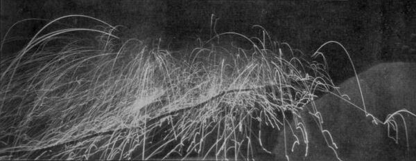
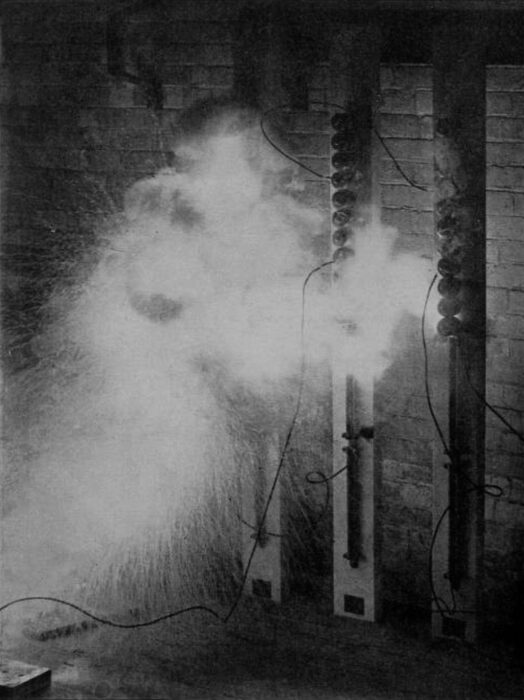
| Fig. 1 -- A 10,000 H. P. Fuse Explosion. |
This does sound simple, but to do it and give continuous service twenty-four hours per day and three hundred and sixty-five days per year has, in practice, been found exceedingly difficult, especially where great amounts of power are involved. All the preliminary experiments were done with small amounts of power, and after a while difficulties were overcome, apparatus was standardised, and fair results were obtained. When it came to larger units and more power, much apparatus which had been perfectly reliable under former conditions proved worthless. Switch-hoards, with their fuses, circuit-breakers, lightning arresters, all had to be modified or redesigned.
It was remarkable how quickly some of the early switch-boards, designed for use in connection with power plants of large capacity, would have the marble reduced to lime and switches and instruments to vapourised copper by the improper working of a fuse or circuit breaker. Even at the present time switch-boards and their accessories are considered the greatest factors of uncertainty in a transmission system.
Some of the experiments made, with the view to perfecting fuses and other apparatus for these uses, were extremely interesting, both from scientific and spectacular standpoints. The illustration shown above is a reproduction of a photograph taken during the "blowing of a specially constructed fuse of 1000 amperes capacity on a 2000-volt circuit, backed by a generator capacity of 10,000 horse-power. Using the term "blowing the fuse is altogether too tame an expression for these conditions. It would better be called exploding," as a great noise is made and a fine tire display is produced.
| |||
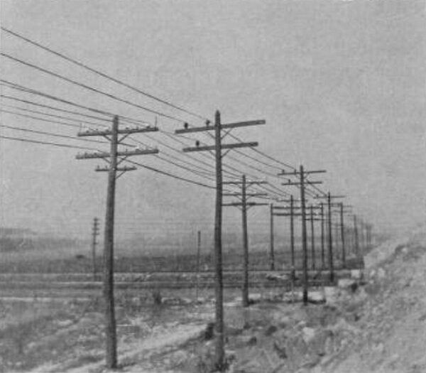
| Fig. 2 -- the Relative Conspicuousness of White and Brown Insulators on Two Different Transmission Lines. |
High - tension, alternating - current fuses have, to a large extent, been superseded by varying forms of circuit-breakers, some of which are absolutely reliable. One of the most important objections to the latter was that they would break the circuit on a momentary increase in current, which occasionally happened when there was no reason to shut off the power. Fuses were well adapted for these overloads lasting only a few seconds, for it takes an appreciable time for them to heat to the melting point; but the trouble comes when they do blow, as they have a decided tendency to not only destroy themselves, but everything in their vicinity. This led to a design of circuit-breaker with a time attachment which is adjustable, so that when an overload occurs the circuit will not be opened until after the lapse of a certain number of seconds, and if the current drops again before this set time is reached the breaker will not open. With this class of protective devices on a large system continuous service is much facilitated. The breakers nearest to, or at, the power house should be set for the longest time, say, six seconds; those on the branch lines should be set for four seconds; and those connecting other lines or apparatus for two seconds. This arrangement insures the continuance of the main line unless the trouble is with itself. One of this type of breakers, without the time attachment, is shown in Fig. 4, in the act of opening a high-tension circuit.
| |||
| Fig. 3 -- Effects of Artificial Lightning Discharge. |
| |||
| Fig. 4 -- A Circuit Breaker Opening on A High-Tension Line. |
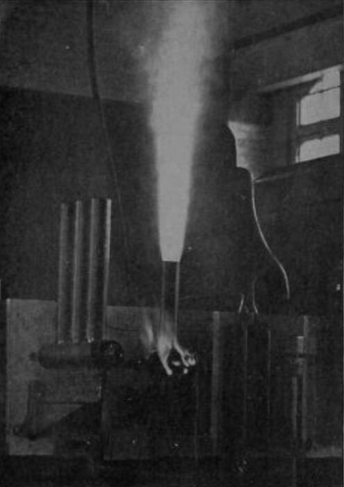
Next in importance to the overload devices of a transmission line comes those that protect the apparatus at its ends from lightning. Most of the lightning arresters built up to the present time have had one of two faults. Either the air gaps between their cylinders or balls were so great that they were no protection to the apparatus, or the gaps were so short that current from the line would follow the lightning discharge and destroy the arrester for future use. This last fault has been overcome by inserting resistance between the series of gaps and the ground sufficient to limit the current which will follow the lightning discharge to such a small amount that it cannot harm the arrester. Many tests have been made to determine the best forms and most effective ways to protect against lightning, but it is so difficult to reproduce ordinary conditions of lightning artificially that improvement in this line is slow, and is usually the result of actual experience. Figs. 3 and 5 show some attempts to test the above-mentioned form of arresters. The test is started by a miniature lightning discharge made by a Roentgen ray set, and the illustrations show the current discharges which follow. With tests of this nature the camera plays an important part, for the brilliancy and noise of the discharge leave the observer in a dazed and undecided state as to what actually happened; but the photograph gives an exact reproduction of what occurred, and can he studied at leisure.
| |||
| Fig. 5 -- Another Artificial Lightning Discharge Effect. |
The transmission line, made of bare conductors stretched at the top of poles and supported on insulators, is in itself quite simple; but when there are thirty or more miles of it, with many thousands of insulators, any two of which being defective, may cause trouble, it is easy to understand the chance for interruption of service. There are a thousand other things to make trouble that no one would ever imagine until they have actually been experienced. Sometimes trees that are apparently a safe distance from the lines are blown on to it during a storm, either causing a short circuit or tearing down the wires.
The large, white porcelain insulators so commonly used are another source of trouble. Being so white, they are very conspicuous, and are, therefore, irresistible to the marksman, who shoots them off, little knowing of, or caring for, the weary hours of tramping and inspection necessary to patrol perhaps the whole length of the line to locate the fault which is shown by the ground detector at the station. After the broken insulator is found, come the care and danger necessary to replace it without interrupting the service. This, although a risky operation, is often done. Coloured insulators can now be obtained, which overcome the temptation to the marksman. Fig. 2 shows two transmission lines, one equipped with white and the other with brown porcelain insulators.
Probably the most exasperating cause of trouble with bare overhead lines is the small boy with a piece of hay-bale wire which he tosses up to see the fire-works. The great display is liable to strike terror to his heart and impress him with the enormity of his crime, so that he will not do it again; but it is possible for an apparently infinite number of boys with the desire to see fire to live within the neighbourhood of a 30-mile line, and it is difficult to locate a boy after his desire has been satisfied.
After once getting started, an arc, under proper conditions, will hold across a surprisingly long distance. A number of instances are recorded of an arc holding between conductors eighteen inches apart on a 10,000-volt line for a length of time sufficient to completely burn off a 350,000-circular mil. cable. A peculiar instance was once observed of an arc, after being started between conductors, continuing to hold while the wind blew it along the line, producing an effect similar to a meteor travelling parallel to the earth's surface. The distance between the conductors on this line was eighteen inches, but this was changed to thirty-six inches to overcome this and other troubles.
An instance of a remarkably long arc holding occurred recently on a circuit breaker panel connected to a 10,000-volt circuit. The breaker was of the long-arm type, that would simply open the circuit by making a long break. The arms were separated by barriers projecting 24 inches from the face of the panel. As the arms came out in the act of opening the circuit, the arcs became connected outside of the barriers, and held long enough to completely destroy the panel.
The majority of transmission lines installed up to the present time have been overhead lines, with bare conductors, supported on insulators at the top of poles; but under some circumstances, such as running through thickly populated districts, or where continuous operation is essential, underground lines meet the conditions better. The underground system offers some advantages in that it is out of sight and less liable to malicious treatment. Climatic conditions do not affect it, and it thus escapes entirely one of the most serious troubles with overhead lines, namely, lightning. Interruptions from falling trees, adjacent fires, storms, marksmen, and the small boy all fade out of sight when the conductors arc below the surface.
There are, however, some drawbacks to this system also, and placing conductors underground does not entirely eliminate troubles from external sources. There are many instances, especially in cities where the labourer digging a trench for water, gas, or sewer pipes, drives a pick or bar through a conduit and into a cable, destroying its insulation. But it is seldom that a well-protected conduit is disturbed, as it becomes obvious, even to a very thick-headed individual, after picking away at well-seasoned concrete for awhile, that it was probably put there to stay, and for some purpose. The one great chance for interruption in the underground system is the breaking-down of the insulation on the conductor, and although excellent cables are made and every known precaution is taken to make them perfect, faults will occasionally develop, and sometimes are most difficult to locate, especially on very long lines. These should be divided into comparatively short sections by switches; then, in case of trouble, the defective section can be easily located and the fault found much more quickly.
Electrolysis is responsible for much cable trouble, destroying the lead covering, exposing the insulation, and thus leading to rapid deterioration. Electrolysis can be guarded against, and, if proper precautions are taken, it can be almost eliminated.
Static discharges on long cables, or those of high capacity, are often the cause of trouble that is thought to be due to defective insulation, and all such lines should be provided with devices capable of conducting away the dis-charge. Even on lines only a few miles long, discharges of this nature, although very slight and scarcely noticeable, will, in time, give trouble. A common place for this to occur is at the cable ends at the point where the lead sheathing stops, discharging between the end of the lead and the conductor, resulting finally in the destruction of the insulation.
| |||
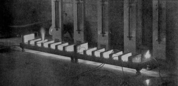
| Fig. 6 -- A Discharge Panel on A 12,000-Volt Underground Line. |
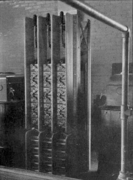
Fig. 6 shows one of a set of discharge panels used at the ends of a 10-mile, 12,000-volt, paper-insulated underground line. The arrester was discharging as the photograph was taken, as can be seen by the small, bright spots at the gaps between the balls. These discharge panels are similar to those built for lightning protection, and are composed of air gaps between brass cylinders or balls, with a resistance connected between the gaps and the ground to prevent a damaging current from following the static discharge.
Ground detectors are a most essential feature of any kind of electric transmission line, for by their use a single ground can be discovered before any interruption to the service occurs, and immediate steps can be taken for making repairs. With the knowledge gained by the past years of experience, it can now be truly said that by using the best advice for designing, the most careful work in constructing, and great diligence in maintenance, power transmission can be made reliable for practically continuous operation.
