[Trade Journal]
Publication: Street Railway Journal
New York, NY, United States
vol. 20, no. 14, p. 463-468, col. 1-2
Overhead Construction and Electric Power Distribution
of the Detroit United Railway System
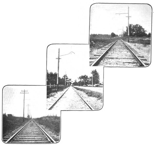
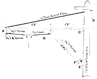
The overhead line construction on the interurban lines of the Detroit United Railway is decidedly varied on the different divisions, because of the different ideas of the original builders of these lines. The illustrations here-with, and with the article on the track department, else-where in this issue, from photographs taken on the different divisions, illustrate this well. However, a certain standard type of overhead construction is now being put in wherever new work is called for. This is shown in the engraving on another page, giving the two forms adopted for future work, one with a
| |||
| Generator Leads Between Stations A and B |
supporting brace below the bracket, the other without. A truss rod is used in both cases, because of the large amount of support it gives with a small weight of material. The drawing shows the bracket fittings of the Ohio Brass Company. The tubing is 1 1/2 ins. and the truss rod 1/2 in. Two figure 8 trolley wires are used. All poles are numbered with miles and tenths of miles from Detroit, which proves a great convenience in many ways. The exact location of track or line defects can be reported by motormen, and it saves the taking of measurements for distances in planning new work or making tests of various kinds.
INTERURBAN POWER DISTRIBUTION
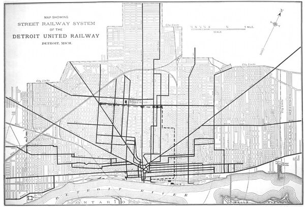
While the system of the Detroit United Railway, taken as a whole, offers splendid opportunities for a comprehensive system of alternating current high-tension distribution with sub-stations for supplying both city and interurban lines, no such comprehensive system has yet been begun, since it is but recently that the four interurban divisions were brought under the same ownership. The power distribution is therefore by a somewhat temporary patchwork of direct current and alternating current. The accompanying map shows the present arrangement of power supply.
| |||
| Map of Detroit City Distribution, Showing Power Houses, Battery Station and Equalization Scheme |
On the Orchard Lake division running to Farmington, Northville and Orchard Lake the power distribution is all by direct current with boosters from a power house at Farmington Junction. On the Pontiac division the distribution is all by direct current from a power house at Birmingham. On the Flint division, running from Royal Oak Junction to Rochester, Romeo, Lake Orion and Flint, there is a direct-current power house, at Rochester, which, with the aid of a booster, feeds south 14.6 miles towards Detroit as far as Royal Oak, and also to Romeo and toward Lake Orion. In the power house at Rochester there is an inverted rotary converter run as a motor from the direct-current bus-bars of the station. This is a Stanley machine of 250-kw rated capacity, but is being run regularly to tide over present emergencies at 100 per cent, without going above its heating or sparkless commutation limit. This converter gives alternating current at 360 volts three-phase from its collector rings. This is raised by step-up transformers to 15,000 volts, and transmitted over two circuits of No. 4 aluminium [sic] aluminum cable to sub-stations at Oxford, 13 miles north, and Atlas, 30.4 miles north. The rotary converters in these sub-stations are started ordinarily (if the voltage on the trolley lines is not being lowered by the presence of a car drawing current between the power house and the sub-station) by starting them as shunt direct-current motors from the trolley line. When the direct-current voltage is so low that it will not bring the rotary converter up to synchronism by this means, the rotary is run up to as high a speed as the direct current will bring it, and the main switch throwing it onto the alternating-current mains is partially closed. By the auxiliary contacts on this switch when it is partially closed, the rotary converter armature is connected with the three-phase bus-bars through an inductance coil in each leg of the circuit. This cuts down the current to a permissible amount until the converter is jerked into step. When this latter occurs, the main switch is entirely closed, connecting the converter directly to the alternating-current bus-bars. Of course, this is heroic treatment to get machines into step, but no evil results seem to come of it. Another method of starting these rotary converters, of course, would be to weaken the fields when running as a shunt motor, and so increase the speed until a point was reached where the machine would synchronize. To do this more field resistance than is ordinarily provided would have to be used. A modification of this plan has ben successfully tried, though not regularly used. This is to run the
| |||
| Some Samples of Overhead Construction |
machine up to the highest speed possible as a shunt motor, cutting in as much field resistance as possible, and then momentarily opening the field circuit altogether, letting the machine run on the residual magnetism in the fields. Of course with a field so greatly weakened the motor speeds up rapidly and must be cut out of circuit before attaining a dangerous speed. As the speed falls, the switch on the alternating current side can be closed as the point of synchronism is reached. As before mentioned , the high-tension lines are of aluminum No. 4. These two aluminum lines are of stranded conductor on Provo type glass insulators made by the Hemingray Glass Company, of Muncie, Ind. Experiences with this aluminum line when first strung have demonstrated the importance of educating linemen who are used to stringing copper to the necessity of allowing a liberal amount of contraction in cold weather, as aluminum contracts more than copper, and is not strong enough to stand the tension that could be put on copper.
| |||
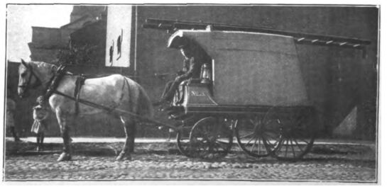
| Emergency Power Wagon, Special Detroit Delivery |
An alternating current generator has been ordered for the Rochester power house, which will do away with the inverted rotary.
The interurban line to Wyandotte is run from the city powerhouses with the aid of a booster and a 280-amp, hour storage batter at Ecorse.
CITY POWER DISTRIBUTION
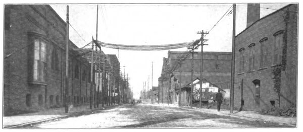
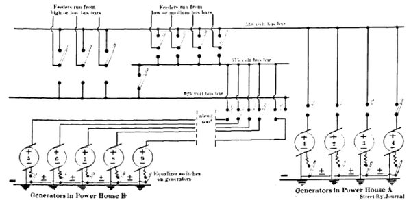
The city power distribution of the Detroit United Railway Company is all by direct current from two power houses, located diagonally across the street from each other near Riopelle Street and the river front. One of these power houses was originally built by the Detroit Citizens' Street Railway Company, and is called Station A. The other was built by the Detroit Railway Company, and is called Station B. Since the consolidation the operation of these two powerhouses has been combined in a rather unusual manner, which, as it affects the electrical distribution, will be described here. The switchboard for both power houses is all combined in one power house, and the two power houses are operated electrically, just as if they were one,
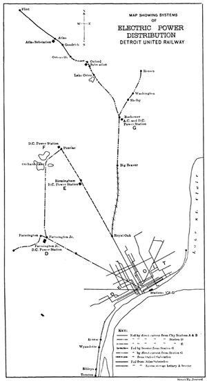 |
| Map Showing System of Electric Power Distribution, Detroit United Railway |
although the engines and generators are under different roofs with a street intervening, and nothing but telephonic means of quick communication between them. The positive generator switchboard leads and shunt field leads in Station B are run across the street to the other power house, and there terminate on regular generator panels. No switches are located in the Station B, save the equalizing switches on the generators, and these are on the negative side. The negative leads have no switches, but are connected permanently to the negative and ground. All other switches are in Station A. The average length of the leads from the Station B generators to their switchboard panels in the other power house is about 600 ft. The generator leads between the two powerhouses are carried on poles just as if they were feeders. The accompanying engraving shows these generator leads between the two power houses at the right side of the street, and also the feeders leaving Station A, at the left side of the street. Only the positive leads are brought to the switch-board in any case, and consequently all switching is on the positive side. The equalizing switches being on the machines, the only main switch needed on a generator panel is a positive switch and circuit breaker. This arrangement has worked to the entire satisfaction of all concerned. Its object, of course, is to simplify switchboard attendance, and to make it possible to run all the feeders from one board. This makes the operation of the two power houses more flexible, makes it easy to shut down either one of the power houses at night, and practically makes one power house of them, as far as carrying the load is concerned. The number and capacity of the generators in operation can be adjusted to the load so as to give the generators a more economical load with this arrangement than if they were supplying different sets of feeders.
| |||
| Stadard Overhead Construction With Bottom Brace |
Another feature of interest about the switchboard is the use of three sets of bus-bars, which makes it possible to run feeders on any one of three different voltages. The diagram below shows the arrangement. Two sets of bus-bars are run the entire length of the feeder board. A third bus-bar runs part of the length of the feeder board. Part of the feeders can be connected onto either the high or low bus-bars, and part can be thrown onto the low or medium bus-bars. Each feeder has a double throw single-pole switch for connecting to either set of bus-bars. There is a paralleling switch between the medium and high voltage bus, so that these can be thrown together. The voltage of the highest bus is about 625, that of the medium 575, and that of the lowest 550 when operated independently. Generators 1, 2, 3 and 4, which are located in Station A (the one in which the switchboard is located) are arranged to connect with the low-voltage bus-bars as shown. Generators 5, 6, 7 and 8 in Station B, across the street, have their main switches arranged to connect the medium or 575-volt bus. Generator 9 in Station B has on its switchboard panel two single-pole single-throw main switches, by which it can be connected to either the medium bus in parallel with 5, 6, 7 and 8, or, on the high-voltage bus-bars, by itself as a 625-volt machine. A new generator now going in will be connected as No. 9 now is. When the two switches on the panel of No. 9 are closed the effect is that of throwing the medium and high voltage bus-bars in parallel, just as if the paralleling switch between the two were closed, and, in fact, both the paralleling switch and the two generator switches are usually closed when these busses are to be run in parallel. The 625-volt bus is run separately when the load is heavy on outlying trolley sections. When there is not such a load, and for purposes of economical loading of machines, it is desirable to run the high and medium voltage bus-bars in parallel, they are so connected. Out of 32 feeders leaving this board, 22 are arranged for connection to the high and medium bus-bars, and 10 can be connected to the low or medium bus. One matter which influenced the arrangement of the switchboard as it exists at present was the fact that the generators 1 to 8 cannot be raised as high as 625 volts. With the present arrangement they can be run on the shorter feeders, while generator 9, in power house B, supplies the feeders requiring the higher voltages, when a higher voltage is necessary.
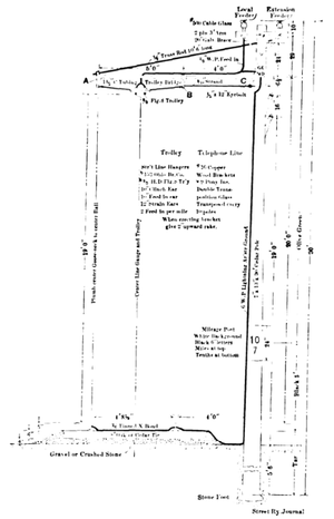 |
| Stadard Interurban Overhead Construction |
In connection with this company's direct-current distribution in the city of Detroit, two sets of storage batteries are employed and on the Wyandotte & Trenton interurban line, which is fed by direct current and boosters from these city power houses, there is also a storage battery. One of these city batteries is located at Station A, and the other in the northern central part of the city. A map of the street railway lines of the city is shown herewith, giving the locations of power houses and the storage-battery station with reference to the system. The feeder lines along each trolley line are omitted for the sake of clearness, but they parallel practically every trolley line, and in addition a special feeder pole line runs directly north from the power house, supplying a number of intersecting streets, and also connecting with a feeder along Forest Avenue, which acts as an equalizer between lines which it intersects. The storage battery is located near Forest Avenue and Third Street, and equalizing feeders are run east and west on that avenue, connecting to the regular feeders at intersecting streets through Westinghouse "Type A" circuit breakers located in boxes on the poles. In shunt around each circuit breaker is a series of five incandescent lamps, one of which is put in a Dayton Manufacturing Company's signal lamp box on top of the circuit breaker box to protect it from injury. When the lamps are lighted, the employees have a sign in the signal lamp that the circuit breaker is open. When the circuit breaker is closed, of course the lamps are out. A lever at the side of the circuit breaker box makes it possible for employees to close the circuit breaker as soon as the trouble has been cleared from the line. These circuit breakers are necessary to make possible the disconnection of any section from the equalizing feeders and storage battery. The use of automatic circuit breakers outside of power houses, sub-stations and cars, where someone is constantly in attendance, is by no means common, nor has it, as a rule, been found satisfactory in most cases where it has been tried. Under the particular conditions here, however, the plan works well. The type of circuit breaker employed is simple and requires little attention, and the closing of these equalizing circuit breakers is not absolutely necessary to the operation of cars, since the direct feeders from the power houses can supply the lines until such time as these circuit breakers may be closed.
After cars cease operation at night on the interurban lines the interurban power houses are shut down, and switches between the interurban and city lines are closed to supply the interurban car houses with light and power for shunting cars.
The overhead emergency wagons used in Detroit differ in several respects from those kept by most city roads. They are pulled by one horse, and consequently are made light, with a ladder instead of a tower. The chief novelty, however, is in having the lower part enclosed. This closed top is simply the strong frame for supporting the ladder covered with canvas as a delivery wagon top.
| |||
| Scheme of Switchboard for the Two Detroit Direct Current Power Stations Operated As One |
In the emergency houses at St. Antoine Street, near Jefferson Avenue, four one-horse emergency wagons are kept in readiness at all times. Two of these are overhead line wagons of the type just described and shown in the accompanying engraving, one is a wreck wagon with tools for derailed cars and broken down wagons, and one is a wagon loaded with hose jumpers for fires.
The work outlined in this article is under the charge of E. J. Burdick, assistant superintendent of motive power.
