[Trade Journal]
Publication: Power
New York, NY, United States
vol. 39, no. 26, p. 906-907, col. 1-2
Coon Rapids Development
SYNOPSIS Five vertical single-runner waterwheels to develop 10,500 hp. on an average head of 17.5 ft. Out-put of plant to serve Minneapolis.
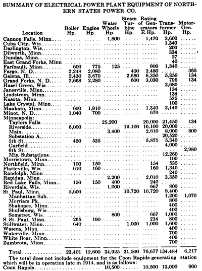
As shown in the accompanying summary of generating and substations, the Northern States Power Co. controls and operates large interests developing power by water and steam. According to the statistics, there is now in operation 76,677 electrical horsepower in generators, driven by 31,500 hp. of steam turbines, 12,600 hp. of engines and 34,925 hp. of waterwheels. By far the largest part is developed within a radius of 75 miles from Minneapolis.
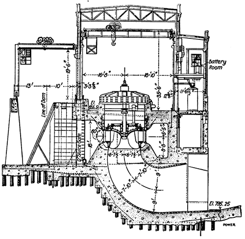 |
| Fig. 1. Transverse Section Through Plant |
The properties here are divided into four main divisions, designated as Stillwater, Minneapolis, St. Paul and Mankato-Faribault. The several municipalities in each of these main divisions are connected by high-tension transmission lines with the main generating stations of the division. The city of Minneapolis and the towns in this division are connected by high-tension transmission lines to the hydro-electric stations at Taylors Falls and St. Anthony Falls, known as the MainStreet Station, and to the large reserve steam station at Riverside, Minneapolis. The entire division is also interconnected through a high-tension trunk line with the steam power house of the St. Paul division. Similar interconnecting systems exist between the hydro-electric and steam stations of the Stillwater and Mankato-Faribault divisions. Within the year it is intended to interconnect all of these divisions, so that a transfer from ne hydro-electric station to another will be possible and permit a number of the smaller steam stations to be shut down.
The latest addition to the Minneapolis division, not included in the foregoing summary, is the development at Coon Rapids, which is on the Mississippi River, about six miles north of the city limits and 11 miles from the Main Street station. H. M. Byllesby & Co., engineers and constructors, have already finished the dam and the power house is under way. By the first of September, it should be in full operation.
| |||
| Fig.2 Part of Dam, Showing Concrete Crest and Tainter Gates |
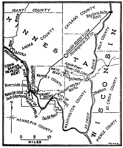
The plant is to have an initial capacity of 10,500 hp., made up of five 2100-hp. units, with space for two more, so that eventually14,700 hp. will be developed. A three-phase transmission line will connect the plant with Minneapolis, and it is intended to build a second line to Anoka. The location of the site relative to the other plants, with the exception of those of the Mankato-Faribault division, is shown in Fig. 4.
The feature of the plant is the low head, which, from previous data taken at St. Anthony Falls, will vary from 13 to 20 ft., and average 17.5 ft. To utilize this head to advantage, vertical single-runner waterwheels were designed by the Allis-Chalmers Co. to turn at 62 r.p.m. The wheels will be directly connected to the General Electric generators rated at 1625 kv.a. and designed to deliver to the station bus three-phase, 60-cycle current at 2300 volts. By delta-connected transformers the tension will be increased to 13,200 volts to lessen the cost of transmission. There are seven transformers having a total capacity of 13,000 hp. and space is provided for three more. The generators are of the suspended type and, due to the low speed, are of large size. Two 300-kw., induction-motor-driven exciter sets will furnish excitation, one to act as a spare. A waterwheel unit was not considered necessary, due to the connection with the other stations. A remote-controlled, electrically operated Switchboard will be installed and small storage battery for operating the oil switches and emergency lights. The layout of the plant is shown in the plan view, Fig. 3, and in the sectional elevation, Fig. 1. The building itself, 202 x 49 ft., will be of concrete, steel and brick.
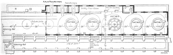 |
| Fig. 3. General Plan of Substructure |
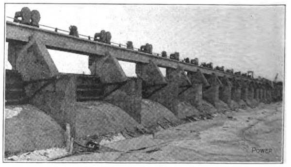
As the dam passes over a small island in the river at this point, the river has two channels, one wider and more shallow than the other. Across the former channel a spillway-concrete dam of the gravity type, 1000 ft. long, was built. The power house, measuring 500 ft. with the retaining section of the dam, was built across the narrower channel; a 560-ft. earth embankment makes the total length of the dam over 2000 ft.
 |
| Fig. 4. Transmission Lines. Near Minneapolis, of Northern States Power. Co. |
For its full length the gravity spillway section of the dam is surmounted by 28 Tainter gates, each being 33 ft. long and weighing six tons. These gates, shown in Fig. 2, raise the pond level 7 1/2 ft. over the concrete crest. They will pass all water not used through the wheels and will be so operated as to maintain a uniform-head water level. The spillway has been designed to pass 80,000 sec.-ft., although 60,000 sec.-ft. is the maximum stream flow recorded. The draft tubes, which are 12 ft. 6 in. in diameter at the wheel and widen out as they proceed toward the tail race, have been designed for a capacity of 1320 cu. ft. per sec. at the average head of 17.5 ft.
 |
