[Trade Journal]
Publication: Electrical Engineering
Chicago, IL, United States
vol. 7, no. 4, p. 259-279, col. 1
TELEPHONY
BY DR. V. WIETLISBACH, OF BERNE, SWITZERLAND.
(Continued from page 196.)
COMPOUND WIRE.
It has frequently been attempted to manufacture a wire uniting the electrical properties of copper with the high mechanical strength of steel, usually by covering a steel core with a copper sheath.
This wire was first used many years ago in America, but did not last, owing to the copper sheath cracking, which soon caused the core to rust and break. It has recently been reintroduced in Europe under the name of bimetallic wire, but more time is required to yield definite results. Through the repeated changes in temperature in summer and winter, and the difference of expansion between iron and copper (0.000,115 and 0.000,172 respectively for each degree Cent.), arises a molecular tension which ultimately loosens the copper sheathing.
The wire is made by forging a copper plate about a round steel bar, which is then rolled and drawn into wire.
Compound wire thus offers a mean between iron and copper, combining the high self-induction of the former with the conductivity of the latter. As appears from the theory of telephone lines, such wire offers great advantages when it is desirable to improve the capacity of the circuit. It would also be advantageous for telephone cables, but we know of no experiments verifying this theoretical deduction.
The bimetallic wire of Martin & Co., in Paris, is made to the following specifications:
 |
Comparing the different kinds of wire, steel, bronze (or hard drawn copper) and compound, for a diameter of 2 mm. (8o mils.) we have the following:
 |
It is not enough to choose the best wire; the line must also be properly erected. In the early days, belief in the importance of good insulation for telephone lines, as well as low resistance, was by no means universal, but the results of long-distance work have now made the necessity of both generally understood.
Insulation has two objects:
1. To exclude from the circuit other currents from neighboring lines or from the earth.
2. To hinder the current in the line from escaping to other lines or to earth.
The possibilities of insulation with a well built and carefully kept line are shown by the measurements of the Indo-European Telegraph Company.
The section between Tiflis and Tauris, 542 km. (339 miles) long, gave, in 1876, an average insulation of 31.8 megohms per km. (20 per mile), never falling in wet weather below 8 megohms per km. (5 per mile). This line was, to be sure, built regardless of cost, and so high insulation is not really necessary, but it should be possible to obtain 1 megohm per km. (5 per mile), even in rainy weather. Below this point a line acquires the familiar properties of a barometer, working very well in fine, dry weather, and very badly in wet weather, when all sorts of inarticulate noises are picked up, together with cross-talk from other lines.
To be sure, cross-talk may also arise from induction, but as soon as we find it to be a function of the height of the barometer or hygrometer, we may safely assume that the insulation also cuts a figure.
The line must nowhere touch external objects, such as trees, twigs, the walls or roofs of houses, nor even swing against them in the wind. A practical rule is to keep wires at least 30 cm. (1 foot) from fixed objects, and at least 1 m. (3 feet) from movable ones, such as the branches of trees, etc. The branches of growing trees must of course be trimmed occasionally.
The supports of the wire are to be suitable nonconductors, preferably of glass or porcelain. Formerly glass insulators were generally used, but glass is easily cracked without the insulation actually breaking or the fault becoming visible, with the result of materially cutting down the insulation. Glass has therefore gradually yielded to porcelain, which is less brittle.
There are two very different kinds of commercial porcelains. The hard paste porcelain, composed entirely of kaolin and feldspar, is very hard to fuse, and requires in fusing a temperature of about 1800° Cent; its fracture presents a smooth, shell-like, sparkling surface. The more fusible quartz porcelain, which is fired at a lower heat and is mixed with quartz and lime or other silicates as a flux, shows a dull, sandy, porous fracture. Its glazed surface looks better than the hard porcelain, and it is much cheaper to manufacture, but it is unsuitable for good insulation, as it allows the current to penetrate, owing to its structure and to minute cracks in the glaze. Besides the quality of the material the form of the insulator is also very important. It should be so designed as to maintain always, even in the worst rains, a strip of dry surface between the wire and the support to which the insulator is fixed.
 |
Various forms of insulators are used in different countries according to local requirements.
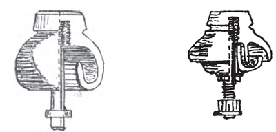
In Europe the porcelain double-shed insulator has come more and more into general use. It is cemented to a suitable iron support with plaster of paris, or screwed fast into hemp which catches in the thread of the insulator and the sharp cuts or screw thread of the supports. The object of the peculiar shape of the insulator is to maintain the dry strip between the outer surface in contact with the wire and the inner surface, which is against the support. The double-bell shape hinders not only the direct access of atmospheric deposits, but also rapid cooling, which would favor the condensation of dew. (Fig. 183.)
 |
In England earthenware insulators are in common use, and they take a glaze of good insulating properties. There is also the well-known insulator of Johnson & Phillips, which has its lower rim turned in and up, so as to form a groove which is filled with oil, thus making the latter a part of the insulating surface. (Fig. 184.)
No deposit can adhere to the oil, which therefore provides the insulation in wet weather. The use of this insulator is advisable only in special cases, on account of the trouble of keeping it in order, which involves occasional cleaning and refilling with oil.
 |
In America glass insulators are still generally used, screwed upon wooden pins or brackets.
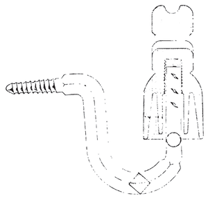
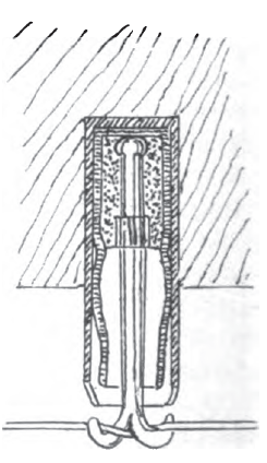
The so-called paraffine insulator may also be mentioned. In a cast-iron cylinder is cemented the glass body to which is fixed the iron hook to receive the line wire, as shown in Fig. 185. Over the cement is poured paraffine, to attain a good insulating surface.
An immense number of forms of insulators have been devised without materially improving their effectiveness. A good insulator should maintain a permanent insulation resistance between line and support of 300 megohms, which is easy enough in dry weather. The quality of the insulator is shown by its holding this insulation in wet weather.
Any insulator that falls below 100 megohms in rainy weather is to be set down as faulty.
To test insulators before mounting the following method may be applied (Grawinkel & Sleeker):
The insulators screwed to their supports are fixed on the back of a well-closing zinc-lined case. A sprinkler at the top of the case pours down a fine, steady rain, which runs out at the bottom. After sprinkling for a given time the insulation is measured, the galvanometer being connected between the zinc lining and a wire attached to the insulator in the same way as a line. The wire may traverse a number of insulators if desired.
Porcelain insulators are usually mounted on malleable iron supports provided with sharp cuts, or better, with screw thread to grip the hemp with which they are wound before being screwed into the insulators, the holes in the latter being threaded for the purpose. After screwing them solidly together all superfluous hemp is trimmed away. The cementing is sometimes done with sulphur or plaster of paris, which, however, hinders the replacing of broken insulators.
The following is the English P. O. recipe for cementing insulators:
CEMENT FOR FIXING BOLTS IN INSULATORS.
Engine ashes, two parts; river sand, one part. To be well mixed, placed in a ladle, and heated over a gas and air burner.
Resin, broken small, is then added in sufficient quantity to mix the above into a fairly thick paste.
Pour the paste into the insulators and drop the bolts into place, the ends being previously warmed. Force the bolt to bottom of hole.
Put aside to cool and set.
A frame with holes in bottom board for insulators, and in top for bolts, will be found convenient.
FIXTURES.
The insulator pins are attached to the roof fixture, which supports the whole line system. In mounting fixtures, care is to be taken to run the lines as straight as possible to the distributing points, so as to facilitate supervision of the whole plant, and the identification of the wires. The wires are to be run well apart, so as to avoid contacts and tangles when swung by the wind. Wires of 2 to 3 mm. (80 to 120 mils.) are usually set 30 cm. apart (1 foot) horizontally, and 40 cm. (16 inches) vertically; finer wires, say 1-l/2 mm. (60 mils.) being set 30 cm. (1 foot) by 15 to 30 cm. (6 to 12 inches) apart, respectively; the longer the spans the greater the distance.
For small exchanges and lines throughout the country, creosoted wooden poles may be used, but inside larger cities it soon becomes impracticable to carry heavy routes through the streets, so that resort is had to housetop poles, or fixtures, as they are called.
To two or more uprights are attached cross-arms carrying the insulator pins. The fixtures were formerly of wood, but iron is preferable, and is used exclusively in all modern work in Europe.
The uprights may be iron pipes, which are readily cut to the required length, and which may even be built up in sections. If malleable iron is used, pipes of 50 to 75 mm. (2 to 3 inches) in diameter, with metal 5 mm. (0.2 inch) thick, will suffice. Steel tubes have lately been used in Germany, and may be still lighter, while retaining the same strength, thus reducing the load on the roof.
Angle or T iron of 50 to 70 mm. (2 to 2 3/4 inches) width and 7 mm. (0.28 inch) thickness is also used. The cross-arms carrying the insulators are usually of U or T iron. In Germany they are made of two iron strips 30 by 6 mm. (1.2 by 1/4 inches) riveted together 20 mm. (3/4 inch) apart, the distance being maintained by iron rings on the rivets, as well as on the insulator pins, between the strips.
The cross-arms are attached to the uprights by means of rings or clips. Fig. 186 shows a strap-iron cross-arm attached to a tubular upright. This construction is suitable only for light wires.
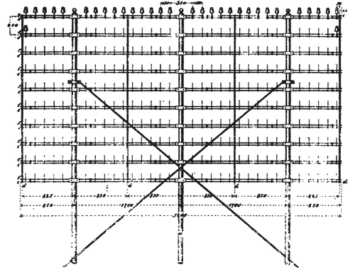
Fig. 187 shows a fixture for 300 wires with three uprights. The cross-arms are braced at the ends and between the uprights, for the sake of solidity, by means of a 7 mm. (0.28 inch) rod passed through holes in the cross-arms and covered with sections of gas pipe between them.
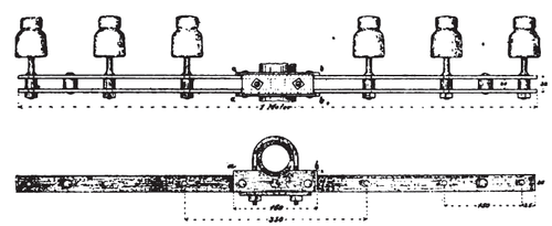 |
One end of the rod is bent at right angles, while the other is threaded and carries a nut.
The insulators are only 15 cm. (6 inches) apart on the arms.
To allow access to the upper arms, the insulators next the uprights are 35 cm. (14 inches) from the uprights.
 |
Fixtures are to be so mounted on the roofs as to allow as much room as possible between the wires. If the lines run straight across the fixture, it is to be mounted at right angles to the course, but if they turn at that point, then the angles should be cut so as to give an equal spacing of the wires on both sides. A variation from this rule of 10 to 20 degrees in either direction is allowable if required by the shape of the roof.
Let d be the distance between the wires of any horizontal layer, and w the angle between the span and the plane of the fixture, then the distance between the insulators on the cross-arm is
 |
Let u be the angle between the two spans at the fixture, and a be the horizontal separation required between the wires on one side and b that on the other side, then the angle w of the fixture and the distance between the insulators on the arms are determined by the equations (Fig. 188)
 |
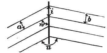 |
Fixtures are to be set up as nearly as possible parallel or at right angles to the ridge of the roof, because they are thus most easily fastened to the frame of the roof, and the above formula then serves to determine the distance apart of the insulators, which is to be reckoned for the side where the angle w is the smaller.
The uprights are best attached to the roof by being clamped to the main rafters, and if no suitable beams are found they must be specially added. It is essential to prevent water from running down the uprights into the roof, which may be done by means of sheets of metal soldered to the uprights. It is sometimes impracticable to carry the uprights through the roof, in which case the fixture is mounted on a frame made up of T and angle iron, fitted to the roof. To prevent the fixture from being pulled away by an unequal strain on either side, it may need to be anchored by means of braces and guy-wires, the latter to be frequently looked after, as they stretch under the effect of changes of strain and temperature, and may thus become useless. (Fig. 189.) An important point is the proper distribution of main routes from the central office into branch routes and individual lines. It is well to extend the fixture horizontally rather than vertically, as far as possible, for the sake of stability, high fixtures being more easily pulled over than low ones. There should always be free wires available for new subscribers in the lower layers and the side wires, to avoid crosses and contacts. The parallel course of wires is to be maintained as far as possible, to facilitate inspection.
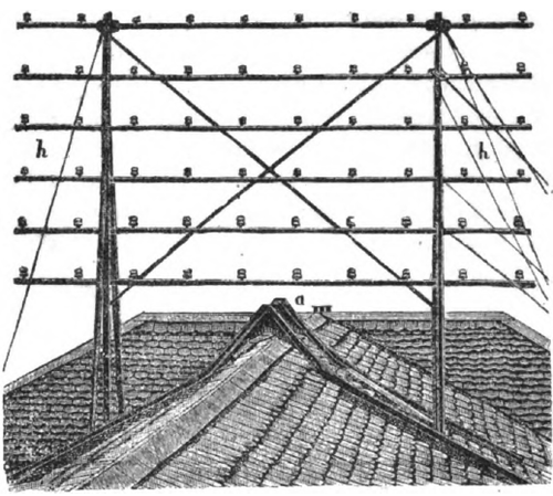 |
Fig. 190 shows the distribution of a route of 60 wires into various branches.
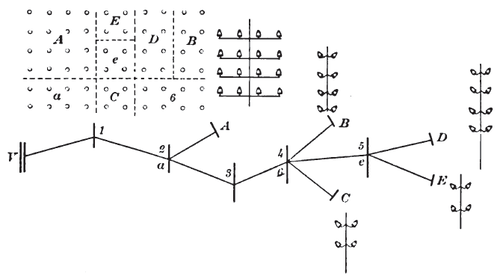 |
From the central office to fixture No. 2, all the sixty wires are run in six superposed rows of ten each. At fixture No. 2 is taken off branch A (4 by 4 wires) to the left. In planning fixtures 3, 4, etc., we leave the section a behind at No. 2, for subscribers in the vicinity. At No. 4 section B branches off to the left with eight wires, and another section to the right with four wires. The eight wires of section B are left behind as a reserve. At No. 5 finally the route branches into section D with eight wires and E with four. The balance e we leave as a reserve.
The fixtures will usually be set about 100 meters (no yards) apart, but this spacing cannot always be maintained for want of suitable places to mount them.
The roof for a fixture should fulfill the following requisites:
It should be in the line of the route from the central office, and be approximately on a level with the preceding and succeeding ones.
The space between successive fixtures must be free of chimneys, trees or other obstacles, and it is desirable to have the same freedom in all directions, to facilitate the running off of branches and single lines.
The roof must be suitable for mounting and fastening the fixture, both as to form and stability, or be adaptable thereto at no great expense.
And finally — last, not least — the landlord's permit is to be got, and perhaps paid for.
The obtaining of suitable housetops is a long and troublesome job. Departures from the original route are often unavoidable, involving inconvenient turns and unequal spans, in order to get through somehow, resulting in spans of 30 to 200 meters.
On the lesser routes simpler fixtures may be resorted to.
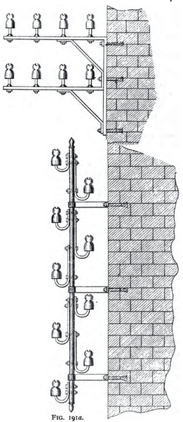
Fig. 191 shows a roof pole, for attaching to a gable end; Fig. 1910 a bracket for the facade of a house. When impracticable to mount fixtures on roofs, poles are to be set, and for durability it is well to make them of iron, if for use inside towns. Various forms of such poles are in use. Fig. 192 shows one built up in latticework, of plate and T iron, usually the best construction if space allows. The base is solidly anchored in concrete, and as this is a nonconductor, the pole is to be provided with a ground plate.
Smaller poles, 8 to 15 meters (25 to 50 feet) high, may be made of iron pipes, or of square or U-iron, or wood.
 |
|
When the cross-arms are very long, two poles are to be set up side by side, with the arms clamped to them, as in roof fixtures.
 |
The fixture on the exchange roof must be of special construction. It differs from the others mainly in two ways: it must carry a much greater number of wires, and the pull on them is only in one direction.
In a small exchange a comparatively simple model may be used. If the central office roof is high and steep, openings may be cut before which are set cross-arms with insulators. Dormer windows afford easy access to the insulators. Such a contrivance is strong and cheap. If the roof is low a sort of tower may be built, and supports for the insulators attached to the outside walls; or the insulators may be mounted directly in the tower. Thus 400 to 600 lines may be accommodated, but the system offers no special advantage, as it is rather expensive and limits expansion beyond a certain point.
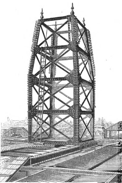
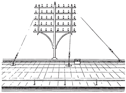
If a special tower must be built, then it is better to erect on the roof a frame of uprights and cross-arms, similar to the ordinary fixtures, but larger. This frame is best made square, but in special cases it may be a hexagon or octagon. At the start it need be fitted only for present needs, with room for extensions. The sides are bound together by stays, so that the pull in all directions maintains the equilibrium and only the difference of strain is left to be borne by the structure. A similar construction on a smaller scale may be applied to the cable distributing points. (Fig. 193.)
|
There is a central office fixture in the form of a cupola, adapted to the architectural style of the building. Its frame is made of U-iron arches, to which are bolted lighter U-irons horizontally, bent into circular form. These take the place of cross-arms and carry the insulator pins. Such a cupola may receive up to 2,000 wires.
Such a tower looks very fine, but is not so practical as the square form, where the wires are more readily run, and are more accessible.
|
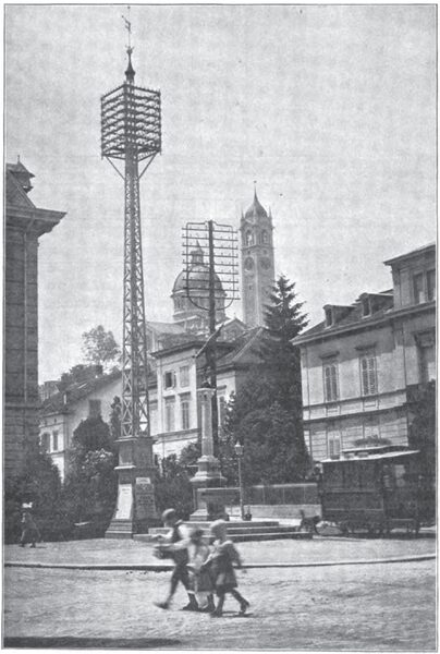
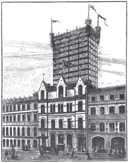
The largest wire tower ever built is the one shown in Fig. 194, in Stockholm, capable of receiving 8,000 wires, of which 2,000 already exist. (This is likely to remain the largest in the world, for the tendency is to supersede the tower, for large exchanges, through the use of cables.) In many places difficulties are met at only 2,000 or 3,000 overhead wires, while in others it may be possible to bring together 8,000 or 10,000, according to circumstances or engineering skill. When the wires can no longer be run overhead, resort must be had to cables.
STRINGING THE WIRES.
The pole or fixture once set up and the insulators mounted, the principal operation still remains — the running of the wire.
The most important point to be regarded here is to avoid everything endangering the mechanical soundness of the wire, that is, mechanical injuries of every sort, such as bends and twists. The wire should never be uncoiled by hand, but should be unwound from a reel, as otherwise every turn makes a twist, a good demonstration of the mechanical results being obtained by treating a roll of telegraph paper in the same manner. For pulling wire over housetops from one fixture to another, a rope is first to be got across. The distance to which the wire can be carried at a stretch depends on the size of the coils supplied by the manufacturer which should be approximately uniform, say 500 to 700 meters (5-16 to 7-16 mile), with 1-1/2 mm. (60 mils.) wire. A rope is run over the successive fixtures for the required distance, preferably double so as to make a return line, passing Over a pulley at each end and at each fixture. The wire is attached to the rope at the starting point and pulled along with it, a lineman being stationed not only at each end, but also if need be at each fixture, especially if there are corners to be turned. On reaching the other end the wire is detached from the rope and is then fastened to the insulators at all the fixtures, with a minimum of contact surface between wire and insulator — for the less this contact the better the insulation. A certain given amount of sag is to be allowed between each two fixtures, to be exactly the same for all the wires of the same span, so as to keep them as nearly parallel as possible. This condition is important, to prevent crosses and tangles when the wires are swung by the wind.
 |
It would be preferable to attach the wire to the insulator only with a soft tie wire, as shown in Fig. 195, but as copper wire has a smooth surface it slips through the tie wire when the strain is not equal on both sides, as is the case with spans of unequal length. To prevent this slipping it is best to give the wire a turn about the insulator and then tie it.
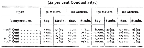
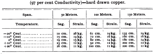
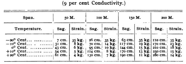
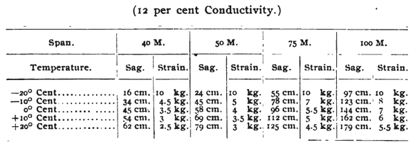
The tighter the wire is pulled up the less the sag, but the tension allowable is limited according to the breaking strain of the wire. Besides, as the length of the wire varies with the temperature, the sag is to be adjusted so that the mechanical strength of the wire is not endangered, even in the coldest weather to be anticipated. The greater the sag the less the strain, but the greater the danger of crosses in a high wind. It is therefore best to strike a medium for the sag. The considerations on which its calculation depends in particular cases remain to be treated later. Following are tables for the sag in some of the commonest cases.
The sag is independent of the size of the wire, but the strain on the wire is proportional to the weight, which increases with the cross section, that is, as the square of the diameter. The breaking strain, however, increases in the same proportion, so that with the same grade of wire the sag is approximately equal for all sizes under similar circumstances. To be sure, a heavy wire has a slightly lower proportional breaking strain than a light one, but the difference is very small and dependent on incidental features in its manufacture. It suffices, therefore, to know the proper sag for different grades of wire, independently of the diameter.
In the tables, under the head of Strain, is given the pull per square millimeter of cross section. To get the total pull on the wire, this figure is to be multiplied by the cross section in square millimeters.
A.—BRONZE WIRE OF 80 KG. BREAKING STRAIN PER SQ. MM. (42 per cent Conductivity.)
 |
B.—BRONZE WIRE OF 45 KG. BREAKING STRAIN PER SQ. MM (97 per cent Conductivity)==harrl drawn copper.
 |
C.—COMPOUND WIRE OF 80 KG. BREAKING STRAIN PER SQ. MM.
 |
D.— STEEL WIRE OF 140 KG. BREAKING STRAIN PER SQ. MM. (9 per cent Conductivity.)
 |
E. — IRON WIRE OF 40 KG. BREAKING STRAIN PER SQ. MM. (12 per cent Conductivity.)
 |
Translation of these tables into English weights and measures results in such clumsiness that we give only the simpler and more convenient figures of the metric system.
With bronze wire one-fourth the breaking strain is utilized at ordinary temperatures, —10° to 20° Cent. (50° to 68° Fahr.). At lower temperatures the strain is much greater, but no rupture need be feared, for the wire stretches a good deal, thus relaxing the strain. As the elongation is not uniform, a readjustment of the sag may become necessary.
With compound wire the usual standard is to work to one-sixth the breaking strain at the freezing point. The sag varies with the temperature about the same as in the case of hard copper wire, and is to be determined in the same manner. Exact data as to the behavior of this wire are not available. With iron and steel wires it is usual to work to one-fourth the breaking strain at the lowest ordinary temperature, say —20° Cent. (—4° Fahr.) A larger margin of safety is advisable than with bronze wire, because the rupture of the wire may endanger a whole row of fixtures, owing to the higher breaking strain.
The figures given for the sag are to be taken as minima, and it is generally advisable to allow ten to twenty per cent more.
If the spans on both sides of a fixture are equal, the strain will also be equal and remain so at all temperatures. But if the spans are unequal it is still possible to attain equal strains on both sides at a given temperature. If the wires are strung according to the above tables, then with bronze wire the strains are equal on both sides at 10° to 20° Cent., and with iron or steel wire at —20° Cent. If the temperature changes, then the strains become unequal; with bronze wire the change in the longer span being the smaller, with iron and steel wire the greater. On the other hand, the accidental loading of the wire through snow, ice or the pressure of the wind, always affects the long spans more than the short ones. To resist this additional strain it is necessary to brace or stay the fixture, which usually has only to support the difference between the pull on either side. When, however, the wires on one side are broken or cut away, through a heavy fall of snow, or an accident, such as the burning of a house which carries a fixture, the fixture nearest the brake might be pulled over, then the next one, and so on until the whole route is destroyed, owing to a purely local accident. This is just what happened to the Antwerp telephone system in 1885, and the case stands by no means alone.
It is therefore advisable to build the fixtures so that each one will stand the combined strain of all its wires on either side alone.
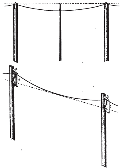
The sag can usually be pretty closely estimated by the eye, but measurements are advisable in important cases. This can ordinarily be done with a stick held against the wires in the center of the span. Then by sighting across the stick from one fixture to the other, the wire is let down until the required sag is shown on the stick. Taking the sight in this way is often difficult, as in crossing a river or low ground, in which case the proper sag may be attained by sighting on points laid off on the fixture uprights, the curve in the wire being brought into line with the two points. (See Fig. 196.)
 |
There is still another method, which consists in measuring the strain instead of the sag, adjusting it to the sag required, by means of a spring dynamometer. This instrument has a strong steel spring coiled in a brass case and carrying a hook, or a frog clamp, as it is called, projecting from the case. As the hook is drawn out the tension on the spring increases, and can be read off by means of a scale engraved on the strip between hook and spring. The wire is fixed in the clamp and pulled in by means of the instrument until the proper tension is attained. (Fig. 197.)
 |
Tie wires should always be of the same metal as the line wire, iron wire being tied with iron, copper wire with copper, to avoid injury from local galvanic action, which is very slight or even nonexistent in dry weather, but is quickly generated by dampness. This phenomenon may also arise when iron and copper wires are run on the same fixture, the former always giving a negative current, the latter positive. On a line one mile long a maximum current of 0.01 milliampere has been obtained. The strength of the current is dependent on many elements, such as the distance between the wires, the kind of insulators used, as well as cross-arms (wood or iron), etc. The phenomenon is due to the fact that the different metals, copper and iron, with the damp surfaces between them, form a galvanic battery. The negative electrode (iron) is of course the one to suffer chemical decomposition, and if used as tie wire for copper it would be destroyed and let the line wire loose. This process would be rapid on account of the slight resistance between the line and tie wire, so that the current produced would be comparatively strong.
Just as between iron and copper wires, so may this action take place between the copper line wire and its iron supports, but the high resistance renders the current so weak that years must pass before any effect is appreciable. A knowledge of such currents is needful, however, in order to execute exact measurements of insulation and capacity. They contribute, also, to the noises which often interfere with speaking in bad weather.
At the central office the line is run to the lightning arresters through insulated wire. This, however, is not to be soldered direct to the line wire under tension, which would be weakened by heating. At the terminal insulator, therefore, an end is left on the line wire long enough for a soldered joint with the inside wire, which must be waterproof and at the same time remain uninjured by housetops, conditions not easy to fulfill, seems to give the best results.
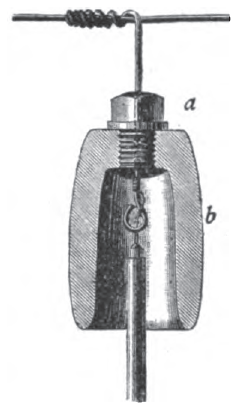
In Germany the wire commonly used for this purpose is covered with lead, which is a good protection to the insulation. The joint must then, however, be kept dry, to avoid an escape of current over the damp surface of the insulating material to the bad covering. The joint is therefore protected by an ebonite funnel, as shown in Fig. 198.
 |
The insulated wires are carried through the roof to the lightning arresters in special metal-lined shafts, or other suitable channels. The main thing is to prevent water running down the wires into the shaft. It is also desirable to protect the wires themselves as completely as possible from the weather by means of the metal shafts or pipes. Wood is to be avoided on account of fire risks.
(To be continued.)

