[Trade Journal]
Publication: The American Telephone Journal
New York, NY, United States
vol. 6, no. 21, p. 298-300, col. 1-2
POLE LINE CONSTRUCTION
Article I. GENERAL DESCRIPTION AND MATERIALS
By J. W. LATTIG
ONE of the most serious mistakes of the Independent telephone companies is poor construction. They have employed materials and methods that were anything but standard, and, unfortunately, many of them still are continuing this practice. While this has been true in many systems, in both inside and outside construction, it applies particularly to pole-line construction.
The United Telephone and Telegraph Company has during the past few years absorbed a great many small Independent companies in Pennsylvania, Maryland, Virginia and West Virginia. In many instances the entire pole-line plant has had to be rebuilt.
 |
In rebuilding these pole lines the United Company has found it the most economical plan to employ uniform and standard specifications. Below will be found complete specifications as used by this company for constructing a thirty-five foot pole line, fully illustrated by drawings:
ULTIMATE CAPACITY. The line shall have an ultimate capacity for forty wires hard-drawn copper, as hereinafter specified.
ROUTE. The pole line shall be located along the most direct and practicable system of highways. It shall only cross private property to avoid abrupt turns, detours, trees, or other obstacles that may make such a crossing necessary. Locate poles in a straight line as far as practicably possible ; make all necessary turns on one pole, guying pole on which the turn is made by a double-head guy, taking strain from each direction in line with route, all guying to be of the most suitable standard method as per drawings.
RIGHT OF WAY Permanent rights of way are to be obtained for every pole, including wires and attachments to be placed there-on. All rights of way so obtained shall be drawn up on regular printed forms of this company, unless specially authorized to the contrary by the general superintendent.
POLES. The standard poles shall be of the best quality live red cedar or chestnut wood, squared at both ends, reasonably straight and well proportioned from butt to top, and of the following dimensions:
Red Cedar Chestnut
Circum. Circum. Circum. Circum.
Length. at top. 6' from butt. Length. at top. 6' from butt.
30 feet. 25 inches 36 inches 30 feet. 25 inches 35 inches
35 feet. 25 " 38 " 35 feet. 25 " 37 "
40 feet. 25 " 43 " 40 feet. 25 " 41 "
45 feet. 25 " 47 " 45 feet. 25 " 45 "
50 feet. 25 " 50 " 50 feet. 25 " 48 "
All poles shall be subject to the inspection of this company at points of delivery. Any pole failing to meet the requirements of this specification will be rejected.
GUY STUBS AND ANCHOR LOGS. The quality of material for guy stubs and anchor logs shall conform to the requirements for poles. Guy stubs shall not be less than 25 inches circumference at top. Anchor logs shall not be less than 22 inches in circumference, and not less than 5 feet in length.
POLE BRACES. Single braces shall conform to specifications covering poles. Double braces shall not be less than 18 inches circumference at top.
 |
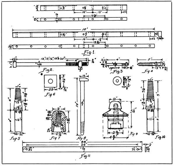
CROSS ARMS. All cross arms shall be thoroughly seasoned, straight grained, Norway or yellow pine, free from such sap wood and knots as would weaken them . They shall be 10 feet long, 3inches thick, 44 inches deep, and otherwise as shown in Fig. 1. All cross arms shall be thoroughly painted with two coats of metallic paint, mixed in the ratio of 7 pounds dry paint to 1 gallon of pure linseed oil, to be applied with a brush.
PINS. All pins shall be of good quality, sound, clear, split locust, free from sap and knots. The standard pin shall be 1½ inches in diameter, and otherwise as in Fig. 5.
INSULATORS. The standard insulator shall be that known as the Hemingray long-distance regular (Fig. 7).
IRON AND STEEL FITTINGS. All iron and steel fittings shall, unless otherwise specified, conform to standard specifications adopted by bridge builders and be galvanized in such manner as to withstand tests hereinafter specified.
CROSS-ARM BRACES. Each cross-arm brace shall be 1 1/4x1/4x28 inches, iron and galvanized, the galvanizing to stand tests hereinafter specified. A pair of cross-arm braces shall consist of two braces 1 1/4x1/4x28 inches, one 5-inch galvanized fetter drive screw, 2 galvanized 3/8 inch carriage bolts, and 2 galvanized washers to each carriage bolt (Figs. 3, 4, and 11).
CROSS-ARM BOLTS. Each cross-arm shall be fastened to pole by one galvanized iron bolt 5/8 inch in diameter and proper length to go through arm pole and washers, allowing all threads in nut to take hold. Each bolt shall be provided with two galvanized iron washers of style and dimensions shown in Fig. 6.
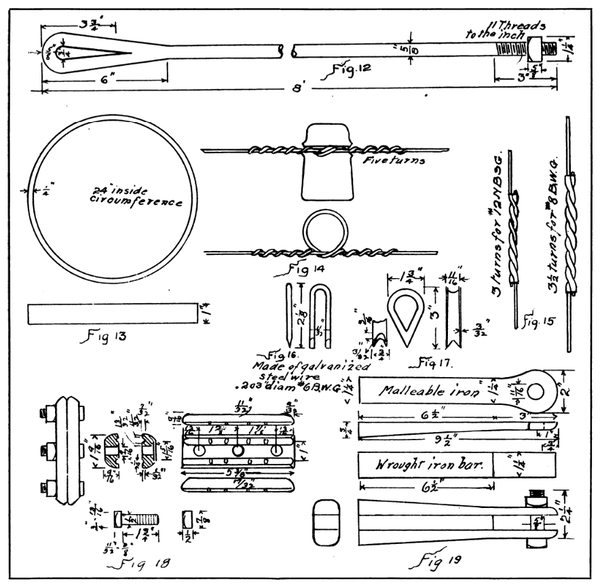
GUY RODS. All anchor guys shall be attached to galvanized iron rods, 5/8 inch in diameter, of style and dimensions shown in Fig. 12. Each guy rod shall be provided with one nut and one galvanized iron washer, as shown in Figs. 6 and 12.
THIMBLES. Galvanized iron thimbles of the style and dimensions shown in Fig. 17 shall be used in attaching guys to guy rods.
POLE STEPS. All pole steps shall be of 5/8-inch diameter, 10 inches long, galvanized iron, style and dimensions shown in Fig. 8.
POLE RINGS. Pole rings, when used, shall be 23 inches circumference inside, 1 inch wide, 1/4-inch thick, galvanized iron, and shall be used on corner poles, otherwise shall be as shown in Fig. 13.
LIGHTNING RODS. Every tenth pole shall be furnished with lightning rod, made of No. 6 extra B. B. galvanized iron wire, as hereinafter specified.
GUY CLAMPS. Guy clamps shall conform to the standard specifications, which are as follows:
Dimensions. The guy clamp shall be of the style and dimensions as shown in Fig. 18. Special care is to be taken to have the log curve of the groove the same in both parts of the clamps.
Material. The guy clamps shall be of the best quality of [sic] maleable;malleable iron. The bolts are to be of steel and have a breaking strength of not less than 80,000 pounds per square inch.
Finish. The castings shall be smooth and free from imperfections. The threads upon the bolts are to be carefully recut after galvanizing.
Galvanizing. The guy clamps, bolts and nuts shall be galvanized and capable of standing tests hereinafter specified
EDITOR'S NOTE. Mr. Lattig is the general superintendent of the United Telephone and Telegraph Company of Pennsylvania.
