[Trade Journal]
Publication: The Electrical Times
London, England
p. 404-406, col. 1-2
OVERHEAD POLE LINES.
NOW that the Americans are talking of 150,000 volts, and learning to regard 60,000 as quite insignificant, it becomes interesting to enquire how far we have progressed in this little country so bountifully supplied with water, yet skimped of water-power. Our highest pressures are somewhere in the neighbourhood of 0.15 of the latest Yankee ideal. But, for all that, in a quiet way we already have some solid experience to go upon, and have learned many lessons in preparation for the day when better conditions render a very distant supply prom the pit-mouth really profitable.
| |||
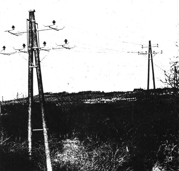
| Carlin How Pole Line at Brotton. |
The able paper contributed to the Institution of Electrical Engineers recently by Mr. Christopher Wade, as the result of pole tests which he superintended for his firm, Messrs. Richard Wade, Sons and Co., Ltd., of Hull, is sufficiently fresh in the memories of our readers for us to be excused any detailed references to its contents. This firm, which is amongst the largest suppliers of poles for all purposes in this country, has from time to time given the benefit of much practical experience to engineers interested in extra high tension transmission, and for some of this information we are indebted in the following notes. First, however, we may illustrate a few points of recent progress in the construction of overhead pole lines for the purposes of carrying power over comparatively open country. To the courtesy of Mr. A. B. Gridley, manager of the Cleveland and Durham Company, we owe these photographs.
The leaning of engineers concerned in the erection of over¬head pole line distributions is undoubtedly towards wooden poles, on account of their cheapness of preparation and erection, and the flexibility with which they resist wind stresses. The sanme argument applies to other conditions attendant on the suspension of wires, some of them of heavy weights, and having long spans across a country subjected to the full force of foul weather. The only objection to be met with in this connection is the extraordinary aestheticism of some local bodies who fear that the architectural beauties of mining villages will be seriously impaired by the use of wooden poles. Many people complain that they resemble telegraph poles in appearance, and where there is more stubbornness, it may be necessary to substitute steel for wooden pole construction. The cost of upkeep of wooden poles appear slight, provided that in the first instance precautions are taken to avoid the effects of rot, and this is usually accomplished by means of creosoting or similar methods. In this connection it should be mentioned that it is not sufficient to obtain poles in a rough state, creosoted at the works and cut to the requirements of the pole erection after delivery on site. It is preferable to have the poles fitted together and prepared by the manufacturers before delivery, so that the creosoting can be effected after all holes and incisions are made.
Except for short spans and light wires, the practice of adopting a single pole is by no means universal structure being either in the shape of an 'A,' or where a large number of wires have to be carried and spaced considerably apart, as at a terminal station, in the form of a letter 'H.' The 'A' pole with a spread at the base of about one-eigth of the height of the pole above the ground is stronger than a single pole of equal area by about four-and-a-half times when the stress is at right angles to the wires, and at least twice as strong when it is in the direction of the wires. The chief source of weakness is the method of tieing the wires, and our first illustration shows the type of 'A' pole, which was adopted by the Cleveland and Durham system on the 'Carlin How' pole line. It will be noticed that the cross arms are of channel iron and supported by means of thin strips to a point about one-eighth down the 'A' pole support, to prevent twisting under the motion of undue pressure. A further iron structure is provided round the top junction of the poles stiffened by vertical members standing at some distance from the pole in the normal section of the line. Care is taken to cut into the pole as little as possible, the channel irons being fixed by means of bolts passing through the woodwork and supported by washers of large surface. All iron work is earthed by means of an earth wire passing round the bolts, thus making metallic contact to every conducting part of the support.
It will be noticed that the key block of oak near the top of the poles is made extremely long, and then is secured by means of a transverse bolt. This is made deep in order to reduce any tendency for it to twist when the poles are under had, because if this occurred it would have the effect of forcing the poles apart at the top.
| |||
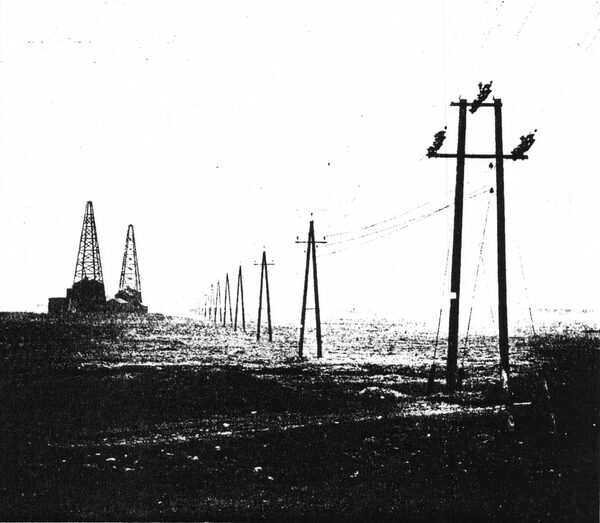
| Hartlepool Pole Line, Greathum Marshes Section. |
The particular pole line illustrated in Fig. 1 is for a 20,000 volt double circuit carrying 0.025 square inch conductors. The insulators used are of the brown pot variety, treble petticoated, and a special arrangement, used in some parts of this line for tying the wires to the insulator, will be noticed in the illustration. This particular line traverses a route of 2.1 miles and so far has been immune from breakdown.
One of the troubles which has been experienced has been the enterprise of small boys who regard any pole as an invitation to exhibit their climbing powers, and a notice has, therefore, to be placed on each pole that the wires are dangerous, and in addition barbed iron wire is wound round the poles at such a height as not to constitute danger to any ordinary passer-by, but to be effective enough to keep off climbing intruders. The line is, at any point where there is a probability of its falling to the damage of passers-by, put to earth by means of the channel strips, which will be noticed in the first illustration. These constitute a valuable means of protection, inasmuch as should any wire break, the loose ends would immediately drag the wires in close proximity with the porcelain insulators down to the catches and immediately put them to earth through the channel iron support and earth wire attached to the pole.
The second illustration gives another example of a 20,000 volt pole line carrying 0.10 square inch copper line wires, and No. 13 S.W.G. telephone wires. This pole line runs to Hartlepool along 5 ¾ miles of route. The arrangement of shackle insulators on the pole nearest the foreground will be noticed.
| |||
| Grangetown to Grisbro' Pole Line. Eston Road Crossing. |
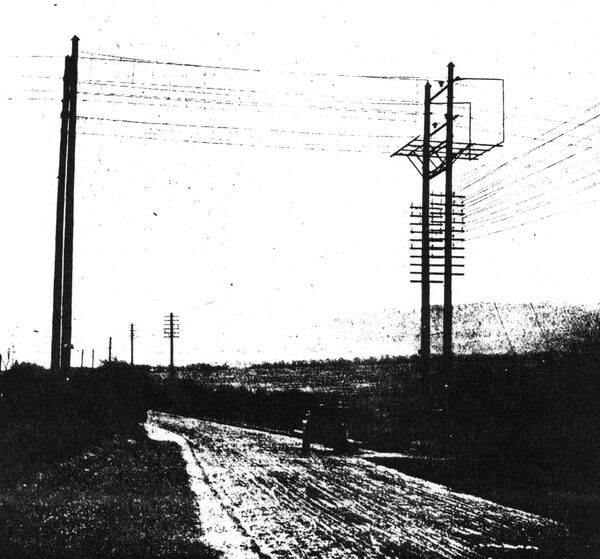
Reference has been made to the usual means of earthing pole line circuits in case of breakage. Where, however, additional danger is involved by the passage of wires over roads or over low potential circuits, such as telegraph wires, further precaution is necessary, and the third illustration shows the mode of protection for a 20,000 volt pole line crossing a road. The line wires carried are of 0.05 square inch section, and the H' pole device is used. Surrounding the wires so as to form a metallic basket is arranged a series of conductors efficiently connected to earth so that should one of the wires of the crossing section break, there would be an immediate short circuit to earth. This arrangement is in accordance with the requirements of the Post Office authorities.
Trouble has not hitherto been experienced as the result of wind pressure, although it is believed that the Board of Trade regulations on this point provide a factor of safety which can at any rate be called ample. The chief difficulty, especially in lines constructed near the coast, has been the presence of salt in large proportions in the heavily charged air which has been blown against the insulators. The carrying out of an overhead system of transmission at a pressure of 20,000 volts is in itself a feature of some importance in this country. When, however, the severe conditions of weather prevalent in the north-eastern counties, more especially in winter time, and the natural difficulties of the country traversed by means of these pole lines is taken into consideration, it will be seen that considerable credit is due to the designers and erectors.
As time progresses we hope to collect further and more detailed information as to the working of this type of con¬struction in Great Britain, but at present the examples of extra high tension transmission on such lines are still rather few and far between. The fact, however, that such pole lines are now in existence and in satisfactory operation should certainly go far to substantiate the argument that electrical. power distribution can be carried on over wide areas at 'a minimum cost with adequate provision for public safety by the use of such cheap and good methods of construction.
