[Trade Journal]
Publication: The Journal of Electricity
San Francisco, CA, United States
vol. 2, no. 4, p. 79-89, col. 1-2
THE FRESNO TRANSMISSION PLANT
BY GEO. P. LOW
ONE of the first surprises experienced by the visitor to the power house of the San Joaquin Electric Company results from standing him opposite the wheel house of one of the Pelton wheels within the pit while the attendant in the station starts up the equipment, and the nerves of the visitor must be strong if they can restrain him from fleeing terror stricken from the heavy "cannonading" that accompanies the starting of the plant. He is, of course, aware that the installation is operated under a higher head of water than any other electric transmission plant in the world, but he is not prepared for an outburst resembling that of artillery, and his first thought will be that something is wrongthat the enormous receiver beside him is breaking away, and that but a moment stands between him and eternity, but he finds his distress a source of amusement to the station hands, and his chagrin secures satisfaction in the determination that lie will get some one else in the same predicament, and "have the laugh on him.'' In truth lie has received his first lesson of the terrific energy represented in a column of water which throws the gauge to above 600 pounds, and the rattle as of the "machine guns" is readily explained by the fact that while idle the chamber of the nozzle is filled with air, and upon opening the gate, the water rushes in, filling the lower portion of the nozzle first, then compressing the air in the upper pall, and in the churning of the air that follows, bubble after bubble of air compressed to over 600 pounds per square inch is released, forming a discharge of pneumatic musketry, that, reverberating through the canyons, bears tidings to the ranchers even six miles distant, of the starting of the water wheels.
| |||
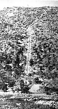
| Figure. 1 View of Reservoir Mountain, Pipe Line and Power House Site of San Joaquin Electric Company. |
THE CANAL AND RESERVOIR.
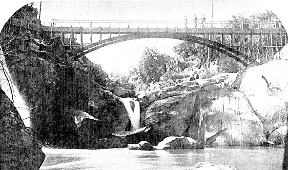
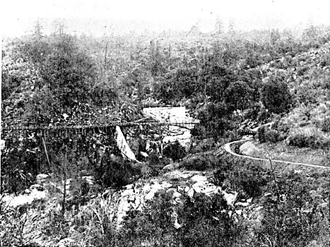
Nature appears to have foreseen the necessities which have led to the development of water powers and their utilization by tile means or electricity, and the band of man could not have executed a more favorable plan than that upon which the water power of the San Joaquin Electric Company has been developed. High in the Sierras and well within the winter snow line, the North Fork of the San Joaquin River makes its precipitous descent to the valleys below. Until well in the summer, each valley adds its quota of water to the stream, but only the waters from the larger canyons have perennial flow. Of these, the North Fork and the South Branch of the North Fork of the San Joaquin River, were selected as head waters. No dam or structure of any sort other than simple fluming marks the diversion points, the flumes being simply extended into the banks at the side of the streams, or are well bolted to bedrock, and continue thence to their confluence shown in Figures 2 and 3. The canal thus formed is about seven miles in length, of which 3,000 feet is of wood flume, and the remainder is ditching. Waste gates have been placed in the canal at every 4,000 feet, and the canal has a capacity of 70 cubic feet of water per second.
| |||
| Figure. 2 Arch Flume Structure Over the North Fork of the San Joaquin River, Showing Confluence of the Diversion Flume Into the Main Flume. |
| |||
| Figure. 3 Another View of the Confluence of the Diversion Flumes, Showing Site of the North Fork Diversion, A Portion of the Ditch and Flume of the South Branch of the North Fork Diversion and An Overflow Gate in the Main Flume. |
A great portion of the flume has been built on solid rock, forming the bed of the river. The severe freshets that occur during the winter months necessitate the utmost rigidity in securing the flume to the rock. This was done by anchor bolts consisting of heavy iron split at the end for from four to five inches, and into winch steel wedges were started. The bolts, with the wedges started, were then driven into holes that had been drilled into the solid granite, and the spreading thus caused by the wedge rendered the withdrawing of the bolt practically impossible, but greater security was given by filling the holes with Incited lead. So firm has this construction proven that the storms and freshets of the past winter have directed the flume way. The ditch is built throughout in a reddish loam, which settles and packs so that no seepage occurs. A portion of the ditch is shown in Fig. 4.
THE RESERVOIR
An interesting feature in the development of the water power consists in the peculiar topographical formation of the ridge upon which the reservoir has been located. This ridge extends out as a spur from the backbone of the main North Fork Ridge, and is bounded on one side by the North Fork of the San Joaquin and on the other by Fish Creek. It is around this main ridge that the canal is carried, and Reservoir Mountain, as the spur ridge is aptly termed, consists practically of a table land with three sides very precipitous. The location of the reservoir, together with its elevation, is clearly shown in Figure 5. In the background are seen ridges of the main chain of mountains, while in the valley between them and the reservoir runs the San Joaquin River. The area of the reservoir is about eight acres, and it was formed by throwing up an earth embankment to a height of eight or ten feet for a distance of about 500 feet. Its storage capacity is sufficient to operate the transmission plant to full capacity for between five and six days.
| |||
| Figure. 5 Crest of Reservoir Mountain, Showing Reservoir and Flume Leading Thereto. |
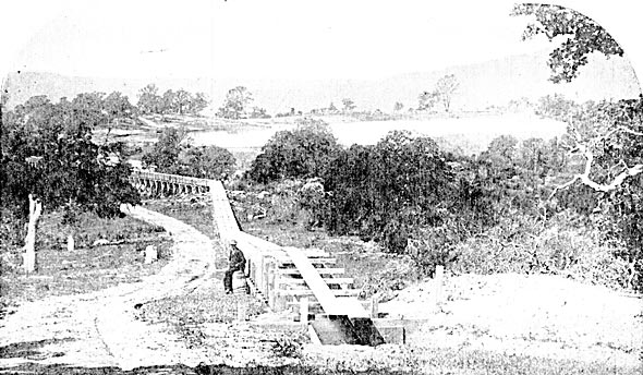
The favorable location of the reservoir can be better understood by reference to Figures 1 and 5, which are really companion photographs. Figure 1 is made from a photograph taken well down on the mountain side shown in Figure 15 and the reservoir is directly over the crest at the top of the mountain in Figure 1. Water may be supplied to the pipe line either from the reservoir or direct from the flume, an additional 800 feet of which has been constructed to sub-serve this purpose. The head of the pipe line, together with bifurcating gates, pressure box and air stand pipe, is shown in Figure 6.
| |||
| Figure. 6 Bifurcating Gates, Pressure Box and Air Standpipe at the Head of the Pipe Line. |
The pipe line consists of practically three sections, according to the variety of pipe used. The first 1820 feet is of riveted pipe, 24 inches in diameter, the first 960 feet of which is of No. 12 steel, and the remainder is of one-fourth inch steel. Then follows the second section, consisting of 400 feet of standard converse lock-joint welded pipe 20 inches in diameter and having lead joints. The last section, which is also 1,800 feet in length and has a diameter of 20 inches, consists of lap-welded pipe, with flange joints made tight with rubber packing. The entire length of the pipe line to the receiver is, therefore, 4,020 feet. The first section was built by the Risdon Locomotive Works, and pipe for the remaining sections was furnished by the Dunham, Carrigan & Hayden Company, and was made by the National Tube Works of McKeesport, Pa.
As stated, water may be conveyed to the pipe line either from the reservoir or the canal direct and to prevent litter from being carried down the line, the openings of the pipe lines leading to the pressure box have been provided with bell mouths, each 6 feet in diameter across the mouth and covered by a massive screen containing 1,800 one-half inch holes. From the pressure box a 12-inch stand pipe, with suitable valves, extends to a point above the level of the reservoir. The bifurcating gates, as well as all other gates and relief valves, are of Risdon make.
Much difficulty was experienced from unappreciated causes in the erection of the pipe line, and being about 4,000 feet in length and running over different geological formations various expedients had to be resorted to secure stability. At some portions the pipe line has been buried to a depth of from five to eight feet in the soil. Elsewhere it is supported on short bridgings but the general construction consists of bolting the pipe firmly to the massive granite bed-rock. Stay rods, or holding-back bolts, arc not used, but instead the pipe is held down in the manner above described for holding down the flume. With the pipe line, however, the split bolts are sulphured into the granite to a depth of from five feet to seven feet, and to the bolts are screwed semi-circular, flat iron bands, 2-1/2 inches by 5/8 ths inch in size, placed on top of the pipe.
The pipe line was built from the ends towards the center and as the time for closing in the gap approached a new obstacle appeared. Early in the morning, before sunrise, the gap between the pipe ends, and which is best termed "the cold gap," was 7 feet 8 inches. In the afternoon, and about sunset, this gap would close to exactly 7 feet, giving "the hot gap" due to the expansion of the pipe by the heat of the sun.
Section 1, consisting of 24-inch riveted pipe, was built first, the construction being begun at the lower terminus and laid from the bottom upward, the pipe being held in place with heavy timbers known, by boiler-makers as "dead men." The lap welded or 20-inch pipe was laid from the receiver upwards, leaving a gap between the reducer piece or taper joint on the riveted pipe and the last bell of the converse lock joint pipe. Early in the morning, before sunrise, this gap, best termed "the cold gap," was 7 feet 8 inches. In the afternoon, and about sunset, the gap would close to exactly 7 feet, giving "the hot gap" due to the expansion of the pipe by the heat of the sun. The closing of the gap was- thus resolved into the problem of finding the minimum temperature of the pipe, then closing the opening and filling the pipe with water before sunrise. All tools and materials were gotten ready, and at 2:30 a. m. the gap measurement was taken, a piece of lap welded tubing was cut to fit and then driven in place tightly. A loose bell was used and the rib chipped out so that it slipped freely over the edge of the pipe at the point of splicing, and when-the connecting piece was in place and slipped over, the joint was filled with lead on both sides and caulked, thus completing the pipe.
One is not to be disappointed in the natural expectation that the installation and operation of a pipe line of this character would be attended by many peculiarities if not phenomina entirely new. Operated as it is, under a head of 1,411 feet, and having imposed upon it the trying conditions incident to the control of hydrostatic pressure of 60!) pounds per square inch, the requirement that electric generators shall be operated at a practically uniform speed necessitates the exercise of the greatest ingenuity in the design of water wheel governors and the San Joaquin pipe line, being strictly the pioneer in this direction, has had imposed upon it both the use and abuse that would naturally fall upon the first undertaking of the kind. It is with a view that the difficulties experienced may be obviated in future installations of this character that considerable space is given to them.
Students of acoustics may care to know that to halloo into the mouth of the empty pipe line invariably causes seven distinct echoes. The normal flow of water in the pipe is at the rate of 1-1/2 feet per second, and the present plant in the station, when operated to full capacity, does not consume sufficient water to enable the determination of the friction head. The velocity of the water from the 1-1/8 inch nozzles used is something over 9,200 feet per minute, and nothing is more impressive of the terrific energy of water at this head than a recital of some of the difficulties that have been encountered in controlling it. The general features of construction that have become well established by the erection of many plants operating under heads of from 500 to 600 feet or less were first carried out in this installation, but subsequent experiences compelled their abandonment and the design of special features to satisfy the conditions found to exist. In the wheel pit for instance, mid in the tail race all masonry construction is of the most solid character. The wheel pit was carefully dosed over by heavy planking, and upon turning on the water it refused to go out the tail race and along the bottom of the ditch, but instead rolled up the sides of the pit or followed up the water wheels to the plank covering and along the under side of the planks it rushed madly out, almost horizontally, for a distance of sixty feet, where it struck a great granite boulder, and was lost in spray.
The jets strike the wheels at an angle of 45 degrees from the horizontal, and, the nozzles being deflecting, the impact water strikes the bottom of the wheel pit with terrific fury. After two days operation the water had cut under the concrete and into the seams of the bedrock, coming out in the power house and outside of it. To obviate this a 14-inch steel pipe, 4 feet in length and having a heavy steel plate across the lower end, was let into the bottom of the wheel pit in line with the jet, the idea being that the pipe would fill with water and form a water cushion to take up the blow. Instead of doing this, however, it merely reversed the direction of the stream, and the waste water landed on top of the power house, not taking the usual course. Then some one recommended that the wheel pit be dammed up so as to carry two or three feet of water, which would tend to prevent the emptying of the cushion pipe, with the only difference from the preceding experiment being that in addition to the waste water the water impounded in the wheel pit was also landed on the station roof and thereabout. Nevertheless the "water cushion" pipe was allowed to remain, but it was filled level full with concrete and the bottom was completely floored over with 3-inch planking which was sheathed for 3 feet about the nozzle with 3/8-inch steel plates. At that time the water was slightly muddy and considerable granite sand had been washed into the tail race and as a result in less than three days a 1 inch jet which had been left in, had worn its way through the steel plate and the 3-inch planking, and was at work upon the demolition of its old enemy, concrete and masonry. The heroic method of feeding a fresh cast-iron plate 1-1/2 inches in thickness to it as often as necessary has now been resorted to as the best solution of the problem.
SOME EXPERIENCES IN HYDRAULICS.
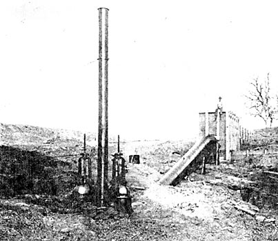
The question of wheel regulation at once constitutes the most serious encountered in the whole installation and the method now being tried consists in tapping the main pipe line at a point sufficient to give a head of 200 pounds at the power house. At this point an auxiliary tank with an independent six-inch pipe is to be erected, and from the constant, or unvarying water pressure thus realized, the constant speed Pelton wheels for operating the governors will be driven. In addition to the Pelton differential deflecting nozzle governer, other governors are to be tried, among which will be the Lighthipe electric governor, soon to be described in these columns. The weight of the water contained in the pipe is approximately 317 tons. The end thrust thrown upon the receiver is about 93 tons, to withstand which four 2-1/2-inch stay bolts solidly bolted to the receiver have been imbedded in beveled abutments, as shown in Figure 7. The receiver itself is 57 feet in length, with a diameter of 30 inches; it is constructed of 3/4-inch flange steel, with a tensile strength of 60,000 pounds and an elastic limit of 30,000 pounds. External and internal butt straps are placed thereon in five-foot courses. It is riveted throughout with 1-inch rivets and the stay bulls for withstanding the end thrust are welded to ¾-inch boiler plates, 10 inches in width, that are in turn riveted to the shell of the receiver. The receiver carries two relief valves, and all mountings are of phosphor-bronze, the nozzle saddles being of cast steel. Before leaving the Risdon Iron Works, where it was built, the receiver was tested to 800 pounds hydraulic pressure which was considered noteworthy; but since its installation it has been subjected to a far greater strain without injury, as will appear shortly.
| |||
| Figure. 7. Power House of the San Joaquin Electric Company, Showing Receiver and Mode of Withstanding the End Thrust of the Pipe Line. |
It did not take long after water had been run into the pipe to demonstrate that while water at a head of from five to six hundred feet may be considered a liquid, yet at a head of 1,400 feet it becomes a solid with the strength of the hardest steel. The gates and relief valves ordinarily used were placed upon the equipment. The relief valves in particular had, up to that time, been considered perfection, and the balanced internal pressures were so thoroughly worked out as led to the belief that they would operate satisfactorily under any pressure, but the vital point of the friction which ensues from the contact of metal with metal when under high pressure was under estimated, and as a consequence the relief valves are practically inoperative. It is the belief of the engineer in charge that at high pressures water must be relieved by something cumulative. The use of compressed air is impracticable, because of the fact that the air will be forced into the water and the practice finally adopted for protecting the equipment from water hammer, consists in the adoption of gates for controlling the rate of opening and closing, rather than in the use of relief valves.
At the power house the gates are controlled by hydraulic rams actuated by water taken from the pipe line. As originally installed, any one of these rams opened the gate so as to cause a fluctuation of 170 pounds from the normal, and here is noted a phenomena due to the elasticity of the pipe. With the original equipment upon opening the gate the pressure would drop 90 pounds below normal, then rise to about 80 pounds above normal; then drop in wave motion to say 75 pounds below normal and so continue for from 20 to 30 seconds, until the normal pressure was reached. Upon closing the gates precisely the same conditions would arise with the exception that the initial change would be 90 pounds above normal. The acts of opening or closing the gates are therefore identical, so for as water shock is concerned and so perceptible is this fluctuation or "breathing" of the pipe, in the first or wrought steel section of the pipe line, that upon sitting astride of it one can feel its "breathing" as though it were a giant reptile.
| |||
| Figure. 8 Pelton Water Wheel Mountings, Showing Fly Wheel, Exciter Wheel and Lower End of the Receiver. |
The fluctuation of 170 pounds was altogether too great to admit of satisfactory operation and accordingly it was determined to reduce the speed of the ram in opening or closing the gates by reducing the size of the exhaust outlets in front of the piston. Accordingly the diameter of these orifices (one at each end) were reduced to 1/8 of an inch each, which reduced the water shock to 50 pounds above and below normal. But 3-32-inch orifices were eventually adopted which increased the time of opening or closing the gates to 30 seconds and reduced the water shock to 30 pounds above and below normal. These devices were entirely automatic in their action, giving absolute satisfaction in the handling of the head.
The experience with this pipe line has, as stated, made it plain that when water is under high pressure in a large column it becomes the equivalent of a solid bar of equal weight, standing on end, and it is from handling this column of water, 4,000 feet in length, weighing 317 tons and exerting a pressure of 609 pounds, that the conclusion is reached that this column of water must be handled in exactly a similar manner as would be devised for handling a solid column of like dimensions, namely: time must be an element in starting and stopping the column in order to overcome the "Water shock," or combined force of the momentum force of the water itself, and the expansion and contraction of the containing vessel. With this idea of "time," as a simple thought, the volume should be set in motion and brought to rest by a device that would be the equivalent of withdrawing an inclined plane, the taper of which is represented in the time required in getting the column in "notion, or in other words, to handle water successfully under extremely high heads there is only one true and safe way, and that is by means of screw gates, as by this means the column of water can only be started or stopped very slowly. If this method is employed water shock and at the same time relief valves for taking care of the same, will be an unnecessary problem.
Under the head of relief valves for very high pressures the conclusion reached is that any method whereby water is discharged is more liable to constant increase of water than otherwise, as it has a tendency to increase the velocity of the water column, which in itself is the primary cause of water shock, and hence the conclusion is that devices for handling high heads should be so arranged as to make water shock absolutely impossible, however careless operatives may be.
| |||
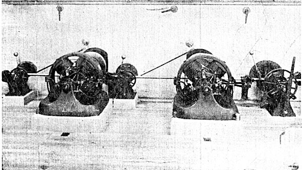
| Figure. 9 the Completed Receiver and Pelton Water Wheel Plant. |
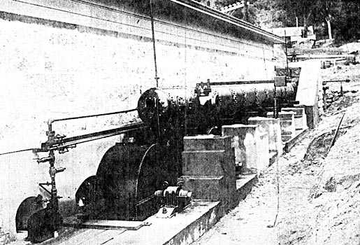
As shown in Figure 9 the receiver is mounted alongside the power house and directly beneath it are the Pelton water wheels constituting the power plant. Independent single jet Pelton wheels are furnished for each generator and exciter, and two smaller wheels operate a line shafting at constant speed for driving the governor mechanisms. In the main wheels the Pelton wheels have an outside diameter of 57 inches and each wheel carries 27 buckets bolted to its periphery. The speed is 600 revolutions per minute. On the same shaft with the main wheel is seen the 6000 pound fly wheel 60 inches in diameter with which each wheel is provided. On the periphery of the fly wheel is shrunk a heavy cast steel band two inches thick to prevent its disruption at high speed from centrifugal force. As mass available for fly wheel effects aggregates 13,000 pounds. The diverting nozzle mode of regulation is used but it is probable that the conditions prevailing will necessitate the devising of special regulating apparatus to meet the conditions imposed.
| |||
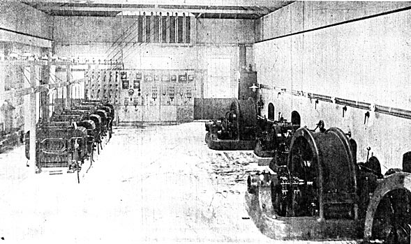
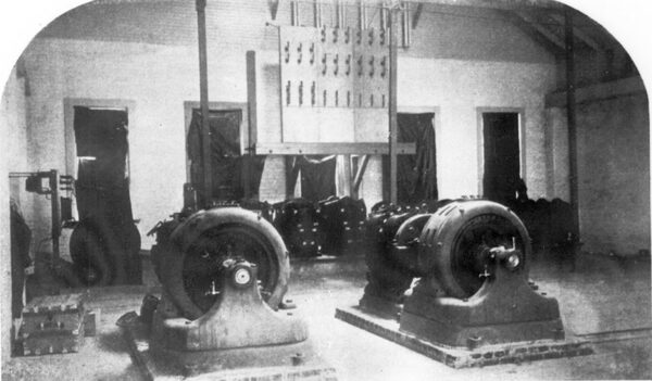
| Figure. 10 General View of the Interior of the Power House. |
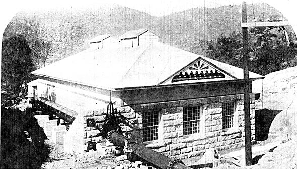
THE POWER HOUSE.
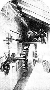
The power house is a model of central station architecture; it is 76 feet long by 36 feet in width, and as appears in Figure 7, is of granite. Within it are three 340 kilowatt multipolar General Electric 3-phase generators delivering current at 700 volts and 60 cycles per second to the low potential switchboard shown in Figure 14, whence it is carried to the bank of nine 125 kilowatt transformers, delivering 3-phase current to the line at 11,000 volts through the high potential switchboard. In addition the station carries two 12-1/2 kw, multipolar exciters, each being of sufficient capacity for the operation of the entire plant. The method of high potential wiring used in the power house is shown in detail in Figure 13.
|
| |||
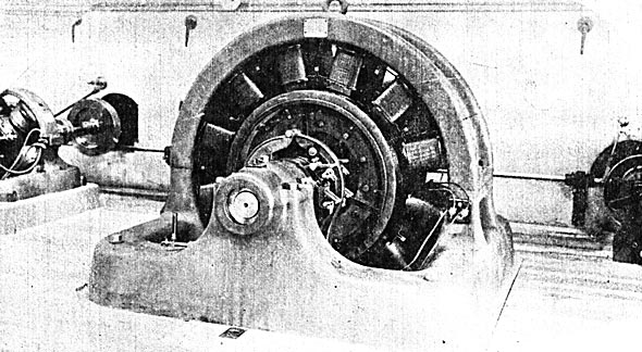
| Figures 11 and 12 Showing Exciters and Constant Speed Regulator Shafning, and One of the 340 K. W. Generators, Respectively. |
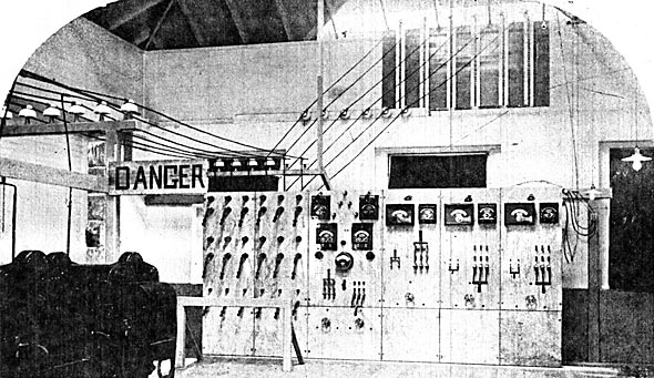
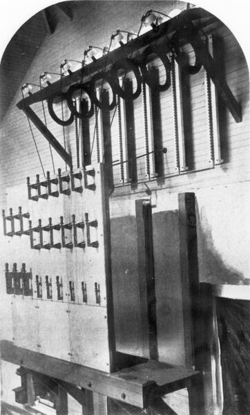
The power house and sub-station are protected by Bell lightning arresters and choke coils, the detail of which are best shown in Figure 18. Each transmission line upon entering the station is taken through a choke coil consisting of 150 feet of the same size of wire as used in the line. In the present instance, No. 3 B. & S. copper wire covered with weather proof insulation is coiled into a ring fifteen inches in diameter, the whole ring then being well taped. From the coil the high potential circuit is carried to the high potential switchboard and thence to the step-down transformers. At ordinary periodicities, such as 60 cycles per second as used in the Fresno plant, the self-induction of these rings is inappreciable, but at the enormous frequencies of a lightning strike the coils prove effective in protecting the apparatus beyond them and in forcing the lightning to take the path to earth provided through the lightning arresters. Each of the transmission lines is provided with a lightning arrester as shown and these consist of 40 non-arcing metal cylinders screwed to a base and hence removable, the surface of each being separated 1-32 of an inch from that of the adjoining cylinder. The ground discharge from the bottom of the arrester is carried to earth by a copper ribbon one inch in width by 1-32 of an inch in thickness. Similar rings with suitable arresters are also placed on the 1000 and 2000-volt circuits the sub-station.
| |||
| Figure. 13 Generator and High Potential Switchboards at the Power House, Showing Method of High Potential Wiring and Lightning Arresters. |
THE POLE LINE.
The entire pole line, whether on the mountains or over plains-is constructed of square sawed redwood poles, 12 by 12 at the butt and 6 by 6 at the top, the length varying from 35 feet to 40 feet according to locality. On the plains the poles are set 120 feet apart, while on the mountains the separation varies according to the contour, but approximates 100 feet. Standard six-pin seven-foot cross arms are used. These are placed 20-3/4 inches apart and the pole lines for the transmission proper carry two such cross arms for the transmission circuits and one additional 48-inch cross arm for the telephone service, the latter being 62-1/4 inches below the lower high tension cross arm. Certain portions of the pole line are equipped with a third cross aria for carrying the vineyard circuits of the company.
| |||
| Figure 14 A Portion of the Mountain Pole Line, With the Power House Site, Pipe Line and Reservoir Mountain in the Background. |
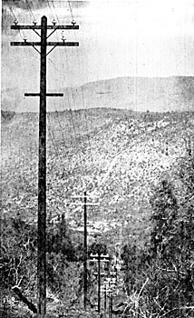
The poles were hauled and erected by the San Joaquin Electric Co. and the task was beset with difficulties owing to the mountainous country and the frequent blasting necessary in digging holes. Throughout the timbered portions of the route a 20-foot clearance has been cut, as have all trees that could by any possibility fall across flue circuit. In addition to this clearing the San Joaquin Company constructed a wagon road 4-1/2 miles long and a bridge having a 100 foot span and 340 feet of approaches.
| |||
| Figure 15 View of the Pole Line Near Fresno City. |
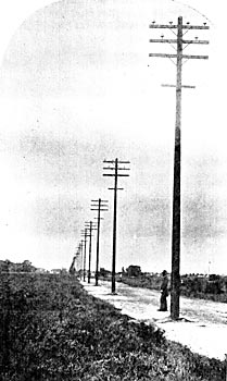
The transmission circuits consist of two 3-phase 3-wire sets which may be used independently or together as desired. All wires are of No. 3, B & S. soft-drawn copper. These two sets are divided by flue pole, and the top cross arm supports two wires of each set, the third wire being immediately below. The lines are arranged so as to form an equilateral triangle having twenty-four inches on a side and the main line is transposed every poles, or approximately every mile. Standard triple petticoat porcelain insulators are used and the method of tying is peculiar. A No. 8 soft copper tie wire is used. This is about 20 inches in length and in placing the line wire in the top groove the tie wire is placed with it and its ends are carried around the insulator groove in the same direction, each end making a complete circle before being wrapped. The wires were strung by a line corps of the General Electric Company, under Mr. B. O. Boswell, Superintendent of Line Construction, and although the line construction did not begin until January 13th last, it was finished on February 23d, twenty-three men being employed in the work. Only one trouble has vet occurred to the line and that was due to a defective insulator which caused a short circuit equivalent to a load of 6000 lamps at Fresno. The circuit was at once cut out, the entire load was thrown upon the other set of lines until the following morning, when the trouble was found and remedied.
The results obtained from the telephone circuit carried over this pole line are truly marvelous. Hunning's dust transmitters of a type that do not infringe the patents of the American Bell Telephone Company are used over a circuit of No. 14 hard drawn copper wire supported by porcelain knobs. The telephone circuit is transposed at every fifth pole through the use of Locke's transposition insulator and the line is absolutely quiet despite the facts that its length is 34-1/2 miles and that the initial potential is 11,000 volts.
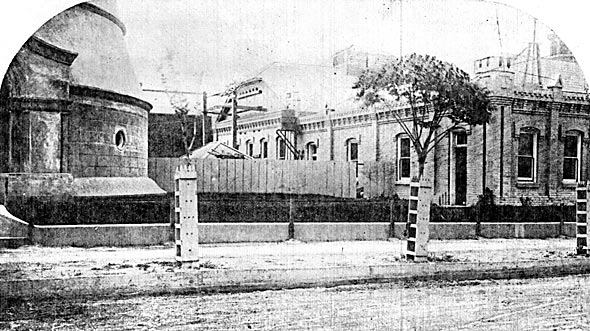
THE SUB-STATION.
The transmission lines enter the sub-station in Fresno in the manner clearly shown in Figure 18. The high potential switchboard there shown is not accessible and the switches are thrown by the use of a long bamboo pole with a ring on flue end. It is difficult to measure the length are drawn out on throwing switches because irradiation, even at full load it does not appear to be in excess of one-half of an inch. The high potential switchboard affords the means for throwing any of the various types of step-down transformers on to either one or both of the two sets of transmission lines. These step-down transformers are all of the air-blast type and are divided into three sets, each designed for a separate purpose. Three 125 k. w. transformers with secondaries wound "Y" deliver current at 115 volts to the 4-wire commercial incandescent circuits. The second set consisting of three 75 kilowatt transformers with secondaries wound "delta," deliver current at 1000 volts for operating power circuits through the use of induction motors. The third set, consisting of three 40 kilowatt transformers, also wound "delta," delivers current at 3000 volts for the vineyard and other outlying districts. A 5 kilowatt induction motor drives a Sturtevant blower for the cooling of the transformers and the fact that this motor is belted to the blower forms the only inharmonious feature in the equipment of the sub-station.
| |||
| Figure 16 Rear View of the Sub-Station in Fresno, Showing Mode of Entering High Potential Circuits. |
From these transformers the current is carried to the low potential board which is not fully completed at the present time. This board was designed by Mr. Ernest I. Dyer of the General Electric Company and consists of ten panels all but one of which are now in operation. Of these, five are for controlling the low potential incandescent service; one panel controls the 3000-volt vineyard circuit; one controls the Chinatown 1000-volt incandescent service; two panels control the 1000-volt mains for the outlying residence lighting; and the last panel controls the induction motors driving the Brush arc light machines shown in Figure 19. Each of these are light sits consists of n three phase induction motor direct coupled to an 80 lamp, 2000 candle power, Brush arc lighting dynamo, run at 700 revolutions per minute. A special switchboard for the arc lighting service and which is not shown in the illustrations is of one panel carrying six circuits and provided with two Weston ammeters and four type "A" Thomson-Houston lightning arresters, together with the usual accompaniment of spring jacks and the differential equipment of the new regulator for Brush "Z" type dynamos. The 1000-volt power service is taken direct from the transformer to the line and the Chinatown service is rendered through a special 3000-volt transmission to Chinatown, where step-down transformers reduce the potential to 115 volts for distribution on the four-wire system.
The entire business section of the town has been wired up uniformly with the four-wire system. No. 0000 B. & S. bare copper Wires are used almost exclusively as feeders and are so arranged that wires to the south and west of pole lines are the neutral wires and those adjacent thereto are the "A," "B," "C" wires respectively in the order of their sequence. This arrangement is due to Mr. J. N. Smith, Chief Electrician of the San Joaquin Electric Company.
The regulation of all circuits, whether for power or incandescent service is effected through potential regulators introduced into each outgoing circuit and by means of which the voltage is regulated at centers or distribution.
RATES OF SERVICE.
A surprising feature in connection with the San Joaquin Electric Company is the remarkably low rate at which electric service is rendered. The company has secured the municipal lighting contract for lighting the city of Fresno with 2000 c. p. are lamps at the rate of $6.45 per lamp per month, all night and every night. Electric power is delivered approximately at the rate of $64.00 per h. p. per year 24-hour service, and incandescent service is rendered by Meter rates or flat rates. The rate for meter service is 15 cents per kilowatt per hour, with discounts varying from 5 per cent to 25 per cent, according to consumption. In residence lighting flat rates prevail exclusively and the novel system has been inaugurated of charging for service according to the location of the lamp at the following rates per month.
Sitting room, 30 cents per 16 c. p. lamp per month.
Halls, dining. room, or kitchens, 25 cents per 16 c. p. lamp per month.
Parlors, pantries, and barns, 15 cents per lamp per month.
Bed and bath rooms, cellar, garret, 10 cents per lamp per month.
The very favorable rates which have been established by the San Joaquin Electric Company for power service have already brought it several large contracts, principally among which is that of the Sperry Flour Mills, which is being operated by a 150 kilowatt synchronous motor running at 600 revolutions per minute. The city water works will also be run by electric power and a 75 kilowatt induction motor belted to a Root rotary pump having a capacity of 3,000,000 gallons daily has been installed. This latter equipment will displace a 4,000,000 gallon triple expansion Holly steam pump now used. At the present time the company is burning about 1600 incandescent lamps and has contracts secured for 1,100 additional lamps. It is also prepared to enter upon its street lighting contract as soon as its pole lines have been completed, and is ready to deliver power as fast as motors are received.
PROMOTERS OF THE ENTERPRISE.
The conception of the plant of the San Joaquin Electric Company is due to Mr. T. S. Eastwood, a Civil Engineer of Fresno, who from his familiarity with the mountainous regions in the Sierras, back of Fresno, had long been impressed with the magnitude of the water power there available, and as soon as the feasibility of electric transmission over long distances had been commercially assured, he began the organization of a company for the purpose of developing water power and transmitting its energy to Fresno. Fresno offered a particularly favorable field for the introduction of electric light and power, because of the high price of fuel and the fact that the influences of the lighting interests theretofore existing had been bent in the direction of restricting the means of lighting to the use of gas and arc lamps. As a result of Mr. Eastwood's efforts, Mr. J. J. Seymour, President of the Fresno Water Company, became interested in the enterprise and they soon organized the San Joaquin Electric Company. This was accomplished on April 2nd, 1895, since which date the scheme has been perfected and the plant is now practically completed. It would be difficult to find a proposition of such magnitude that has been handled with greater celerity, and the installation stands a fitting monument to the genius and energy of California promoters. While the business detail has been handled mainly by Mr. Seymour, as President and Manager Mr. Eastwood has had charge of all engineering and superintendence, and his ideas arc impressed so thoroughly throughout the various branches of the work that he can not bid have won for himself lasting fame in the development and control of high heads of water.
| |||
| Figure 17High Potential Switchboard at Sub-Station, Showing Lightning Arresters and Choke Coils. |
| |||
| Figure 18An Interior View of the Sub-Station, Showing High Potential Switchboard, Step-Down Transformers, Blowers, Induction Motors and Arc Dynamos. |
The electrical apparatus used throughout is the three-phase type of the General Electric Company, and the entire installation was placed under the supervision of Mr. J. A. Lighthipe, Chief Engineer of the Pacific Coast office of the General Electric Company, and who was assisted by Mr. C. O. Schaefer, Superintendent of Construction of the sub-station; Mr. A. C. Jewett, Superintendent of Construction of the power house, and Mr. B. O. Boswell, Superintendent of Line Construction.
This describes the electric transmission plant which exceeds all others in the world in the combined points of size or distance of transmission, and height of head water used. It has an unfailing supply of 50,000 h. p. of water available.
