[Trade Journal]
Publication: Electrical Review
New York, NY, United States
vol. 78, no. 4, p. 135-138, col. 1-2
Suspension Type of Transmission Line Insulators
Eleventh of a Series of Articles Giving a Review of the Electric Power SituationGrading Suspension InsulatorsStatic Shields and Arcing HornsDesign and Construction of Insulator Units
By ALFRED STILL
The suspension type of insulator was first used when line pressures of 100,000 volts were introduced. Since 1907 it has superseded the pin type of insulator for pressures above 60,000 volts and even less. With the suspension type of insulator the conductor is hung below the point of support (which is usually grounded) at the end of a string of insulator units connected to one another by metal links. The potential difference which will cause a flashover or breakdown on such a series of insulators will not be in direct proportion to the number of insulators in the string. This is due to the unequal distribution of the potential differences, which is again a question of relative capacities. The design of the individual units may appear to be good, and yet a string of such insulators, if they are not specially designed to fulfill certain requirements, may give surprisingly unsatisfactory results. A factor of importance is the ratio of the mutual capacity to the capacity to ground, which determines the potential distribution.
The distribution of the potential drop on a string of suspension insulators is easily calculated if certain assumptions are made with a view to simplifying the work. If symbols are used to denote the various voltages and currents, the formulas become somewhat complicated in appearance although actually simple in application. A clear explanation of the voltage distribution on the string of suspension units has been given by F. W. Peek, Jr.
The fact that the ratio of the mutual capacity to the capacity between the suspension link and ground is an important factor in determining the distribution of potential over the insulator string suggests the importance not only of the shape and surface area of the metal fixtures on the individual insulators but also the length of the connecting link and the spacing between insulators.
GRADING INSULATORS AND USE OF STATIC SHIELDS.
In this country it is common practice to use the same size and type of disk throughout a string of suspension units, but this necessarily leads to a greater potential difference across those near to the high-tension line than across those near to the (grounded) point of suspension. In connection with tests on strings of insulators, such as those recently conducted by Profs. Harris J. Ryan and Henry H. Henline at Leland Stanford University, the expression "voltage-duty ratio" is used to indicate the ratio between the voltages across two unit insulators in a string of suspension insulators. With a string built up of 15 standard 10-in. suspension discs a voltage-duty ratio as high as seven is possible, and this means that the unit next to the high-voltage conductor is normally subjected to seven times as great a pressure as the unit next to the point of attachment on the tower crossarm. This is unsatisfactory, and a suspension type insulator built up in this manner would be undesirable on a practical transmission line.
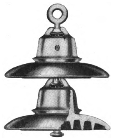 |
| Suspension Insulators Manufactured by Ohio Brass Co. |
The grading of insulators so as to provide for a more uniform distribution of potential throughout the string has been given much more attention in Europe than in this country. In this country we have tried and are proposing to use a metal shield between the lowest unit in the string and the high-tension conductor, and this, by preventing the concentration of the dielectric flux at the point of attachment, has the effect of improving the voltage-duty ratio. A static shield of this nature will usually take the form of a flat disk with well-rounded edges and having a diameter appreciably larger than that of the porcelain disk. An elliptical shield with its major axis in the direction of the line is also effective. Besides serving to reduce the potential difference across the units near the conductor the static shieldin common with arcing horns and ringsalso tends to prevent corona formation over the porcelain surface at the point where the metal caps or links are connected to the porcelain. On a string of ten disks, the provision of a static shield may reduce the potential drop across the first insulator unit by as much as 25 to 40%.
 |
| Arcing Horn for Suspension InsulatorsManufactured by R. Thomas D Sons Co. |
Although maximum voltage-duty ratio as high as seven has been mentioned as possible on a string of 15 units, this ratio would be about 2.5 on a string of ten units, and this could be reduced to below 1.5 by the provision of a static shield of the type above described. A still further improvement could be made by grading the units, i. e., using two or more different sizes or designs in the same string.
NUMBER OF UNITS IN A STRING OF SUSPENSION INSULATORS.
The number of units in a string will depend upon the line voltage and the size or make of unit. Lines operating at 66,000 volts are using strings with any number of units ranging from three to eight. The higher voltage lines will naturally require more units, but owing to the unequal distribution of potential drop along the series the addition of extra units to a long string will have little effect in reducing the potential difference across the first unit. Additional units in excess of the number which appears requisite for the duty demanded of them increase the safety factor of the string because they will take their share of the voltage in the event of the breakdown of other units. On 110,000-volt lines the number of units per string ranges from five to nine. On 130,000-volt lines nine or ten units are used, but as many as 12 units in a series are used at dead-ends on tension towers.
From what has been said concerning the voltage distribution over a string of suspension units it will be understood that when the mutual capacity is small relative to the ground capacity there soon comes a point beyond which it is useless to put more insulators in the string. Short strings of well-designed and properly spaced units will often be more effective and less costly than a longer series of insulators of which the single units may have excellent insulating properties, but may not have been' specially designed for the particular requirements. It is sometimes possible to increase the arc-over voltage of a string of insulators by reducing the distance between consecutive units, a fact that it is difficult to understand unless the importance of the proper capacity distribution has been realized. A well-arranged string of properly designed units, not necessarily similar in shape and size, is less liable to damage by lightning and kindred phenomena than a series of insulators of high voltage-duty ratio.
It is well to bear in mind that an insulator may and does behave differently when subjected to high-frequency charges such as those induced, by lightning disturbances than when the difference of potential is applied at the normal frequency of the transmission line. The distribution of potential. among a number of condensers in series should be independent of frequency, but a high-tension insulator consists of many capacities in series with resistance such as the leakage paths through the body of the material and over the surfaces and the distribution of the total potential drop across a condenser and resistance in series, even if the latter may be considered non-inductive, is not the same at high as at low frequencies. This is one of the reasons why insulators that will flash over rather than puncture on tests conducted at the ordinary line frequency will sometimes fail through puncture during atmospheric electrical disturbances.
Apart from the great advantages from the point of view of insulation which are obtained by suspending the conductor from a string of insulators connected in series, this arrangement, now generally adopted for pressures above 50,000 volts, has the further advantage that the conductor is less liable to be affected by lightning disturbances, since at every point of support the wire is hung below the attachment to the supporting tower, which in almost every instance is a well-grounded steel structure. Another advantage is the comparative flexibility of the attachment, which very considerably diminishes the possibility of crystallization of the conductor material, such as is liable to occur when the wire is rigidly attached to the pin type of insulator. This effect is more noticeable with aluminum than with copper.
DESIGN AND CONSTRUCTION OF SUSPENSION INSULATORS.
A great deal of attention has recently been devoted to the improvement of the suspension type of insulator. The parts of the early designs were cemented solidly together, with the result that the differential expansion of porcelain and metal caused cracking and consequent destruction of the porcelain after being in use for only a few years. That experts in insulator design realize the effects of expansion and other causes leading to rapid deterioration of porcelain insulators is evidenced by the experimental work that has been carried on, and the number of papers published relating to this subject during the last three or four years.
 |
| Thomas Arcing Horn for Use in Connection With Strain Insulators. |
It is proposed to discuss the question of deterioration and failure of insulators in another article. Unquestionably much trouble has arisen through unequal expansion under temperature variations of porcelain, cement and hardware in the usual type of unit in which the metal cap and link are cemented to the porcelain. When trouble was first encountered due to this cause, felt or paper gaskets were placed between the metal cap and the porcelain. In more recent designs these gaskets were removed from the finished product after the cement had set, to avoid trouble due to ionization; but various devices of the nature of elastic washers or packing between metal and porcelain are now used with a view to overcoming this trouble.
Cap and pin type suspension insulators of Westinghouse manufacture are set under steam for the purpose of accelerating the setting action of the cement and of having the setting action take place with the materials expanded. Cement which has passed the required test is sifted through a 1, 16-in. mesh sieve and thoroughly mixed, giving a mortar semi-fluid in consistency. The cap is placed, clevis down, in a rack made for this purpose. The cushioning material is placed in position and enough cement poured into the cap so that when the insulator is pressed into position some of the cement flows over the edge of the cap. The cushioning material for the pin is then placed in position, Cement added and the pin inserted. The pin is worked to drive off the trapped air, settle the cement and obtain the proper alignment. The assembled insulator is then picked up by the cap and transferred to the steam chamber, being placed in the inverted position on a rack. The air in the steam chamber while the insulators are being placed is kept moist by throwing water on the floor. After filling, the doors of the chamber are closed and the steam turned on.
In the Jeffery-Dewitt suspension insulator unit the troubles due to unequal expansion of the metal cap cemented to the porcelain are overcome by employing a flexible spider fastened to the porcelain by means of an alloy having sensibly the same coefficient of cubical expansion as the porcelain, thereby eliminating the temperature effects in the operation of the insulator. The makers of this insulator have no hesitation in submitting it to the following test: Immerse in boiling water for five minutes; remove and plunge immediately into iced water for five minutes; then back into the boiling water, and so on, repeating the process as often as desired.
ADVANTAGES OF THICK PORCELAIN IN SUSPENSION INSULATORS.
In this, as in other modern designs of line insulator, there is seen a tendency to thicken the porcelain. Improved methods of manufacture permit of reliable porcelain being produced of a thickness much in excess of what was used in the earlier insulators.
A low flashover voltage will not always protect an insulator from puncture under abnormal conditions. It is found that the transient voltages which are frequently encountered on transmission systems have a certain time lag in regard to the flashover. Indeed, an insulator which under the usual test conditions has a dry flashover of 100,000 volts may be subjected momentarily to more than 150,000 volts without flashover, this abnormal voltage being a combination of the line voltage of normal frequency and highly damped transient impulses which may be the result of switching operations. A puncture voltage of two and one-half to three times the dry flashover voltage is therefore desirable in order to provide a reasonable factor of safety. Experimental research seems to indicate that the minimum thickness between the electrodes of a suspension-type unit should if possible be of the order of 2.25 ins.
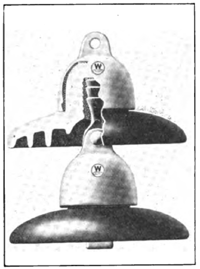 |
| Suspension Insulator Made by Westinghouse Electric & Manufacturing Co. |
In order to fulfill this requirement the Jeffery-Dewitt Co. has produced an exceptionally rugged design of insulator of great mechanical strength capable of withstanding a pull of 9000 to 10,000 lbs.
It is obvious from what has already been said about the concentration of dielectric flux causing a dangerously high potential gradient in the neighborhood of the points where the metal is attached to the porcelain that a large distance between electrodes (i. e., an increased thickness of porcelain), by reducing the dielectric flux density, will tend to keep the potential gradient well below the critical or disruptive value. As a matter of general interest the following figures furnished to the writer by Mr. Peaslee, and representing the results of tests made on a string of five J-D suspension units, are reproduced here. They show how the voltage is distributed between the units connected across 110,000 volts, and how the change in the capacities of the condensers in series alters this distribution when the insulators are wet. The top figures give the potential drop across the unit nearest the tower, while the bottom figures refer to the unit nearest to the high-voltage line.
The maximum voltage-duty ratio is seen to be 1.91 under dry conditions, and only 1.41 when the porcelain is wet, the unit with the lowest voltage across it being in both cases the second from the point of attachment to the crossarm.
A design of insulator with loose-fitting partsthat is to say, in which the metal dues not grip the porcelain through the medium of a thin layer of cementis less liable to suffer injury through unequal expansion due to temperature changes than the more common design in which cement is used.
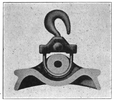 |
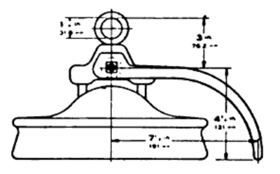
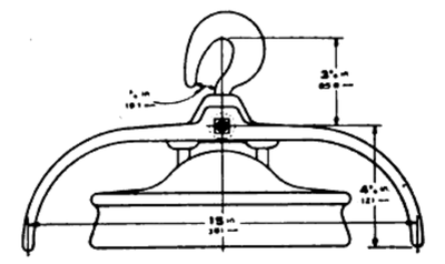
| Cross-Section of Porcelain Member of Thomas Insulator, With Hook. Clovis and Soft Copper Link. |
The link type of unit constructed as shown in the accompanying illustrations was originated by Edward W. Hewlett more than ten years ago. It is now manufactured by the R. Thomas & Sons Co., which has devoted the last three years to the development of suitable hardware fittings which were not entirely satisfactory in the earlier designs.
The advantages claimed for this type of insulator are: (1) The porcelain is thrown in absolute compression, having no side pull nor lengthy porcelain walls in tension; (2) the entire surface of the insulator is thoroughly glazed; (3) the flexibility of parts does not cause concentrated stresses at any particular point, but produces an even distribution of the load; (4) units may be assembled and strings made up in the field as easily as at the factory; (5) the ultimate cost is greatly 'reduced on account of longer life of the insulator and the salvaging or the re-using of connecting parts.
| |||
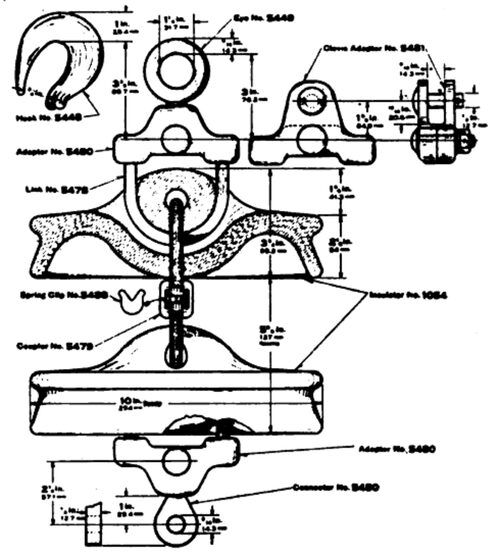
| Illustration Showing Adaptability of Thomas Link-Type Suspension Insulator. |
The suspension type of insulator appears to be the only one suitable for use on the high-voltage lines at present in operation and for the still higher voltage lines which will be erected in the near future. Although porcelainfor reasons which will be further discussed in a following articlecannot be said to be an ideal material for insulators on overhead lines, yet it seems to be the only material at present available on the higher voltages. It is therefore safe to predict that porcelain will be used for many years to come, and moreover that satisfactory insulators will shortly be available for use on 220,000-volt transmission lines. There is no denying that the insulator is a weak point in the power transmission system, but what can be done now on 110,000 and 150,000-volt lines can certainly be done with the same type of insulator on 220,000-volt lines.
| |||
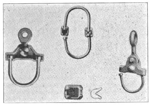
| Clevis and Soft Copper Link Used With Thomas Suspension Insulators. |
It is merely necessary to see that reliable units are used and that these are suitably graded or provided with a static shield so that excessive corona will not be present on the units near the high-tension conductor, and the uneven distribution of potential drop across the string of units will be largely corrected.
It is probable that there will be fewer troubles due to arc-overs caused by lightning or switching operations on the proposed higher voltage lines than on the transmission systems at present operating between 110,000 and 150,000 volts.
