[Trade Journal]
Publication: Chemical and Metallurgical Engineering
New York, NY, United States
vol. 26, no. 10, p. 438-442, col. 1-2
Electrical Porcelain Manufacture
Description of the Plant and Operations of R. Thomas & Sons at East Liverpool, Ohio Production of Ware for High- and Low-Voltage UsesRaw Glazes Employed-Body Similar to Chemical Stoneware-Ceramic Control
BY CHESTER H. JONES
THE 12-kiln plant of the R. Thomas & Sons, manufacturers of electrical porcelains, is well located in East Liverpool, Ohio, for while the ultimate product and markets are different from tableware, the operations in the plant are essentially those belonging to the white ware pottery. The labor market is also best at this point. The plant produces a general line of insulators for low- and high-voltage electrical construction, while the 10-kiln plant at Lisbon, Ohio, is devoted to the manufacture of the patented Hewlett insulator. The Lisbon plant was originally built to manufacture tableware.
R. Thomas, together with his son, the late George W. Thomas, organized the present company in 1873, building the first plant in East Liverpool. - It was the first firm in the United States established for making high-voltage porcelains. Low-voltage porcelains are made by the dry process, where the dried cake from the filter press is ground to powder and compressed in heavy molding machines. High-voltage porcelains follow the method of molding the plastic clay employed in chinaware plants.
| |||
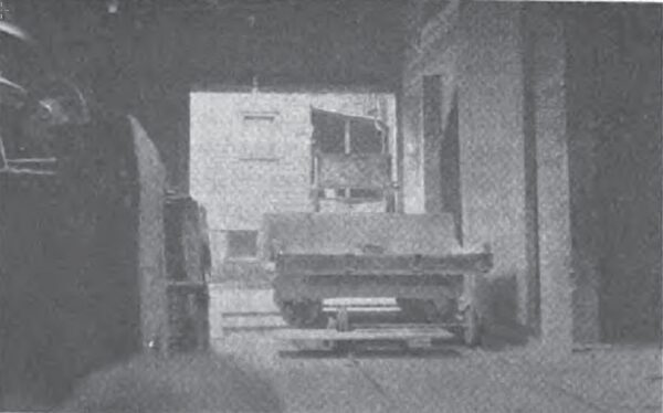
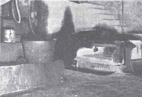
| Fig. 1 Transfer Scales |
STORAGE AND BLUNGER HOUSE
The raw materials used are kaolin or English china clay, English ball clay, flint or ground silica, feldspar, barium carbonate, magnesium carbonate and calcium carbonate. Raw white glazes are made up of these materials, no frits being used. Colored glazes are made from Albany slip, feldspar and flint. The top of the raw storage piles and blunger house is on a level with the incoming railroad tracks. The materials are delivered from cars to storage by an endless belt and-tripper to four of the seven concrete bins and direct by shovel to the remaining three. Fig. 1 is a view in the aisle of the blunger house. On the left are the blungers with feed openings nearly on a level with the Fairbanks transfer table scales appearing in the center. This weighing outfit is so arranged that the scale car can be wheeled into each concrete raw material bin for loading. The doors of two of these bins are seen on the right. A blunger charge for the wet process slip weighs 5,400 lbs. and for the dry process 6,500 lb. There are four blungers, consisting of steel tanks lined with vitrified brick and equipped with double agitators. The line shaft driving the blungers through bevel gears is in turn driven by a 20-hp., 220-v., two phase motor.
| |||
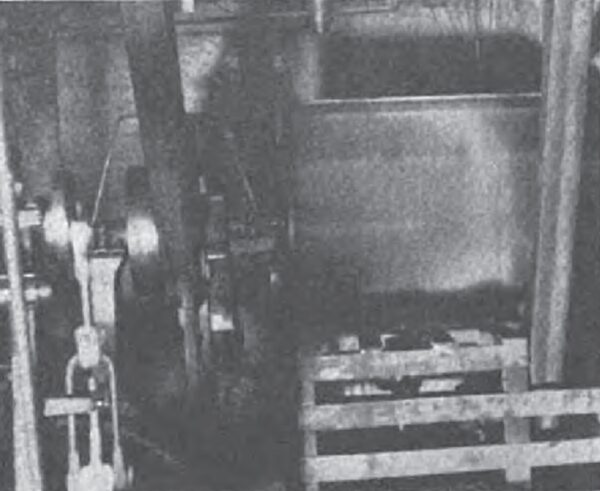
| Fig. 2 Slip Pump and Blungers |
Three blungers operate on the wet-process slip, the remaining one on the dry-process. The charge is blunged 1 hour to give the necessary creamy slip. Three agitated storage cisterns below the floor receive the slip from the blungers. The three blungers deliver into two of these, while the third receives the dry process slip from one blunger.
Fig. 2 is a view on the delivery side of the blungers with the wet-process double-acting slip pump in the foreground. This pump delivers wet-process slip from the two cisterns to the lawn room in the main buildings located up hill from the railroad. A similar pump likewise handles the dry-process slip from the third cistern to a second lawn room. These pumps are also equipped with 20-hp. Westinghouse motors.
SAGGER ROOM
The saggers for holding insulators while burning in the kilns are made as usual in a separate department raw materials used for making these saggers are Kentucky ball clay, Pennsylvania sandy clay, wad clay and grog. The equipment here consists of a small dry pan, grinder, vertical pug mill, small wad mill and a 28-ton steam press having a pressure of 250 lb. per sq.in. for forming the sagger. The wad mill is a small affair extruding a plastic clay string about a} in. diameter. This is used between the top edge and the lid of the complete sagger for sealing in the ware, thus preventing the entrance of kiln gases and resultant contamination of the ware.
The formed sagger from the steam press is dried thoroughly by placing over a gas flue. It is not necessary to burn the saggers in separate kilns, as often practiced. The green product from the drying flue may be filled and burned at the same time as the ware it contains.
LAWN ROOMS
The slip for dry body or low-voltage porcelain is delivered from the blunger house as mentioned above to a cistern in the low-voltage lawn room. Thence it is pumped onto a 120-mesh lawn shaker screen and returns to a second cistern, where it is agitated until delivered by a second pump at 80 lbs. pressure to the filter room.
| |||
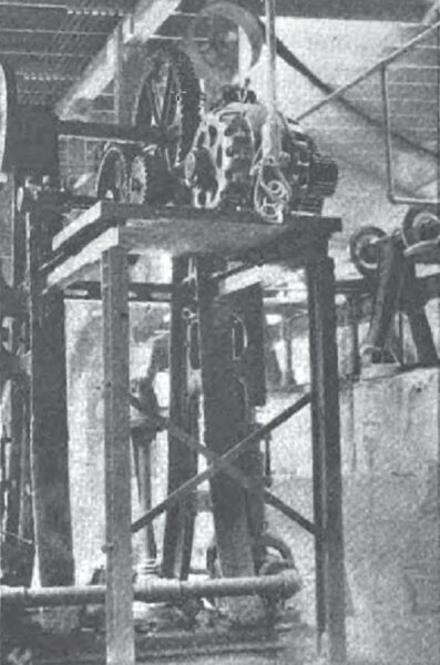
| Fig. 3 Lawn Room Pump |
| |||
| Fig. 4 Lawn Room Switchboard |
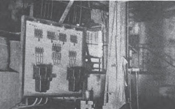
The larger or high-voltage lawn room is equipped with two units, each consisting of a cistern receiving slip from the blunger house, a 120-mesh shaker lawn, a second cistern and a pump delivering the finished slip to the filters. Fig. 3 shows one of the double-acting pumps in the high-voltage lawn room driven by two-phase electric motor, and Fig. 4 shows the switchboard, carrying oil switches, fuses and knife switches controlling the pump motor circuits and shaker lawn motor. The shaker lawn appears in Fig. 5.
| |||
| Fig. 5 Shaker Lawn |
| |||
| Fig. 6 Pebble Mill for Raw Glazes |
The glazes made from white ingredients or Albany slip without frits are ground in three 1,000-lb. pebble mills adjoining the high-voltage lawn room. Fig. 6 shows a portion of one of these arranged with belt drive.
FILTER ROOM
Production of the plastic cake from the slips as they are pumped in from the lawn rooms is carried on in one location with a battery of seven 80-lb. leaf type, Patterson filter presses. One press is used on low-voltage and six on high-voltage body. For dry-process low-voltage porcelains, the cakes from the filter press are elevated to a drying room located over the kilns and after thorough drying are pulverized and tempered for pressing to shape.
For wet-process, high-voltage porcelain the plastic cakes are piled in a heap, beaten with mallets into a solid mass and permitted to age for a period varying from 1 to 3 days. During this time the moisture becomes evenly distributed throughout the mass. Just before it is sent on to the shaping department it passes a vertical type pug mill. This operation consolidates the clay, works out any air bubbles and forms it to suitable slabs for working.
PUGGING
The pug mill consists of a vertical hollow cylinder, in the middle of which revolves a shaft carrying projecting blades. The blades, being set at an angle, gradually force the clay downward, at the same time kneading and mixing it. At the bottom of the cylinder it is forced through an opening in the side, coming out as a continuous bar from 4 to 6 in. in diameter. From this bar slabs are cut of suitable length for subsequent processes. Pugging is an important operation in the manufacture of insulators, for upon it depends the freedom of an insulator from checks and air bubbles and the consequent ratio of dielectric strength.
SHAPING HIGH-VOLTAGE INSULATORS
The jigger room is equipped with about ten jiggers and several hot presses. The jigger as here employed consists of a vertical shaft revolving at a moderate speed and having at the top on a level with the workmans bench a plaster of paris mold to form the outside shape of the piece. A lump of pugged clay is dropped into the mold and formed roughly to shape by hand. The metal template, called a tool or shoe having the contour of the inside surface of the insulator, is then pressed down by means of an arm attached to the machine and the finished interior outline given. The mold containing the shaped piece is then removed and another mold dropped into place for the next piece.
The pieces are permitted to remain on shelves in molds for 24 hours. The mold is then opened up, the piece removed and set upon boards or cars in readiness to be taken to the drier.
HOT PRESSING
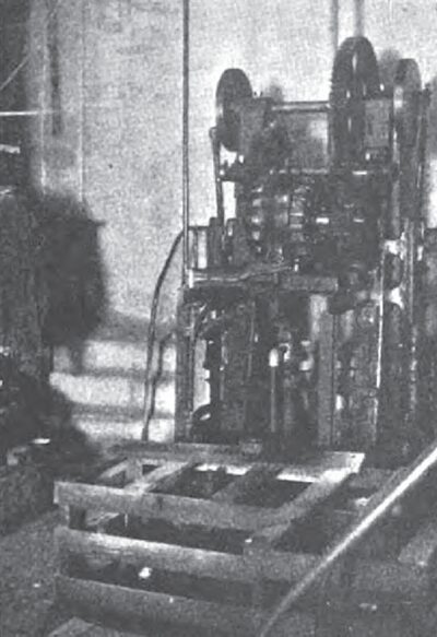
The hot press room contains eight hot presses, a machine similar in general characteristics to the jigger. Fig. 7 shows one of these ready for the operation. Different from the jigger, the table below does not revolve, but holds the plaster of paris mold solidly in position. A circular billet of clay with one end rounded is thrown with round end down into the mold.
| |||
| Fig. 7 Hot Press |
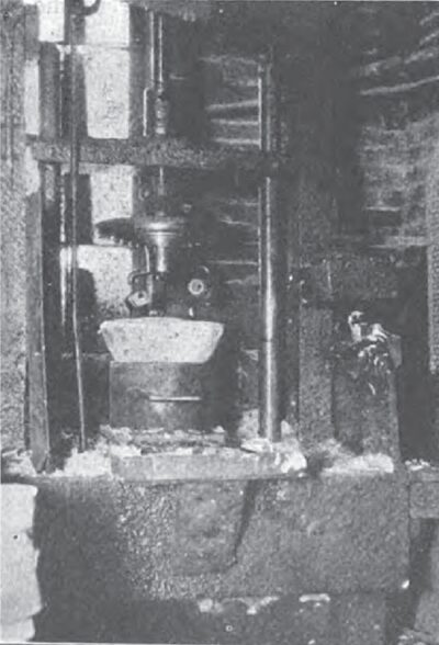
While the machine is in the position shown two gas flames play upon the upper cast-iron half of the mold, keeping it warm between movements. These gas burners are visible between the upper and lower halves of the mold. It will be noted that the upper half is threaded and grooved to form the inside of the insulator. The crosspiece above acts as a guide for the threaded mold shaft.
After the clay is placed in the lower half, the operator throws on power, causing the shaft to revolve, and due to threads on shaft of the same pitch as the threads on the mold the upper half moves downward quickly and enters the clay, forcing it to till all the space between the upper and lower halves and simultaneously forming a thread on the interior of the piece. At the end of the travel the piece is thus shaped, the power is reversed and the upper half unscrews upward to its original position, to be heated again by the gas fumes.
The heating of this mold causes a film of steam to form when it comes in contact with the wet clay, giving a clean-cut surface and, still more important, permitting an immediate removal of the iron from the clay without danger of sticking. The iron mold is hollow, avoiding suction by permitting air to pass through small holes when it is withdrawn. The operation may be repeated very rapidly, the speed being entirely dependent on how quickly the lower half may be removed from the machine and a new plaster of paris mold inserted.
As in the case of jigger work, the piece is permitted to remain in the mold 24 hours before removing and transporting to the drier.
OTHER SHAPES
The method of shaping the high-voltage pieces depends upon the article to be made. Pieces of a diameter rather large in proportion to the height, such as pin and suspension insulators, are made on the jigger or press as above described. Long corrugated pieces like bushings and post insulators are turned. This turning may be done on a special lathe or jigger. It is essentially the same as wood turning. Wet turning is most advantageous where possible because of increased speed and lack of dust.
Plain tubes are made by extrusion from a machine composed essentially of a cylinder and a piston. In the bottom of the cylinder is placed a die having a hole equal to the outside diameter of the desired tube and a concentric mandrel to form the bore. In the case of small tubes several may be extruded simultaneously. The cylinder is filled with pugged clay, the piston moves slowly down, squeezing the clay from the die in the form of a continuous tube. Suitable lengths are cut off and straightened by rolling. The head is pressed up on small tubes and spun on in the larger sizes.
DRYING HIGH-VOLTAGE BODY
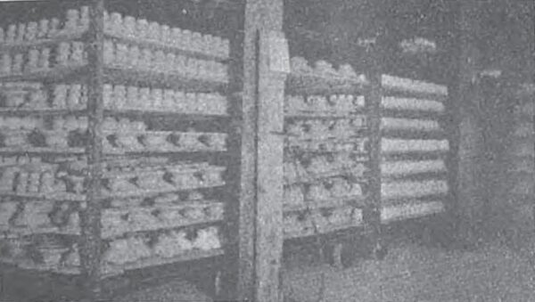
All of the various pieces having been placed on rack cars after removing from the molds, these are wheeled to the entrance of the large drier as shown in Fi. 8. This drier is 104 ft. long and three tracks wide. It has a capacity of nineteen cars per track. One track handles cars containing larger ware and operates at a rate of one car entering every 3 hours, or giving a drying time on each car of 57 hours. The two other tracks carry cars of smaller ware and operate on a 2-hour schedule, consequently giving a drying time of 38 hours per car.
| |||
| Fig. 8 Rack Cars Entering Drier |
| |||
| Fig. 9 View Along Drier Showing Blower Drive |
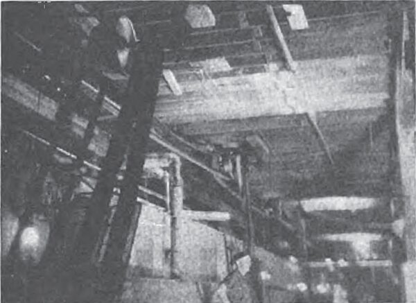
Proper regulation of drying rate is one of the most important features of insulator manufacture. Extreme care must be taken or cracks and warping will develop, affecting both the mechanical strength and dielectric properties of an insulator. Before the advent of the mechanically operated, automatically controlled drier in the ceramic industries it was necessary to place the ware in a heated room with little humidity control for a period of from 2 to 6 weeks.
The insulation at this plant is a Hurricane drier manufactured and installed by the Philadelphia Drying Machinery Co. The humidity and air supply is automatically controlled by wet and dry bulb Tycos regulators. Fig. 9 is a part view along the drier showing blower drive and control.
There are nine fans alongside the drier, all driven by a 25-hp. two-phase motor. Steam at 100 lb. pressure is supplied to the coils. All steam used in the plant is purchased from an adjoining factory. An air pump furnishes 25 lb. air pressure to operate the diaphragm valve on the controls. There are four sets of control mechanism for automatically handling the supply of steam and air to the drier. Pieces from the drier are conveyed to the glaze dipping room.
DRY-PROCESS, LOW-VOLTAGE ROOM
Low-voltage body in the form of filter cake, having been passed through the drier on cars along with the high-voltage shapes and subsequently stored in a heated room over the kilns, is sent to the low-voltage shaping room. Here it is rough ground to nut size and mixed with just sufficient water to make a damp powder without becoming plastic. It finally passes through a plate type grinder running at 2,200 r.p.m., coming out as a fine damp powder. Two complete grinding units perform this operation.
Arriving in the press room through a chute from above. the powder is shaped in about fifty different hand Dresses to the forms required. The dies used in these Dresses are lubricated with a special oil known as Franklin XX. After trimming off the rough edges by hand, an operation known as fettling, the pieces are transported on trays to the dipping room.
DIPPING ROOM
Both high- and low-voltage bodies are dipped by hand in tubs of wet raw glaze. The ingredients of the glaze are ground with water as previously noted. Colors are often introduced in glazes to identify electrical circuits when the insulators are in place. These include chromium, cobalt, Albany slip, a dark brown and the natural white. Before dipping in the glaze the pieces are immersed in water to remove dust which may have accumulated through the process. The dipped pieces are allowed to drain and dry in the air and are then ready for the kiln. In cases where it is desirable to roughen part of the surface of the insulator to give friction where in contact with insulator pin or for other reasons, the part is coated with paraffine, then with a mixture of sodium silicate and gum Arabic and dipped in high-voltage sand. The sand adheres to the sticky surface, giving the desired roughness. The portions of all insulators which come in contact with the sagger are paraffined.
FIRING
The kiln room is equipped with twelve updraft periodic kilns of 12, 14 and 16 ft. diameters. Materials and saggers are handled in and out of the kilns by Lowden overhead conveyors. When the saggers of ware are stacked in the kilns, the green or unburned saggers are placed near the top above the jack saggers.
| |||
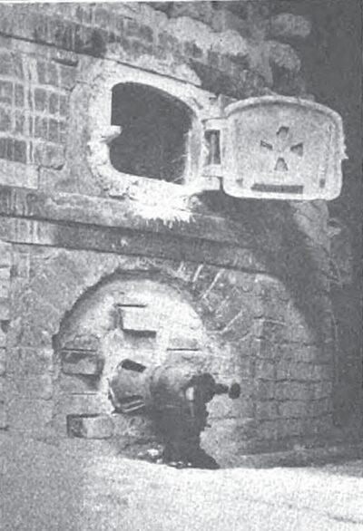
| Fig. 10 New Type Gas-Fuel Oil Burner |
| |||
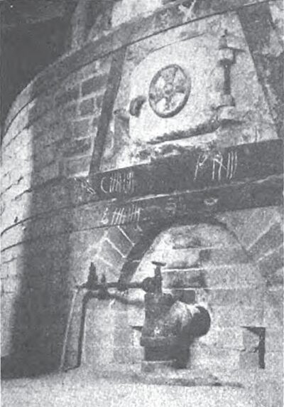
| Fig. 11 Natural Draft Gas Burner |
Actual firing time varies from 40 hours on the small ware to 70 hours on the larger pieces. During the first stage the temperature is raised and the moisture is driven off. This moisture includes that merely mixed 'with the clay which has not been driven off in drying and also that which is chemically combined with the clay particles as an essential constituent. The latter action is accomplished at about 1,200 deg. F. and is a true decomposition of the clay substance. In the next stage the temperature is raised to proper value for the vitrification to porcelain and is held there until a heat saturation point is reached as indicated by cone 11. This is a delicate stage. If the temperature is too low, the porcelain is underfired and porous, and if too high, it becomes brittle, full of bubbles and therefore electrically weak. During the last stage the kiln is allowed to cool gradually so that the ware is well annealed. The entire cycle requires about 5 days.
FUEL
Three of the kilns burn coal, three gas with natural draft burner and the remaining six burn fuel oil or gas. The combination burners on two of the kilns are the Maxon Premix and on four kilns are Spencer burners made by the Leader Furnace Equipment Co., Cleveland, Ohio. Fig. 10 shows the new type gas-oil burner applied through the ash door of a kiln. The oil is sprayed into the space below the firebox at a pressure of 30 to 40 lb. with air pressure at a maximum of 3 oz. The oil nozzle is cut with cross-shaped slot. Fuel oil is purchased from the Oklahoma fields and is a refining residue. The main storage tank holds 200,000 get, with an auxiliary tank of 6,600-gal. capacity.
Fig. 11 is a View of the natural draft burner adapted through ashdoor.
An average kiln consumes about 2,000 gal. of fuel oil per burn, making a fuel cost of $70. To do the same work 220,000 cu.ft. of gas is required at a cost of $100. Twelve tons of coal at $5 per ton is used per burn, at a cost of $60 plus the cost of cleaning and ash-handling. It is obvious that oil is the most economical fuel for this plant.
ASSEMBLING
After the burning operation the insulators are sent to the assembling and testing departments. The parts of pin and suspension insulators are fastened together with Portland cement mixed neat and just thin enough to flow readily. The tubes of roof and wall bushings, not being exposed to much mechanical strain, are fastened together with an asphalt compound which incidentally gives increased insulation.
ELECTRICAL TESTING
Dry-process porcelain, being for low voltage, is not ordinarily subjected to electrical tests. One the contrary, the wet-process, high-voltage product must undergo not only electrical but also mechanical tests. Electrical tests which do not injure the test-piece, to determine size and proportion such as measurements of dry and wet flashover, corona voltage, etc., are usually made on a few samples. Electrical tests are made where the proportions and size are assumed to be correct and it is required to determine the limitations of the porcelain or compare with some standard.
Where the ultimate limit is to be determined, the piece is destroyed, which prevents the application of the test to more than a small fraction of the product. The puncture under oil test and the ultimate mechanical strength test are examples. The particular sample being destroyed, the only value of such tests lies in what may be inferred as to the qualities of the large proportion not tested.
Where the material is merely required to come up to a certain standard, only pieces failing to meet it are destroyed. Common examples are the routine flashover test in the pan applied to all insulators, and with suspension insulators the test load. Good judgment is required in laying out such tests. They should be severe enough to remove really defective material but not injure or weaken average or good material. This is complicated, since there is no sharp distinction between good and bad, and all intermediate grades will exist. For commercial purposes the test much be such that most of the material if of average quality will pass it, and the pieces so selected will stand the working conditions. If these features are not consistent, a design of stronger proportions must be selected.
DIMENSIONS OF PORCELAIN PIECES
The accuracy to dimensions of porcelain is affected by a number of factors. There is first the wear of the molds. This is important with both steel and plaster molds. The greater the variations which can be permitted the longer the life of the mold. Next comes the shrinkage in drying. This depends upon the amount of moisture in the clay, and is difficult to control very closely. Finally there is the shrinkage in firing. Of course exactness in dimensions can be obtained by gaging and rejecting all parts outside the limits, but this is scarcely possible except in the few instances in which the rejected pieces can be used for other purposes where exact dimensions are not so important. In some cases the variation can be reduced by special attention to the moisture content, by trimming after drying, or grinding to size after firing. All such methods cause added expense, and unless really necessary are avoided. Good commercial limits which do not involve any unusual precautions are a total variation from minimum to maximum of 1/32 in. per inch for dry process porcelain, and 1/16 in. per inch for wet process.
SHIPPING ROOM
The inspected and tested insulators finally arrive at the shipping room, where they are packed with shavings in barrels and crates. The finished package is weighed over an American Kron scale and passed into the cars.
CERAMIC LABORATORY
In addition to research work the ceramic laboratory controls the various operations in the plant. Moisture factors must be taken on all raw materials. Porosity and screen tests are made on clays. Chemical analysis is made on feldspar and elutriation tests on flint and feldspar. Some test must be made of the lime content of the flint.
Ball clay vitrifies at cone 11 but does not overfire, because of long vitrification range. It also has high mechanical strength. Electrical porcelain is a vitrified ware, where tableware made in this district is only semi-vitreous. Naturally the body used is difficult to dry because of high ball clay content. China clay runs more uniform and causes less trouble.
The body mix is controlled by regular tests which effect the length of time to age, the moisture in the filter cake and the operation of the drier. The uniformity of mixture secured by aging is most important in the manufacture of porcelain. It resembles chemical stoneware in this respect.
