[Trade Journal]
Publication: Electric Traction Weekly
Cleveland, OH, United States
vol. 4, no. 22, p. 528-530; 539, col. 1-2
Insulation of High Tension Transmission Lines.
BY FRANCIS S. DENNEEN.
Mr. Francis S. Denneen of the Ohio Brass Company presented an exhaustive and able paper on high tension insulators, outlining their development, details of manufacture, methods of testing, and concluding with a suggested set of specifications for ordering insulators. The following is an abstract of the paper:
Up to 1897 glass was used almost exclusively for high tension insulators even on transmission lines carrying up to 16,000 volts. The first porcelain insulators were made by the dry process which depended largely upon the glaze for the insulating qualities. Later the wet process was developed. By this method of manufacture and with the proper mix of the materials, making up the porcelain body, it was possible to produce porcelain of great mechanical and electrical strength, the body being dense and homogenous and highly vitrified.
At the present time glass and porcelain are the only materials used commercially for the insulation of high-tension lines, and the former is fast becoming limited to use on lines where the pressure does not exceed 10,000 to 15,000 volts.
The glaze of a porcelain insulator is a very important feature, not because it is depended upon for actual insulation, but because it serves to give the porcelain body a surface which will be non-hygroscopic and absolutely smooth, so as not to retain dust or moisture readily. Difficulty was experienced with the early porcelain insulators because of the glaze checking or crazing after being in service a short time, and much trouble was also experienced from pitting, due to the elements attacking the glaze. These troubles have all been overcome, and a good piece of modern porcelain is so glazed that it will stand up for an indefinite period, under the severest weather conditions, without showing the slightest tendency to craze or pit.
 |
| Fig. 1. Insulation of High-Tension Transmission Lines. |
White glaze was first used for porcelain insulators, but it was found that these were too attractive as targets for the hunter and the small boy, and a dark brown has now become standard with most users. A limited number of consumers demand an insulator with a slate-colored glaze, asserting that this color is less conspicuous, particularly where the insulators are mounted on galvanized-steel towers. Other colors, red, yellow, blue and green, are sometimes called for by power companies who wish to distinguish the various circuits.
Discussing now the effect of an electrical charge on a few elementary forms of insulators, reference is made to the drawings herewith.
 |
| Fig. 2. Insulation of High-Tension Transmission Lines. |
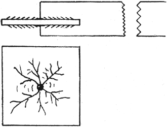
In Fig. 1 is shown a thin plate or disk of insulating material, such as glass, having on each face a small terminal connected to a source of E.M.F.
Starting with a low potential, only current to charge this small condenser will flow, but as the potential is raised the air in the vicinity of the electrodes breaks down, producing a brush discharge, which has the effect of increasing the size of the electrodes. As the tension is further increased, the zone of ionized or broken-down air spreads over the surface of the plate, and finally streamers form across the surface, aiding in breaking down the air further from the electrodes. If the voltage is sufficiently increased, this process continues until the streamers unite around the edges, forming a short-circuit, or puncture of the plate occurs.
It must be borne in mind that this is not the result of surface leakage, but of breaking down of the film of air next to the insulator.
Once the air has become ruptured, the spreading of the streamers will be affected to a certain, degree by the shape and dimensions of the solid dielectric.
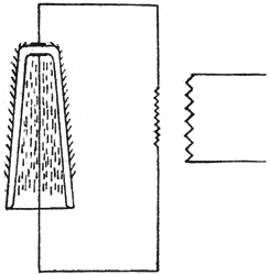
In Fig. 2, for instance, if the potential is carried sufficiently high, the air within the chamber breaks down, and the effect is the same as if the chamber were filled with a conducting fluid.
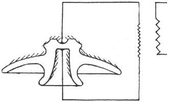
In Fig. 3, for instance, appears an insulator head, and under such a test the streamers would start at first the same as in Fig. 1, but upon reaching the downward projection they are forced away from the streamers on the top surface until a point is reached where the electrostatic field is no longer strong enough to break down the air, and the streamers die out and further rupture of the air adjacent to the insulator ceases.
With these points in mind it is a comparatively simple matter to follow out in detail the action of a regular insulator under varying load conditions.
Surface insulation has little to do with insulator performance, and the actual leakage over the insulator will be inappreciable unless the surface is covered with dust or water or some other foreign substance. Under high potentials, the wet surface should be considered as a conductor, while the dry surface should be regarded only in relation to the electrostatic effects described.
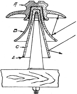
Considering now the action of an ordinary insulator under varying service conditions. Assume that the one appearing in Fig. 4 is operating at its normal line voltage and that all surfaces are dry and clean. If properly designed for this voltage, the electrostatic field about the different shells will be too weak to break down the air, hence no brush discharge or "static" will be in evidence. Let the potential be increased, and as the electrostatic field becomes more intense the air fails and brush discharge is seen around the different shells near the conductors, and at the cemented portions. As the potential is raised, streamers form, further increasing the zone of ruptured air until the air near the shells, becomes sufficiently conducting that an arc forms from shell to shell, and finally from the pin to the wire, the arc straightening out to nearly the shortest distance between them, but around the edges of the shells. This, of course, assumes that the insulator is sufficiently strong to withstand the flashing-over voltage without puncturing.
 |
| Fig. 3. Insulation of High-Tension Transmission Lines. |
Under heavy rain storm conditions, the entire top surface at once becomes wet and the potential, of line is immediately carried to the outer rim of this piece. Some of the rain beats against the lower shells, wetting them, not only where it strikes, but on the under surface of the upper shells, due to spattering, the amount of surface so acted upon depending upon the force and angularity with which the rain is driven and upon the design of the shells. Under a severe storm it is quite possible for practically all of the insulator surfaces to become wet and conducting except possibly the under surface of the center or bottom shell. If the insulator is properly mounted with respect to the cross-arm, and the center shell is correctly formed, this inner surface will remain dry. In the meantime the line potential has followed the wet surfaces of the insulator until it has reached the bottom edge (E) of the center shell so that the full line potential is now being carried by the center shell alone.
The insulator can now fail in either of two ways: (a) by rupture of the air film adjacent to the inner surface, because of the intense electrostatic field, resulting in an arc from the shell to the pin, or (b) by puncture of the shell itself.
In case of the formation of an arc, the actual current flowing would be of low value, because of the high resistance of the thin film of pure water forming the conducting surface over the insulator, and this would at once result in a drying action, due to the heat from the current. As this drying process continues, the resistance becomes too high to permit maintaining the arc, and the discharge between line and pin ceases.
It is interesting to note that the drying action is maximum at the neck of the smallest shell, for here the current density is highest, and therefore the heating effect is greatest.
 |
| Fig. 4. Insulation of High-Tension Transmission Lines. |
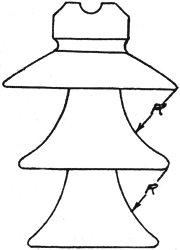
The contour of the different pieces has much to do with the wetting of the shells in a storm. The shape of a shell may be such as to deflect the air currents, thereby carrying the rain up into recesses which would otherwise be dry. The flare of the skirt portion of the shells also plays an important part. Referring to Fig; 4, the second shell (B) is flared or curved outward at the bottom, and in a driving rain the drops will be deflected against the under side of the top portion, as shown by the arrows, because of the curved surface. The third shell (C), however, is straight, and, as the arrows indicate, the raindrops are deflected downward, so that the shell above is not spattered.
There are other features which enter into the question of design however, which make the curved shell particularly advantageous, and it is therefore necessary to regard these different points of merit of the two types carefully in making a choice for any particular design proposition. With a given diameter and height, maximum sparking distances between the rim and shell of the adjacent parts can be obtained by using the curved type of shell, but there is a point where this advantage is lost because of spattering the other shells, as already described.
Another advantage possessed by the curved shell is that for a given potential difference between the surface of the shell and the rim of the shell above, the tendency for discharge between these two points will be considerably lower than with the straight type of shell. It is well known that discharge between a point and a plane surface will take place at a lower potential difference than would be required to cause a discharge from such a point to the concave side of a spherical surface all points on which are equally distant from the point forming the other electrode. In the case of an insulator (see Fig. 5) the rim of any shell corresponds to the point, and the curved shell below to the spherical surface. In many designs the flare of the skirt is determined by a radius swung about the rim of the shell above as a center (see Fig. 5), the curve beginning at the theoretical dry line, based upon the assumption that the rain falls at a 30-degree angle with the horizontal.
 |
| Fig. 5. Insulation of High-Tension Transmission Lines. |
From the foregoing it would appear that the ideal multi-part insulator of the umbrella type should have its center shell so designed that alone it could carry the full line potential for an indefinite period without puncture or arcing over. This condition actually obtains on many insulators for the lower voltages, but it is not always true of those for voltages of 60,000 or more.
In asking a manufacturer to recommend insulators for a line, therefore, he should be given complete details covering the various points mentioned, in order that he may intelligently consider the problem. It is often possible to get a good idea of the troubles to be met in the territory under consideration from other lines already operating in that territory, or in the immediate vicinity. Of course, such a line would probably not be working under the same voltage conditions, but a knowledge of the troubles met under the operating voltage, and with the insulators employed would be of great service.
Of considerable importance in connection with the selection of insulators is the question of disturbances from lightning.
Lightning troubles are not so marked on lines operating at voltages below 30,000, undoubtedly, because the insulation of these lines does not need to be 11early so perfect as for operating voltages of 50,000 or 60,000. With the moderate insulation required for 30,000 volts or less, the loss of a static charge from the line would be rapid and this charge would not be built up to excessive values before arcing around the insulator would produce relief in the line. At the same time the line potential: would not be high enough to cause the line current to follow-when discharge from line to pin occurs. Numerous methods have been devised and tried out for protecting the high tension lines against atmospheric electrical disturbances, among which are included various types of lightning arresters and different schemes for shielding the lines by means of lightning rods on the poles, and wires strung parallel to the lines and grounded at frequent intervals. This subject has been given considerable thought and study during the past two or three years, and from various reports submitted by those who have carefully watched the operation of the different devices, it would seem that the use of grounded wires placed above the transmission lines greatly minimizes insulator troubles from lightning.
The question of insulator pins has long been an unsettled one, many engineers still maintaining that nothing but the wood pin should be used, while others insist upon a metal pin. For low voltage lines, where the insulators are small and the spans comparatively short, bringing light mechanical loads upon the pins, a good quality locust or oak pin thoroughly treated with oil or paraffine meets all requirements cheaply and effectively. It must, of course, be remembered that to get satisfactory service from a wood insulator pin, the design of the insulator itself must be such as to insure against burning the pin from brush discharge or leakage. For insulators of the larger type, where the pin must extend a considerable distance above the cross arm, thereby placing a more severe load upon the pin, and where this load is further increased because of the use of longer spans, a metal pin should by all means be employed.
Many advocates of the wood pin hold that the electro-static stress placed upon the insulator when used with an iron pin is much greater than it would be if a wood pin were used. This means that the insulator would be more liable to break down or flash over under excessive voltage variations than if mounted upon wood pin. It is quite true that the wood pin possesses, for a time, certain insulating qualities, but this is not of any considerable value with the higher voltages, say 33,000 and more, particularly after the pin has become old, and, to a certain extent coated over with dust.
It is at once evident that dependence cannot be placed upon the insulation afforded by a wood pin, and therefore in selecting an insulator one should be chosen which under the most severe conditions will absolutely maintain the insulation of the line, when the pin is a good conductor and thoroughly grounded.
A thoroughly insulating pin would indeed be ideal for with it the thickness of the dielectric would be considerably increased, thereby greatly decreasing the strength of the electro-static field about the insulator, hence increasing the factor of safety. This would mean that the air adjacent to the insulator would not become ionized, and there would be no brush discharge.
However, such a. pin cannot at the present time be made, because of the mechanical difficulties involved. Unfortunately we have no suitable insulating material of sufficient mechanical strength to meet this class of service.
The transmission line has in many cases been hampered by the desire of the engineer to introduce some more or less new and original ideas, putting, as it were, his personal stamp upon the line. It is, of course, true that in the early days of porcelain insulator manufacture, the maker did only what the engineer desired, but as soon as the demand for insulators warranted, the manufacturer at once placed himself in a position to design insulating devices, and equipped himself with everything necessary for the study of insulation problems.
The result is, that today the modern high tension insulator factory because of its experience and facilities for investigation, is far better equipped to design insulators for a given service than the average engineer who has had but little experience in this class of work.
In drawing the specifications for insulators, points often come up which make a proposition unnecessarily difficult and expensive for both the purchaser and the manufacturer, and this condition could often be prevented if the manufacturer were given a full understanding of the actual requirements, and not hampered by more or less foolish specifications which the engineer, when he drew them up, knew could not be met.
The following suggestions to aid in drawing insulator specifications are being offered with an idea of making them cover all general insulator requirements. These specifications are made so that they can be commercially met by the manufacturer, while at the same time insulators made in strict accordance with them should fulfill the requirements perfectly under all ordinary conditions.
SUGGESTED SPECIFICATIONS FOR INSULATORS.
Insulators should be made of a grade of dense porcelain, best suited for high-tension insulators, and the burning should be so done as to insure thorough vitrification of the pieces without over-firing.
The porcelain body should be practically non-absorbent, and pieces broken from any insulator should not show an absorption in excess of one-tenth of one per cent. The absorption test should be made by thoroughly drying the pieces in an oven before the first weighing; they should then be immersed in water, for 48 hours, after which all surfaces should be carefully dried and a second weighing made. The increase in weight expressed as a percentage of the original weight will show the absorption.
All insulators should be given, a dark-brown glaze (or other color required) on all exposed surfaces, those surfaces which are cemented together and those upon which the insulator rests in burning not to be glazed. The pinhole should be left unglazed if the insulator is to be cemented to an iron pin.
All cemented joints should be carefully made with neat, Portland cement of the best quality, and the assembly should be so done as to leave no hollow spaces or voids between the cemented surfaces. In assembling the cement should be mixed only as needed and in the proportions of 80 per cent. cement and 20 per cent. water, and no cement which has been mixed for more than 30 minutes should be used. The assembling should be so done as to bring all of the various parts in correct alignment.
All parts should be carefully inspected as they come from the kilns, and any which are chipped or cracked, particularly at the surface where the cells are cemented together, should be discarded. Badly warped or distorted pieces and those having checks of appreciable depth at any points on the surface should be rejected.
All parts should be tested for one minute at full-line potential, except in cases where the design of the piece will not permit reaching this voltage without flashing over. In such cases the test voltage should be within 5,000 volts of the flash-over value.
Each assembled insulator should be tested to at least double the full-line voltage for a period of not less than three minutes.
The insulator should be capable of withstanding a rain test at twice the operating voltage for a period of 10 minutes, without flashing over or injury to the insulator, the precipitation being at the rate of 1 1/4 ins. in five minutes and directed against the insulator in a fine spray at 45 degrees.
All insulators to be operated at 23,000 volts or more should be tested with at least one kilowatt of available generator capacity for each insulator under test.
In the part tests each piece should be immersed in water to completely cover the cementing surface, and the inside should be filled with water to practically the same depth, and the potential should be applied to the two wet surfaces. In testing assembled insulators they should be inverted with the heads immersed to the tie-wire groove, the pinhole being filled with water to the full depth of the thread.
In conclusion, it is urged that the policy be a liberal one when it comes to the expenditures of the transmission line. As a general thing, no expense or trouble is spared in making the power plant equipment complete, and in fully safeguarding this equipment. On the other hand, the transmission line, which in the event of failure for any cause makes the power house entirely useless until the line trouble is corrected, is often provided for last, the expense being cut down to the lowest possible figure. Such a system is bound to have line troubles causing heavy expense for repairs and losses due to interrupted service. These losses could be almost entirely prevented by the use of better insulators and proper line protection at the outset, and the cost of this insurance would be less in amount than the total for losses due to interruptions during a few months of operation.
Discussion on Insulators
Mr. Kelsey asked if the speaker advocated the use of steel poles, cross arms and pins. He said he had had insulators puncture under tie wires and short circuit to the pins. He asked what would be the effect on an all metal structure.
The speaker said that the metal pole would afford an immediate ground and the insulator would break or burn off so that the ground could be readily seen. He said that with modern porcelain insulators troubles from punctures were very rare. Usually lightning goes around the side of the insulator and shatters it. The dielectric has a capacity to stand shock up to a certain point. In the case of lightning the time element came in. The stroke flashes over the insulator before it has time to puncture the curved surface.
Mr. Kelsey said that he agreed with the speaker that metal pins' and arms were desirable for power transmission companies transmitting large quantities of current, because, due to the larger currents carried, the insulators would be more liable to burst, but he was rather doubtful of their use for railway circuits.
Mr. Sloat, of the Ohio Electric Railway, asked if the fact that the top of the insulator was not glazed had any effect on its life.
The speaker said there was no objection to the unglazed surface as the material was non-absorbent to the extent of 1-100 of 1 per cent. Ink was used in tests to show non-absorption. The speaker explained that the upper surface was unglazed because in the burning process the insulator rested on this surface.
