[Trade Journal]
Publication: Street Railway Journal
New York, NY, United States
vol. 20, no. 16, p. 550-559, col. 1-2
THE BOSTON & WORCESTER STREET RAILWAY
MASSACHUSETTS has been the home of the electric railway from the early days of its inception. Pioneer work of the most advanced and daring character, which has since contributed largely to the standards of practice in other States, was done in the "Old Bay State" in the strenuous years of costly experiment which laid the foundations of the mighty street railway industry of to-day. Few, if any, States can boast more splendidly equipped and finely operated local systems than the world-famous "West End," of Boston, now the "Boston Elevated," or the "Worcester Consolidated," with its far radiating branches into the country round about the "Heart of the Commonwealth." Added to these the lines of the Massachusetts Electric Companies, the Boston and Suburban Street Railway Company and those of Springfield, on the west center, gridiron the eastern and central portions of Massachusetts with a network of tracks, which goes far toward completing the total of 2309 miles of track owned at the beginning of 1902, constituting a remarkably well-served territory as regards local traffic. Up to the present time the development of the Massachusetts electric railways has been chiefly from city to town, and from town to town. The strictly high-speed interurban railway has obtained its growth chiefly in the middle or eastern portions of the West, notably in Ohio, Indiana, Illinois and Michigan. Gradually the North Atlantic States are coming to realize the need of more rapid transit between urban centers of population, and particularly is this true in Massachusetts, where the entire eastern half of the State pours an enormous daily traffic into Boston, which is constantly becoming more visibly influential in the remotest corners of the State, and still further securing its strategic position as the financial, commercial and transportation headquarters of New England.
| |||
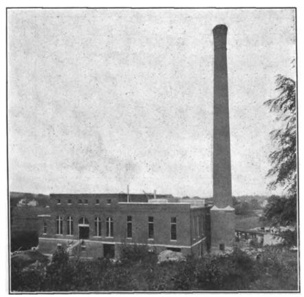
| Power Station at South Framingham |
About 40 miles west of Boston, by air line, lies the city of Worcester, with a population in 1900 of nearly 120,000, noted as a manufacturing, educational and railroad center, and, strictly speaking, just without the true suburban limit. For about five years it has been possible to travel from Worcester to Boston by trolley cars, over a somewhat circuitous route about 50 miles long, the time required being in the vicinity of five hours. Some six changes of cars were required, but the fare of 55 cents against $1, as charged by the Boston & Albany Railroad, the steam line serving the two cities, frequently offset in the minds of pleasure-seekers the run of a single hour on the steam road, and created a perceptible traffic in the excursion line over the route, which offered a pleasant ride through some of the most beautiful suburbs of Boston, via either Chestnut Hill reservoir or Newton, through Auburndale, Wellesley, Natick, South Framingham, Framingham Center, Marlboro and Shrewsbury to Worcester.
The need of a direct line between the two cities had long been felt, however, so that in 1901 the Boston & Worcester Street Railway Company was incorporated, its object being to build and operate a high-speed through electric line between terminii, covering the distance of 40 miles in about. two hours, on a fare of 35 cents. At the same time it was proposed to provide rapid transit from the suburban towns along the line into the heart of Boston, over a reserved or private right of way in the outer districts. Construction was begun in November, 1901, and it is expected that the first portion of the line, or that between Boston and Framingham, will be in operation Nov. 1 , 1902, while the line from Framingham to Worcester will be opened for traffic probably in the early part of the spring of 1903.
| |||
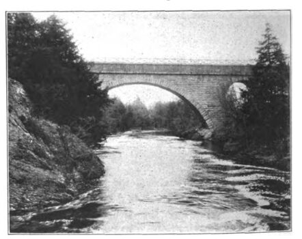
| Bridge at Newton |
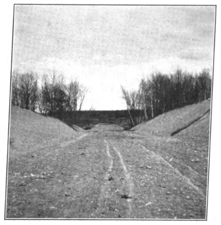
The Boston & Worcester Company will take a passenger at Park Street Subway Station, Boston, coming from any point on the immense surface and elevated system of the Boston Elevated Railway Company, and for 35 cents carry him 40 miles west over an air line route to Worcester, there transferring him free of extra charge to any car line of the Worcester Consolidated Street Railway Company's large system. A ride of from 50 to 60 miles for 35 cents is thus possible in the plans of the new company with its connections, a large part of which is at high speed on private right of way. The cars of the Boston & Worcester on leaving the subway at Park Street will run up the Public Garden incline, going thence to Columbus Avenue, up Massachusetts Avenue to Huntington Avenue, and thence to Brookline Village, over the tracks of the Boston Elevated Railway Company, out Boylston Street, Brookline, to the end of the present line of Chestnut Hill cars, near Holyhood Cemetery. At this point the Boston & Worcester Company's own tracks begin, and run through to Framingham, over a superb boulevard road, the tracks being laid on ties in about 1 ft. of ballast in the middle of a reserved grass plot right of way at least 50 ft. wide. The line upon leaving Brookline passes through Newton, then along the old Worcester turnpike to Wellesley Hills. At Newton Highlands connections are made for Norumbega Park and Waltham, and at Wellesley Hills for Wellesley Center and Newton Lower Falls. Crossing the Boston & Albany division of the New York Central &Hudson River Railroad at Wellesley Hills, the line passes on to Natick, with a branch projected to the center of that town, then to Framingham, with connection for South Framingham, Saxonville and Marlboro to Hudson. At Felchville cars connect for Natick Center and Wayland. From Framingham the line runs largely over a private right of way, through Southboro, Westboro, Northboro and Shrewsbury to the tracks of the Worcester Consolidated Street Railway Company, at Lake Quinsigamond, Worcester, a noted pleasure resort about two miles east-ward from that city. The Worcester Consolidated then takes the cars into the center of that city, to either the City Hall or Lincoln Square, the latter being the terminus of the system. At all terminals and connecting points transfers will be exchanged. The population served by the road is very large. The Boston Elevated system now serves about 1,000,000 people, and the free transfer at Park Street Subway to the Boston & Worcester cars at once throws open the new line to this vast connecting territory. According to the census of 1900 the population along the main line route of the Boston & Worcester is, as shown in the following table:
Brookline....................................................19,935
Newton........................................................33,587
Wellesley.......................................................5,072
Natick............................................................9,488
Framingham................................................11,302
Southboro......................................................1,921
Westboro.......................................................5,400
Northboro......................................................2,164
Shrewsbury....................................................1,626
Total..............................................................90,495
On the Marlboro-Hudson branch the population of Marlboro is 13,609, and Hudson 5454, making, exclusive of Boston, with Worcester's 118,421 added, a total of 227,979. Deducting Brookline and Newton from the suburban territory already covered in the table, and adding 800,000 for passengers for or from Boston and its suburbs in touch with the new line, a conservative estimate is 1,000,000 as the population availably contiguous to the Boston & Worcester, of which about 700,000 are situated either directly along the line or inhabit the terminal cities.
The fares to be charged from any point on the Boston Elevated system are as follows:
Electric Steam
Boston to Newton........................$ .10 $ .13 Via B. & A. R. R.
Boston to Wellesley....................... .10 .30
Boston to Natick............................ .15 .40
Boston to Framingham.................. .20 .55
Boston to S. Framingham.............. .20 .50
Boston to Marlboro....................... .20 .58 N. Y., N. H. & H.
Boston to Southboro...................... .25 .65
Boston to Westboro....................... .25 .72
Boston to Hudson.......................... .30 .53 B. & M.
Boston to Northboro...................... .30 .85 N. Y., N. H. & H.
Boston to Shrewsbury.................... .30 ... No R. R.
Boston to Worcester....................... .35 1.00
It is planned to terminate the route of the company's large cars at Park Square, Boston. Ten other surface electric lines are crossed in the route to Worcester.
From Brookline to Framingham the line is doubled tracked. Rails are mostly 60-ft. lengths, 75-lb. T section, American Society of Civil Engineers' standard, double-bonded, and spiked to chestnut and white oak ties, 6 ins. x 6 ins. x 7 ft., if hewn, and 6 ins. x 7 ins. x 7 ft. if sawn, and laid 2640 per mile. Supporting brackets are used on curves. Weber joints with four bolts per joint are employed, and spikes are two per tie, 5 ins. over all.
| |||
| Private Right Ofway, 50 Ftwide, Nearshrewsbury, Mass |
The track rails are of the Pennsylvania Steel Company's section No. 214, drilled 3 15-16 ins., and 5 ins. for 24-in. Weber joints, and with two holes 27-32 ins. in diameter,23 ins . and6 ins from end of each rail for bending. The bonds used are the American Steel & Wire Company's figure 8, 0000 Crown bonds, two at each joint and one on each side of the rail. These are applied by first reaming hole by tapered tool steel reamers in a Bellows Falls drilling machine, then placing terminal in hole, driving steel taper punch entirely through the terminal of the bond, then hammering the steel pin home with a machine ham-Tracks are cross-bonded every 500 ft. with 0000 cross bonds, and are laid with broken joints, with 1-in. clearance between the ends of the rails. The ballasting was done by using a train consisting of standard gage steam railroad dump cars, holding 74 cubic yards, and a standard gage railroad locomotive, excavation from pits being done Dysteam shovel.
Grade crossings are being abolished wherever it is possible to do so without prohibitive expense.
The trolley wire is No. 000 B. & S. Fig. 8, hard-drawn copper, with bracket suspension from center poles. No third rail will be used on the line. The trolley and feeder poles are of hard pine, and 40 ft. high, except in the Newtons, where 50-ft. poles are used. These poles are set about 6 ft. in the ground, in concrete foundations, and present a very solid appearance. The poles are about 9 ins. square. at the top, and 15 ins. square at the top of the concrete foundations, while the butt ends are about 16 ins. square. All poles are fitted with steps, staggered on each side, so that no climbing irons will be necessary when linemen are well above ground. The brackets are of high carbon extra heavy steel tubing, and the feeder cross arms are drilled for four pins, 1 ins. in diameter, the hole edges covering 3 ins. and 19 ins. from the ends respectively on each side. The poles were furnished by Geo. McQuesten & Co., of Boston, and the brackets and transmission insulators by Percy Hodges, of Boston.
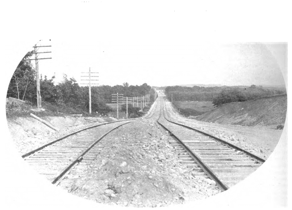 |
| Framingham Boulevard, Looking Toward Boston, With 20-Ft. Carriage Way at One Side |
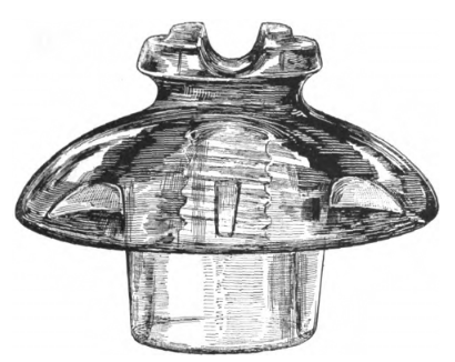
On the large Newton poles centers of cross arms are placed 29 ins. above the brackets, and two 30-in. braces are used. The cross arms are 33 ins. x 43 ins. x 6 ft. long. The transmission insulators are of C. S. Knowles' new pattern, type "J. G.," of emerald glass, mounted on 1-in. locust pins. These insulators are about 6 ins. in extreme diameter, and are specially designed to carry a working voltage of about 25,000, if necessary. Each insulator weighs 2 lbs., and is guaranteed to operate satisfactorily at considerably over the line voltage.
The power supply of the road is to be derived from at large power station, located in Framingham, which has sufficient extending capacity ultimately to provide all the power required by all the cars operating between Boston and Worcester. It is probable that several other lines than those directly related to the Boston & Worcester will be thus supplied with power in the near future. Sub-stations are located at Westboro, Marlboro and Wellesley Hills.
Current is generated in the Framingham power station at 13,200 volts, and transmitted as follows: One 3-phase circuit of No. 2 copper, 11.63 miles to Westboro, sub-station No. 1 ; one 3-phase circuit of No. 2 copper, 8.23miles, to Marlboro, sub-station No. 3; one 3-phase circuit of No. 000, 9.96 miles , to Wellesley Hills, sub-station No.2. It is also probable that the Waltham Street Railway, and possibly some of the lines of the Boston & Suburban Street Railway Company will be supplied with power generated at Framingham, so that a single 3-phase line of No.2 copper, 7.53 miles long, will be run from the Wellesley Hills sub-station to sub-station No. 4, so-called, at Waltham.
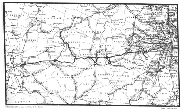 |
| Map Showing Route of Boston and Worcester Railway |
The low potential distribution is entirely made up of No. 0000 B. & S. copper cable. From the power station in Framingham to the Westboro sub-station runs a feeder 11.63 miles long, supplemented near Westboro by 4 miles of No. 0000 in parallel with it. There is also a line 8.53 miles long from the Framingham power house to the Marlboro sub-station, with an additional 4 miles of No. 0000 feeder extending to Hudson.
From Westboro sub-station to Lake Quinsigamond, Worcester, runs a similar feeder, 5.81 miles long, and this is supplemented by 3.5 miles of No. 0000 feeder running west from Northboro in parallel with the first. From Framingham to Natick runs 2.5 miles of feeder, with another line, 9.96 miles long, to the Wellesley Hills sub-station. A feeder, 7.53 miles long, runs from the latter sub-station to the Waltham sub-station, which is operated by the Waltham street railway system . East of Wellesley Hills a feeder, 4.55 miles long, runs from the sub-station toward Brookline.
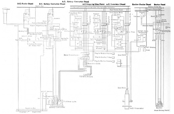 |
| System of Power Distribution |
The Framingham power station is located on the banks of the Sudbury River, where a sufficient supply of good water for feeding boilers and condensers is available, and an auxiliary supply will also be obtained from the town water service mains. The location of the station is nearly central with the line of the railway between Boston and Worcester. The plant is connected with the New York, New Haven & Hartford Railroad by a spur track leading into the property, which will enable quick and easy deliveries of coal to a bin situated directly behind the boiler room, and arranged to feed, by gravity, directly in front of the boiler room doors. The bin capacity will probably be about 1000 tons. The power station stack is of brick, and is 185 ft. high, with a core of 8 ft. in diameter through its entire height.
The station building is a handsome structure of red brick with granite trimmings, measuring 122 ft. 8 ins. long, by 106 ft. 0 ins. wide, and divided by one main wall into an engine room and basement and a boiler room. The former is a high, well-lighted and ventilated room with a basement, which is in reality the first story, being on the level of the yard outside. The distance from floor to floor is 12 ft., and in this basement are located the heaters, condensers and all large piping connecting the engines with the boiler room piping, as well as the air chambers under the transformers, the toilets, men's room, etc. In this connection it might be mentioned that no piping will be seen in the engine room above its floor line. Stairs provided with "Universal" tread connect the basement with the engine room floor, and an open well in the rear of the engines gives a view of the air pumps and condensers. Heaters were furnished by the Whitlock Coil & Pipe Company, of New Haven, Conn., and condensers by the International Steam Pump Company. Extra heavy piping is employed throughout, and no duplicate piping was installed.
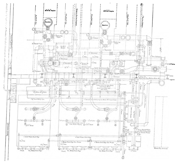 |
| General Plan of Piping in Power Station of Boston & Worcester Railway at South Framingham |
In the boiler room the main features are its excellent ventilation and lighting and general accessibility. The boilers are of the horizontal style, furnished through Thayer & Co., Boston, and made by Aultman & Taylor Company. These will be 500 hp, in one battery, and 1000 hp in the second, with space for 1000hp additional as soon as the requirements of the service demand it. Hand firing is to be employed. A Green economizer is installed, and the usual complement of pumps and heaters is to be found here. The Green economizer is situated between the present boilers and the space for the future installation, and the main smoke flues from the boilers are arranged to pass the hot gases through the economizer by a system of dampers, or by a separate by-pass into the chimney. The stack is capped with a sectional cast-iron covering and provided with a ladder and lightning rods. The section of the first35 ft. is square capped, with a granite belt, and for the remaining 155 ft . it is round, tapering with graceful lines to a slightly spreading top. Solid red brick were used in the walls, and the outer wall is separated from the inner core by an air space for its entire height. The coal bunkers are at the base of the stack.
The main generating units in the engine room at present are two in number. One of these is a Rice-Sargent horizontal cross-compound condensing engine, cylinders 24ins . x 48 ins . x 48 ins ., rated from 1500 hp to 2500 hp, according to cut-off, operating at 150 lbs. steam pressure, and direct-connected to a General Electric 1000-kw 28-pole"ATB" 3-phase 12,200-volt alternator, of the fly-wheel type, revolving at 107r. p.m. With this type of generator o engine fly-wheel is required, the revolving field being made of sufficient diameter and weight to give all the fly-wheel effect required. In other words the generator is built on the fly-wheel instead of beside it. This does away with one hub and set of spokes, and makes a simpler, neater looking unit. The fly-wheel effect of the revolving field is 81,700 lbs., at a radius of 5.42 ft. The other unit is a similar Rice-Sargent engine, cylinders 20 ins. x 40 ins x 42 ins., rated from 800 hp to 1500 hp, according to cut-off, and operating at 107 r. p. m., direct-connected to a General Electric "A T B" 28-pole, 500-kw, 13,200-volt, revolving field alternator, with a fly-wheel effect of 50,000 lbs at 4.4 ft. radius. The regulation of these engines will be by a high-speed governor in connection with an approved form of Corliss valve gearing. The governors will be capable of controlling the speed so that at full load it will not vary from that at no load by more than 1 per cent, and the instantaneous variation of speed, under any conditions of loading will not exceed 3 per cent, the instantaneous variation in this case meaning the maximum departure of the speed of the engines from the speed at which they were operating when the load was changed. The governor will be adjustable while running, so that the speed of a generator without load may be made to correspond to that of the other, carrying a full or partial load, so that one or the other may be paralleled and thrown out of service at will. Ample space is provided for the installation of a larger engine in the future. In the engine room are also two steam-driven exciter sets, each consisting of a General Electric M. P. , 6-pole, 35-kw, 305 r. p. m.,125-volt direct-current generator, direct-connected to a General Electric single-cylinder marine-type engine. There is also a motor-driven exciter of General Electric work, consisting of a 4-pole, 50-kw, 750 r. p. m., 125-volt direct-current generator, direct-connected to and mounted on a common base, with a 4-pole, 75-hp, 750 r. p. m., 350-volt form "K" induction motor.
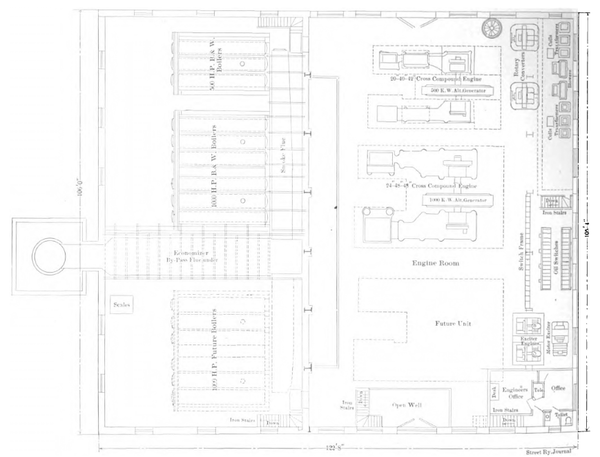 |
| Plan of Power Station |
A traveling crane of 25 tons rated capacity sweeps the entire engine room floor, resting on a steel track, supported directly upon steel columns, which pass vertically to the basement floor level. This crane was furnished by the Whiting Foundry & Machine Company, of Harvey, Ill. It was necessary to excavate to a depth of 12 ft. below the basement floor level in order to provide suitable foundations for the building and its heavy machinery. The foundations were all built of Portland cement concrete.
The frame of the building is especially heavy in steel, all roof trusses and the frame of the engine room floor being of steel construction. About 150 tons were used in this work, furnished by the American Bridge Company. Brick arches with 4 ins. of concrete covered with 1 in. of Portland cement, make up the construction of the floor. The first 6 ft. of the engine room walls are of white enamelled brick, with dado above, and the remaining wall is to be treated with cold water paint.
The chief engineer's offices are located at one end of the room, and so arranged that visitors to the station will enter only through a door leading into the basement and by a staircase leading into these offices.
The entire system of steam and water piping has been developed with the greatest care for the service required in the operation of the station. Extra heavy valves and fittings are used where live steam is carried. The Holly system of gravity drip is used to return all drip water to the boilers. The feed water can be sent through or around each of the economizers or direct from the pumps to the boilers. The exhaust from the engines is arranged with a by-pass around the main heaters, so that they can be immediately removed, if required, without shutting down any part of the main operating system. Deane and Knowles condensers of ample capacity take their injection water from the Sudbury River, by means of a well connected with the latter by a canal, provided with a screen and gate at its mouth.
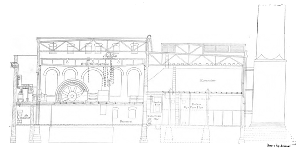 |
| Cross Section of Power Station |
The steam mains are 16 ins . in diameter, and are located at the rear of the boilers, and rest upon heavy adjustable roller brackets, about 3 ft. above the floor, making the large valves especially accessible. A 6-in . auxiliary main over this one supplies steam for all pumps, etc. All leads from the boilers are of mild steel, carefully jointed with long-turn bends wherever possible. All gate valves are the Chapman Valve Manufacturing Company's make, and globe valves are of Cody make. Cochrane separators are arresters, and nine Q. B. lightning arrester switches connected in the transmission lines as they begin in the station.
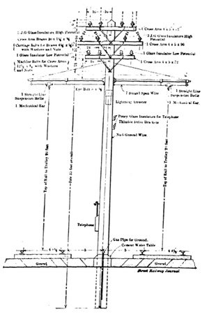 |
| Standard Overhead Line Construction |
Each of the outgoing transmission lines is equipped with a motor-driven "Form H" oil switch, of the type used in the large Manhattan and other stations in New York City, in order to make it possible to break a line-short circuit without failure, even if the capacity of the station increases several hundred per cent. The other switches are of a smaller breaking capacity and hand operated. All but the generator switches are fitted with instantaneous overload relays, making the switches serve as automatic circuit breakers, doing away with the use of fuses in the high-tension circuits.
The cables running from the switchboard are easily accessible, and the part of the building over the switch-board and its connections is in the form of a tower, into the top of which all feeder cables, etc., are brought and anchored to a cage before connecting with the main switch-board.
The power station is one of the largest planned in New England.
Combined car houses and sub-stations are being built at Westboro, Wellesley Hills and Waltham, and in addition the present street railway power station in Marlboro will be converted into a sub-station. These buildings are substantially built of red brick with steel trusses, furnished by Milliken Bros., of New York, and composition roofs. Ample pits for the cleaning, inspection and minor repairs of trucks and motors are provided, with wash basins for cleaning crews, repair shops, offices for superintendent, assistants, conductors and motormen's room, stock and boiler room. The buildings will be heated direct by steam. The Westboro car house has five tracks and two pits, about 128 ft. long each, with two smaller pits, 37 ft. long each. The generating, or rather the rotary room, of this sub-station is 27 ft. x 56 ft. The sand pit is about 22 ft. long.
| |||
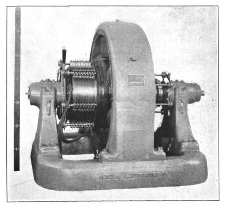
| 400-Kw Rotary Converter |
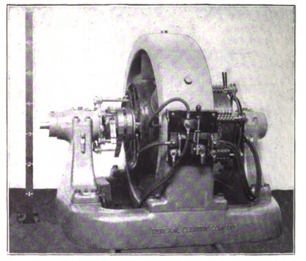
The electrical equipment of the Westboro and Marlboro sub-stations is the same in each case. After the high potential current of the transmission line has been brought into the sub-station building, it is reduced to 370 volts by six air-cooled General Electric 25-cycle, 100-kw step-down transformers, supplied with two 37.5-kw air-cooled reactive coils. There are two blower sets, each composed of a 50-in. fan, direct-connected to a General Electric M.P. 4-pole, 1-kw, 400 r. p .m., 600-volt motor, operated off the direct-current bus-bars of the sub-station, with automatic release-starting rheostat. Each sub-station has two General Electric 250-kw rotary converters, 6 poles, revolving at a speed of 500 r. p. m., and giving direct-current at 600 volts, to be fed to the trolley lines, as in the Framingham station.
The sub-station switchboards are composed in these two cases of eight panels each. There are two 1200-amp. form "A" General Eletric [sic] Electric feeder panels, two 600-volt direct-connected blower motor panels, two 300-kw alternating current rotary panels, and two 300-kw, 600-volt direct-current rotary panels. Great care was taken in all switch-boards to separate sufficiently bus-bars or wires at different potentials. The material of the switchboards is black enamelled slate.
Each converter is also equipped with a triple pole, double-throw alternating current starting switch, connected in the low-tension circuits between transformers and converter, and so connected as to switch the converter on to taps in the transformer windings, by means of which the converter can be started by alternating currents at low voltage.
In the Wellesley Hill sub-station are located six 25-cycle General Electric 145-kw air-cooled step-down trans-formers, supplying 3-phase alternating current at 370 volts to two General Electric 400-kw , 600-volt rotary converters, speed 500 r. p .m. There are two 60-kw air-cooled reactive coils, and the blower sets are two in number, composed of Buffalo fans, driven by form K, 350-volt induction motors. The Wellesley Hills switchboard has ten panels in all, made up of two 400-kw alternating current rotary panels,two400-kw direct-connected rotary panels, two alternating current rotary starting panels, two 1200-amp. form "A" feeder panels, and two 350-volt alternating current blower motor panels. The usual complement of lightning arresters and switches is provided.
| |||
| 400-Kw Rotary Converter, Showing Frame Switch |
All panels are 16 ins. wide and 7 ft. 6 ins. high. The board in the Framingham station is 26 ft. 8 ins. long. Panels are of the standard thickness of 2 ins.
The rolling stock will be composed of fifty cars, supplied by the Newburyport Car Company, of Newburyport ,Mass. All closed cars will be vestibuled, and the larger cars are 42 ft. 6 ins. over all. All cars are double-trucked and equipped with General Electric "57" motors, rated at50 hp on the one-hour basis of 75 degs. C. rise above the
surrounding air. Each motor weighs 2972 lbs., its end armature bearing commutator is 6 3/8 ins. x 2 7/8 ins., pinion end 8 3/4 ins. x 3 1/4 ins., and its armature is 14 ins. in diameter. The armature cores have thirty-three slots, there are three coils per slot, and the commutator segments are 10 1/4 ins. in diameter, with a wearing depth of 1 in. The wheel diameter is 33 ins., bringing the clearance of 3 1/2 ins. between bottom of motor frame and top of rail. There are two brushes per holder, 2 1/4 ins. x 1 3/4 ins. x 5/8 ins. All cars have single trolley, and open cars have special rattan seats ,supplied by the Haywood Bros. & Wakefield Company. Peckham trucks, of the type No. 14 B3, extra strong, are used, with axles 4 1/4 ins. in diameter. General Electric ordinary series parallel hand control is used, as it is not planned to couple up cars in trains under the multiple unit system. The seating capacity of the larger cars is seventy-five people, and the smaller cars seat sixty. These latter cars are 36 ft. over all. The cars will be equipped with Christensen air brakes.
 |
| High Tension Feeder Insulator |
Telephone lines will be run along the road, and some form of automatic signal will be used to prevent accidents. The double tracking of the line to Framingham will undoubtedly be as convenient in operation as is the working of similar lines, such as that between Albany, N. Y., and Schenectady, which is well known as a short high-speed line of the same class.
The beginning of operation of the Boston & Worcester road is awaited with much interest in eastern Massachusetts. Up to the present time the Boston & Albany Rail-road has supplied the only real rapid transit between the two cities. A few words about this road in its relations to the suburban territory and traffic near Boston maybe of interest in connection with the prospective opening of its electric competitor. It is, of course, in the passenger business that the steam road's receipts will be cut into. It is generally accepted that there has been no reduction in the steam road's fares since the middle of the last century. Last year the average passenger fare per mile on the Boston & Albany, including commutation tickets, was 1.74 cents, and the freight rate per ton mile averaged .83 cents. The gross earnings per passenger train mile were $1,569. Operating expenses were 66 per cent of gross receipts. Maintenance expenses per total train mile were: Roadbed, $.099; renewing rails, $.005; bridges, $.009 ; locomotives, $.078; passenger cars, $.085; freight cars, $.110; wages, $.304; fuel, $.128; total, $0.818. The cost of repairs per locomotive for the year was $2,182.12; per passenger car, $711.93, and per freight car, $62.73. The analysis of the annual reports of the Boston & Worcester will doubtless present many interesting features by way of comparison with the Boston& Albany methods of operation.
While it is true that extremely low commutation rates are in force on the Boston & Albany between Worcester and Boston, the daily fare being 19.7 cents each way for the 44 miles, it is also true that there are to be about twice as many runs daily on the electric road between the two cities as on the steam road, with the added pleasure of riding through country uninhabited by cinders, smoke and soft coal dust. Then again, the average time of steam trains between the two cities is not far from 1 hour 24 minutes, although several fast expresses make the distance easily in 55 minutes. It is probable that nearly all the pleasure traffic will be captured by the electric road unless a radical change in the Boston & Albany policy is made, until the limits of the Newton circuit loop line is reached. The circuit line of the Boston & Albany from the South Station to Riverside and return, via main line and Brookline, or vice versa, offers a most attractive field for electric equipment, and it is impossible to state how large a proportion of the present traffic will be diverted, but it is safe to assume that beyond Newton Upper Falls the electric competition will be severely felt. On the main line of the Boston & Albany, up to about 5 miles out, the electrics of the Boston Elevated have a large share of the suburban business, and the Boston & Worcester lies a little too far south of the main line to be felt seriously on this side of the circuit, but on part of the Brookline side of the circuit, and westward of Wellesley Hills on the main line, the influence of the Boston & Worcester line will be carefully studied by close observers of transportation methods and analysis in eastern Massachusetts.
The operation of the new line will bein charge of Superintendent A. C. Ralph, who is at present connected with the Shaw interests in Marlboro, and the electrical engineer will be M. V. Ayres, formerly with the General Electric Company in Schenectady. The construction of the entire line has been carried forward under the immediate supervision of James F. Shaw & Co., of Boston, who are also similarly interested in the building of lines between. Boston and Providence, Worcester and Hartford, etc. The board of directors of the Boston & Worcester is composed of the following gentlemen, well known in New England street railway circles: William M. Butler, Boston, president; George A. Butman, treasurer and clerk; Charles C. Peirce, of Brookline; J. J. Whipple, Boston; H. Fisher Eldredge, Portsmouth, N. H.; P. W. Sprague, Boston; Albion R. Clapp, Wellesley; A. B. Bruce, Lawrence; W. H. Trumbull, Salem; A. E. Childs, Boston; F. C. Hinds, Boston; C. H. Shippen, Milford. Thanks are due especially to Messrs. James F. Shaw, Charles C. Peirce, B. D. Sumner and E. H. Kitfield for much of the information presented in this article. The street railway map of Massachusetts is under going constant changes in these times of combination of interests, and the changes of the future in the western suburban territory outside of Boston are likely to be profoundly influenced by that potent trunk line in the electric rapid transit system — the Boston & Worcester Street Railway.

