[Trade Journal]
Publication: Street Railway Journal
New York, NY, United States
vol. 20, no. 14, p. 478-482, col. 1-2
Motive Power and Rolling Stock on the Rapid Railway
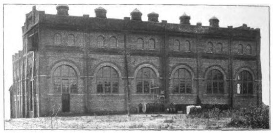
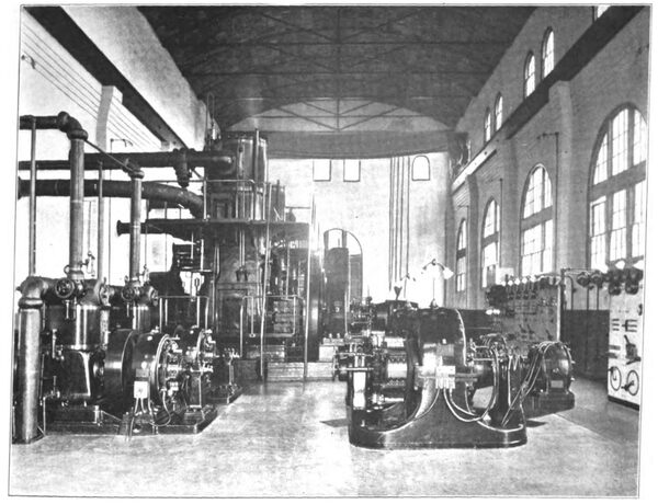
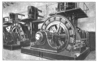
The Detroit & Port Huron Shore Line Railway Company, commonly known to the public as the Rapid Railway system, was among the first of the interurban electric roads of the country to adopt an extensive system of alternating-current distribution. The power house which generates all the electrical energy used by the Rapid Railway system is located at New Baltimore, on Lake St. Clair, close to the line of the road. The power house supplies about 110 miles of city and interurban line. The interurban lines are shown by the accompanying map, upon which also are indicated the sub-stations from which direct current is supplied to the trolley line. The power house at New Baltimore is the work of Westinghouse, Church, Kerr & Company, and bears all the familiar engineering features common to the plants erected by that company. At this power house there are three units of 500kw each. The generators are three-phase, 390-volt machines, and the engines are Westinghouse tandem compound condensing 21 1/2-in. and 37-in. x 22-in. stroke. The two exciters are 35-kw, 125-volt direct-current generators, direct connected to Westinghouse com-pound engines. In the boiler plant four Babcock & Wilcox water-tube boilers are equipped with Roney mechanical stokers. A centrifugal pump raises the water about 21 ft. for use in the Worthington jet condensers, which are located just under the boiler-room roof. Induced draft is, of course, used, there being two steam-driven draft fans, either one of which is sufficient to maintain draft for the plant. Before passing to the draft fans and the low stack, the flue gases are put through Green economizers, which reduce the temperature of the stack gases from about 520 degs. to 440 degs. A continuous record of flue-gas temperature is kept on the power-station log, which is kept daily by the engineer, reproduced herewith. The three alternating-current generators
| |||
| Exterior of Station at New Baltimore |
are connected to a common set of three-phase bus-bars through single-throw, three-pole switches. There are no circuit breakers in the generator circuits, the generator panels containing only synchronizing lamps and synchronizing plug receptacles, a three-pole switch, a double-pole field switch, a field rheostat, an alternating-current ammeter in each of the three legs, and an indicating wattmeter. From the 390-volt, three-phase bus-bars two rotary converters of 200-kw capacity each are operated directly. These supply the trolley lines near the power house. There are two sets of step-up transformers also operated from the alternating-current bus-bars. One set supplies the 16,000-volt high-tension transmission lines running north and the other set the high-tension line running south. There are, therefore, six transformers in regular service, with a seventh as reserve. Each bank of three transformers has a low-tension panel, through which the current to it passes. In this panel there are automatic circuit breakers in each leg of the circuit. From this description it will be noticed that the circuit breakers are placed only in the transformer circuits, and not in the generator circuits. The two rotary converters, which are run from the power-house bus-bars, are protected by fuses in each leg. The frequency of the alternating current in this station is 28 cycles, which is rather unusual. The high-tension lines, as indicated by the accompanying map, extend 40 miles north to Port Huron, and 21 miles south toward Detroit, as far as Roseville sub-station. The high-tension mains are all No. 1 copper wire on Locke porcelain insulators, Nos. 3 and 4. As indicated by the map, in addition to the current supplied to the trolley line from the rotary converters at New Baltimore power station, there are sub-stations at Mt. Clemens, at Roseville, at Algonac, at St. Clair, and at Port Huron. The latter supplies city lines in Port Huron. The majority of these sub-stations are equipped with two 200-kw rotary converters.
| |||
| Interior of New Baltimore Station, Rapid Railway |
The arrangement for feeding direct current from the sub-stations to the trolley lines is of interest. The trolley line is sectioned opposite each sub-station, as is customary in alternating-current transmission practice for interurban lines, and, as usual, there are two feeders leaving the direct-current bus-bars at the sub-station, one for supplying the trolley line in one direction and the other for supplying the trolley line in the other direction. Each trolley section, therefore, is fed by the sub-station at each end, so that the sub-stations can, to a certain extent, help each other in carrying the load, and as long as all the feeder-panel switches and circuit breakers are closed all the trolley-wire sections on the road are connected together. In case of short circuit on one section the feeder-panel circuit breakers in the sub-station at each end will open. The peculiar thing about the direct-current feed on the Rapid Railway system is that instead of connecting the feeders directly to the trolley line at the sub-station no tap is made to the trolley line until about a mile from the sub-station. Mr. Marshall, the chief engineer, believes that this is a very good plan, because it does not throw so great a strain on the sub-station
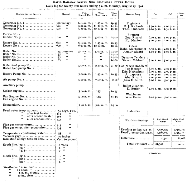 |
| Power Station Log, Rapid Railway |
machinery in case there is a ground or short circuit near the sub-station. The current that will flow in case of a short circuit is reduced somewhat by the resistance of the feed wire between the sub-station and the first trolley tap, and, even though this resistance may be small, it serves in a measure to reduce the current which may flow. After a direct-current feeder has been tapped into the trolley line about a mile from the sub-station, taps are made to the trolley line after that every twelve to fifteen poles. On the lines between Mt. Clemens and Port Huron the direct-current copper consists of two No. 00 trolley wires supplemented by a 450,000 cm feeder. From Mt. Clemens to Detroit along the Shore Line there are two No. 00 trolleys supplemented at Mt. Clemens by a 450,000-cm feeder from the Mt. Clemens sub-station and at the Detroit end by a 450,000-cm feeder run across country from the Roseville sub-station. On the Shore Line between Mt. Clemens and Detroit, where interurban traffic is the heaviest, there are two No. 00 trolleys and three No. 0000 running each direction, as indicated on the map.
| |||
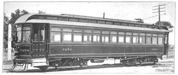
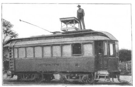
| Passenger Car, Rapid Railway |
Before the Port Huron and city lines were operated from the New Baltimore power house a good opportunity was afforded for determining the power required per car mile for interurban cars of the kind used on the Rapid Railway. Most of the cars on the Rapid Railway are geared for a maximum speed of about 45 miles per hour, some of them being four-motor equipments, and some two-motor. The four-motor equipments usually reach maximum speed sooner than the two-motor equipments, although when up to speed they run about the same. It was found that the power required per car-mile for the interurban cars as measured at the low-tension bus-bars at the power house, and which includes, therefore, the losses in step-up and step-down transformers, high-tension lines, rotary converters and direct-current feeders, was about 3 kw-hours. As to the maximum load coming upon the power house when running interurban cars alone, the following figures represent conditions as they existed part of the time before the Port Huron city lines were operated from this power house.
| |||
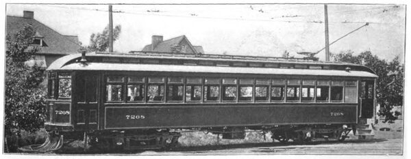
| Passenger Car, Rapid Railway |
There were in operation cars as follows:
20-ton passenger cars, four-motor equipment.. 8
21-ton passenger cars, two-motor equipment... 6
25-ton freight cars, four-motor equipment....... 3
Line construction cars ......................................2
8-ton city cars in Mt. Clemens .........................2
Total................................................................ 21
| |||
| Generator, Rapid Railway |
The output for a run of twenty hours was about 14,000 kw-hours, or an average of 700 kw. This represents an average input of 33.3 kw per car in service. Of course, for the interurban passenger cars which are in motion a greater part of the time the input per car would be considerably more than this, as the above list includes the freight cars, line construction cars and two light city cars. Indeed, the power required by the city cars is probably in the neighborhood of 15 kw average, or less than one-half that of an interurban car. With the above list of cars in operation, the maximum evening load, when nearly all the cars would be moving, was about 1384 kw, a maximum of 65.9kw per car.
 |
| Power Station Distribution System of Rapid Railway |
Several types of passenger cars are operated by this company, some of which are illustrated herewith. Those now in operation regularly have smoking compartments in the front, and are equipped to run single ended. In these various cars the hot-water heaters are placed in various positions. That preferred by W. O. Wood, general superintendent of the road, who has charge of the operation, is in the front vestibule beside the motorman. When placed in the vestibule it takes up less valuable room than in any other place in the car. The dust and ashes are kept out of the passenger compartment, and the heat is given a better distribution through the car than is possible by placing the heater in any other location. The motorman's vestibule is likely to be the coldest place in the car, as when running against a cold wind considerable cold air is sure to find its way into the vestibule. It seems but logical, therefore, that the heater should be placed in the vestibule, so that it cannot only keep the motorman warm, but will radiate the most heat from the pipes in the forward end of the car. In case there is much passenger travel the motorman has much more time to attend to the heater than does the conductor. The argument sometimes advanced that if the heater is placed in the vestibule the motorman will keep the fire too low in order to keep the vestibule from getting too hot is an argument against the type of heater used, and not against the practice of placing it in the vestibule. A heater so constructed as to radiate a large amount of heat into its immediate surroundings is not an efficient hot-water car heater.
| |||
| Construction Car |
The mileage of the motor-armature bearings is kept track of closely, and when an armature is run 20,000 miles in a set of bearings it is watched carefully, as it is known to have reached a point where it will not last a great while longer. Kalamazoo trolley wheels are used, from which a life of from 5000 to 10,000 miles is obtained, which is an excellent record for such severe interurban service. The trolley-wheel pressure on the wire is adjusted at about 35 lbs.
A car equipment of four 75-hp motors has proved the most successful, the cars being about 50 ft. over all.
All the mechanical and electrical work on the system, including power station, sub-stations and car equipments, is under the care of A. C. Marshall, chief engineer.

