[Trade Journal]
Publication: Electrical World
New York, NY, United States
p. 1139-1142, col. 1-2
Designing Insulators to Combat Fog
By S. Murray Jones
Ohio Brass Company, Mansfield, Ohio
OPERATING companies as well as manufacturers are still developing insulators of the so-called "fog type." Locations in which "fog types" have been tried are mainly along the seacoast where transmission line troubles and interruptions have occurred owing to salt spray deposits. Such troubles may occur as far as 25 miles inland, although they diminish rapidly as the line leaves the seacoast. Most outages from salt spray and other contaminating elements occur either during the night or in the early morning hours at the time 'of fogs. There is, accordingly, a. common belief that the troubles are due principally to the fog. Tests and operating data indicate, however, that fog is only a secondary cause of these troubles. In fact, the use of the term "fog type" is wrong. since in most cases the troubles are not primarily. due to fogs, but to contamination.
In most instances salt spray and fogs, fumes and foreign substances develop no unusual depreciation of insulator glaze or porcelain, but they do decrease the effective resistance of the path over the insulators and accordingly decrease their surface leakage resistance. Most deposits of salt or other foreign substances are of a hydroscopic and porous structure which facilitates condensation. Because of this fact the accumulation is rather rapid when once started. The result of this is that the wet flashover value is reduced materially. The reason for the reduction in flashover value is evident, since salt water, chemical solutions, etc., are much better conductors than ordinary rain water and shunt out certain portions of the porcelain., decreasing the effective length of insulation and consequently reducing the surface leakage resistance. This also tends to make an arc that clings to the surface of the insulator rather than the desirable "free arc" away from the porcelain surface, as is the case with a clean unit of proper design. The dry flashover value at low humidities is not very different for clean or dirty units. At high humidities, especially those approaching saturation or fog conditions, the reduction is considerable, as shown in Fig. l.
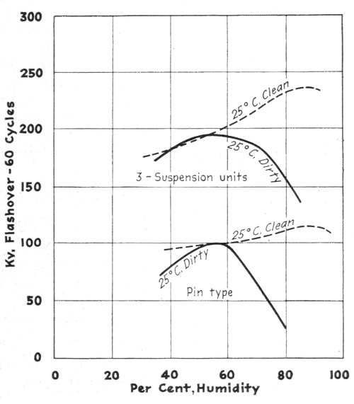 |
| Fig. 1 - Humidity Accentuates Weakness of Dirty Insulators |
Various methods of comparing different insulators to determine their adaptability under conditions of fog and dirt have been attempted. Most of these have neglected to take into consideration all of the important factor. Engineers frequently use the leakage distance of different insulators or the surface area of the porcelain, combined with the guaranteed flashover values-wet and dry-as a basis for comparison. These factors do not consider the complete insulator characteristics. As the surface of an insulator becomes moist or contaminated flashover voltage is reduced. This is due to a change in the surface resistance and the electrostatic capacity. In most designs the electrostatic capacity is affected only slightly and the increased leakage current and reduction in flashover voltage are due to the decrease in surface resistance. If the width were constant, then the resistance would be equal to the specific resistance of a unit length, times the length or leakage distance; however, in practically all insulators the width is not constant.
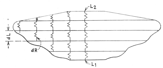 |
| Fig. 2 - Width of Leakage Path Must Be Considered. the Surface of Any Insulator, Either Pin-Type or Suspension, Has An Appreciable Width of Porcelain in Comparison With the Length of Leakage Path. the Surface Leakage Resistance is Composed of A Multiplicity of Path in Series and Parallel. |
Assuming the exposed porcelain surface to have a constant specific resistance per inch square and to be equivalent to an' infinite number of small resistances, then the surface leakage resistance may be defined as the summation of these resistances from cap or tie wire groove to pin of a single insulator.
The exact equation has been obtained for a typical 10-in. suspension unit and the surface leakage resistance as obtained from it checked against an approximate method. The values obtained from the approximate method were within 3.5 per cent of those using the true equation; consequently, since errors in obtaining insulator dimensions and manufacturing tolerances are within this limit, the approximate method suffices for a comparison.
Suspension string length a factor
This method of comparison is usually sufficient for pin-type insulators, but for suspension units another factor is quite essential. The string length or section length (S in Fig. 3) is important, since it is desired to obtain the maximum insulation in a given space, thus making tower heights a minimum. Consequently, for suspension units the surface leakage resistance per inch of section length should be used.
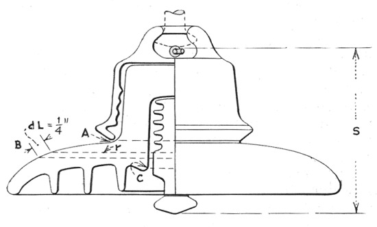 |
| Fig. 3 - Computing Surface Leakage Resistance. |
The surface leakage resistance of an insulator may be obtained approximately from a full-scale print showing the cross-section of the insulator. The leakage distance ABC should be marked off in 1/4-in. sections and the radius measured at each of these points. The surface leakage resistance of the entire unit is therefore the summation of the resistances of each of the 1/4-in. sections. If the specific resistance is assumed to be the same for all insulators and the leakage distance for each of them to be compared is divided in 1/4-in. divisions, then the surface leakage resistance factor is the sum of the reciprocals of the radii measured at each 1/4-in. division of the leakage distance. If a table of reciprocals is available, the summation becomes relatively simple, the radii being measured from a print and tabulated, the reciprocals obtained from the table and added together.]
The operating engineer, in addition to obtaining the maximum amount of insulation, or surface leakage resistance, is interested in its cost. Thus for pin-type insulators the practical basis of comparison is: Surface leakage resistance divided by cost of insulator, and for suspension insulators: Surface leakage resistance divided by (section length X cost of insulator).
These factors and methods of comparing insulator all assume that the insulator, when suspended in air, will flash over rather than puncture. Most insulators of good design will do this, but if not, then another factor, the thickness of the dielectric, must be used.
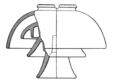
In addition to surface leakage resistance, comparisons of other factors must be considered, particularly the design characteristics and their suitability for the particular contaminating condition. Their general design must also be considered, since in some instances insulators with deeply grooved sections have been designed (similar to Fig. 4), which, when improperly proportioned, may produce overstress at the edges, when either clean or dirty, thus reducing the flashover value. Overstressing of insulators is also a source of radio troubles. The necessity of eliminating and reducing overstress, particularly on fog-type units, is important, since tests on charged and uncharged insulators subjected to dirt or other foreign substances indicate that a charged insulator becomes dirty much more rapidly than an uncharged one, the tendency being to accumulate deposits at points of overstress or points of strongest electrostatic field. One author has attributed the reason for the more rapid accumulation at the point of overstress as being due to the electrical wind. It has long been known that certain chemical processes made use of electrostatic precipitation to remove impurities from the air and break them down into nitrous solutions forming a strongly adhesive substance which cannot be removed by washing and ordinary cleaning methods, steel wool being necessary in some cases.
 |
| Fig. 4 - An Example of Overstressed Insulator. Sharp Edges and Drip Grooves Result in Overstress, Flashover and Radio Interference. |
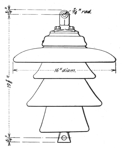
On the higher-voltage pin-type lines a satisfactory solution for fog troubles may be obtained by increasing the amount of insulation through changing the line to suspension insulator construction. Where, because of limited clearances, conversion to suspension units is impossible, the use of an assembly of two pin types in tandem might solve the problem. Pin-type design, and consequently tandems, if properly designed, have longer leakage path and more surface leakage resistance per inch of height than suspensions per inch of section length. For the lower-voltage lines certain insulators, commonly referred to as "cement-hood" types (shown in Fig. 5), are in most cases satisfactory.
 |
| Fig. 5 - Cement-Hood Fog-Type Insulator for Lower Voltage |
As has been previously mentioned, the voltage per unit has a considerable effect on the surface deposit: therefore, on suspension lines with relatively short strings the short-spaced 4-3/4-in. or 5-in. unit is of particular advantage, owing to the lower unit stress on individual insulators when compared on a string length basis. Also, it will be found that the surface leakage resistance per insulator string for strings of the same length of long- or short-spaced units will show higher values for the short-spaced units.
Adapting pin design to suspension use
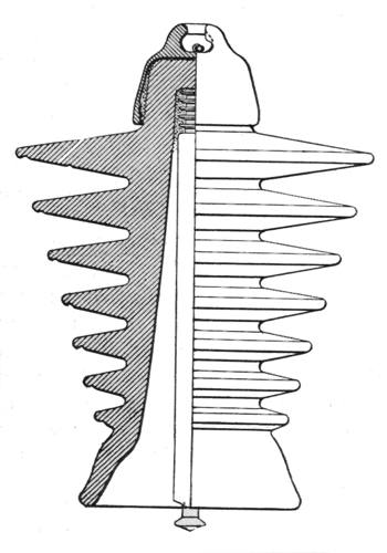
Where clearances are limited a pin-type unit converted for suspension operation, such as is shown in Fig. 6, has in many cases proved to be satisfactory.
A string made up of the units shown in Fig. 6 will provide a maximum surface resistance and leakage path per inch of string length and is constructed so that drip water does not short-circuit any sections of the insulator -a common occurrence in some of the present corrugated types.
 |
| Fig. 6 - Pin-Type Insulator Converted to Suspension Form to Meet Fog Conditions |
Where long strings of suspension units are used, as on the higher-voltage lines, flashovers may occur from fog alone. Where dense fogs exist it may be that the units are wet and dripping water most of the time. In such cases the wet flashover of the string may be increased by breaking up the drip water through inserting a few units of larger diameter, mixing them in the string.
Quite naturally, the production of specially designed insulators is relatively low when compared to that of the standard 10-in. disk. Consequently, the cost of such units is high when compared on a unit basis or per inch of leakage distance or surface leakage resistance.
An engineering comparison indicates that the most insulation, as measured by surface leakage resistance, per dollar of investment can be obtained by the use of the standard short-spaced 10-in. disk, there being a few exceptions for special locations.
Cleaning period depends on conditions
The length of time which it takes for a damaging deposit to take place on insulators is so variable and so dependent on the location of the insulators and the contaminating substances that no definite rule can be given for cleaning them. This previous statement intimates that cleaning is necessary, and most operating companies have found that they cannot economically install sufficient insulation at some locations to reduce flashovers to a minimum without incurring the necessity of periodic cleaning. In every case there is an economic balance to be found between the cost of additional insulation and a reduced number of cleaning periods and the cost of reduced insulation and an increased number of cleaning periods.
In cases where the deposit is not especially adhesive and a water of high resistance is available, cleaning may be done from an ordinary hose with the lines energized. Where this is possible, a heavy stream of water is necessary. A small stream of water would merely tend to wash the particles to one portion of the porcelain surface and might produce a flashover by concentrating the foreign particles in a line at the edge of the stream.
Most cleaning must be done with the line or equipment dead, and the insulation must be carefully wiped to prevent a residue of particles along certain portions of the insulation which will cause flashover when the circuit is recharged.
Here is an example of the difference in practices of operating companies in cleaning insulators: One company has established a routine of cleaning its units once a year. It uses a combination of No.2 steel wool and rags for cleaning, which is done with the line dead. Another company has used carbon-tetrachloride with success. A company on the Eastern seaboard, a good many of whose lines traverse salt marshes and are subjected to smoke and chemical fumes, makes a practice of cleaning suspension insulators every three months.
In most cases, owing to the better protection of station apparatus, it is necessary only to clean such insulators perhaps half as often as line insulators. Where the reverse is true, installations using spray nozzles effectively placed have been made. This permits a rigid washing schedule without interference with operation.
One investigator who has done considerable valuable testing of various proposed fog types concludes that "there is no virtue in any particular shape or design except as it provides surface leakage resistance." In addition, it is well to remember that the design should be considered and studied to determine the possibility of overstress during normal or abnormal operating conditions. Assuming that the units would 110t overstress, perhaps a better yardstick to measure the insulation would be the value of surface leakage resistance per inch of insulator section length, per dollar investment.
With the application of special units or additional insulation on lines or buses, particular attention must be given to provide proper lightning arresters, or protective gaps, to prevent damage to station transformers and other station apparatus.
Other factors should be considered equally in the proportioning of insulation or location of lightning arresters or protective gaps. The type of suspension insulator is important. The advantages of the short-section length, 10-in. diameter, ball-and-socket type, are several. There is less tendency for corona discharges from sharp corners and points, which may occur on other designs such as clevis units or units with longer section length but with no increase in diameter. The ball-and-socket unit, being rotatable, where the clevis is not, certainly has the advantage where cleaning must be done.
The selection of proper hardware is important. It must be free from corrosion and of such design that corona discharges are a minimum and voltage grading effect on the string a maximum. Poorly designed clamps having points facilitating corona formation not only reduce the flashover value of the string but because of the electric wind effect will attract foreign particles to them and to the insulators. Corona streamers from cotter keys and pins and other points of high stress are a constant source of radio interference. In some localities this has been a real consideration in the selection of insulation.
In general, then, the recommendations are to provide additional insulation in locations which are subject to salt spray, fogs and conditions of dirt, using on pin-type lines either tandem assemblies of standard pin-type units or those of the cement-hood type, and using close-spaced units on the medium- and high-voltage suspension lines (the number of units to be determined experimentally from operating practice) and in some instances mixed strings of large and standard 10-in. diameter suspension units.
