[Trade Journal]
Publication: The Journal of Electricity, Power and Gas
San Francisco, CA, United States
vol. 15, no. 4, p. 154-155, col. 1-2
A HIGH POTENTIAL LABORATORY
THE Locke Insulator Manufacturing Company has recently added to its equipment a laboratory for electrical and electro-chemical research along the special lines required for a positive and accurate development of high potential insula- tors, it being the intention to make a more thorough study than has before been attempted of insulating materials for extremely high potentials and of insulator design.
The laboratory is full fire-proof construction measuring twenty feet by forty-eight feet in size. The foundations and floor are of heavy concrete, designed to carry the heavy machinery without communicating vibrations to any delicate apparatus. The electrical equipment includes a transformer with a guaranteed capacity of 200 kilowatts at 300,000 volts. It is of the core type, with approximately ten inches by ten inches cross section of iron and has a primary wound for 1100 volts, made up of four wires in parallel, allowing of some flexibility in connection. The secondary consists of approximately forty-two miles of No. 26 wire, which, under oil, will carry 100 percent. overload for considerable periods of time and at an overload potential of 400,000 volts this transformer is by far the most powerful electrical testing equipment in present use. The secondary winding is divided into two parts, which can be connected in parallel or series, giving full loads at low potentials.
| |||
| High Potential Transformer and Motor-Generator Set |
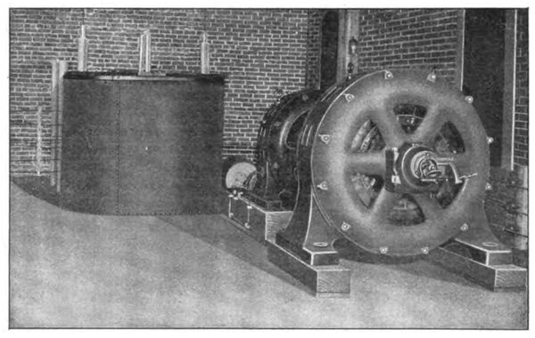
Current for the primary of the transformer is provided by a motor-generator set, power for which is obtained from a local transmission line. The set consists of a 440-volt, three-phase, twenty-five-cycle, 200-kilowatt induction motor, direct-connected by flexible coupling to a sixty-cycle, 1100-volt, single-phase generator of similar capacity. For purposes of experimentation or for special commercial test requirements, higher or lower frequency is obtained by belt connection, using various sizes of pulleys. The controlling switches for the generating set are located on a slate board placed so that the operator can overlook any test being carried on in the commercial testing room nearby. Ordinary controlling switches and rheostats together with instruments are located on this board.
To facilitate measurements of secondary voltages a spark gap, adjustable by hand, is provided with a scale calibrated to 480,000 volts, enabling test of any material to be made. For more accurate measurement of the high voltages a secondary voltmeter has been installed. This instrument, submerged in oil, transfers its readings by means of a mirror to a calibrated scale, which is read by means of a telescope. The very small secondary currents are measured by means of an inclined coil instrument inserted at the point of earth potential of the secondary winding.
| |||
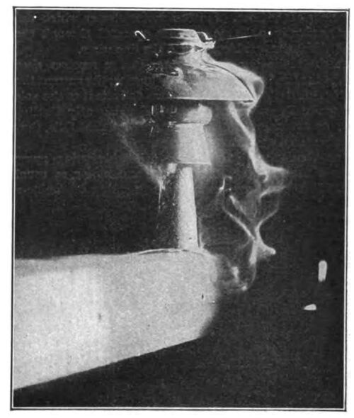
| No. 307 Insulator on Metal Pin and Cross-Arm, Arcing to Cross-Arm at 40,000 Volts, Under Rain Test. Precipitation 3-4 Inches Per Minute |
Extending some distance from the laboratory is an experimental pole line of standard poles and cross-arms adapted to receive any style of pins or insulators, whose distances apart may be varied.
A simple form of dynamometer provides facilities for the testing of tensile and crushing strength of insulators and insulating materials. In order to study very refractory substances an electric furnace, capable of absorbing 200 kilowatts, is provided, for the ceramic and electrical development of insulator design and manufacturing are so closely allied that the two lines of investigation are maintained in close co-operation.
The lack of a definite understanding of the methods of testing insulators and high voltage porcelain by some of the users or prospective users of this material, has prompted the Locke Insulator Manufacturing Company, in its recent catalogue No. 8, entitled The Insulator Book, to describe the several plans employed, which are as follows:
The standard duration of all tests is one-half minute at full potential.
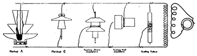
Method A is the usual method of test for either one piece or multi-part insulators. The plan consists in immersing the head of the insulator in water up to the middle of the side wire groove and filling the pinhole with water to the depth of the threading. The connections are made as illustrated. Insulators shipped knocked down are tested with the parts assembled in proper relationship; insulators shipped cemented are tested after cementing.
Method B is a special test for multi-part insulators and consists in separately testing each piece, exactly the same as the whole is tested in Method A. Method C is a dry test and is a test of the whole insulator, whether one piece or multi-part.
 |
Special shapes often necessitate special applications of these methods and below is given the manner of applying tests for products varying in form from ordinary insulators. The voltage is always applied at points of strain under actual use.
Strain insulators are tested (Method C) by using a metal tube passed through the insulator as one terminal and a chain or wire around the wire groove as the other terminal. Special strain insulators are tested by applying voltage between top and bottom castings.
Wall insulators are tested (Method C) by passing a metal rod through the insulator and applying a metal strap around the outside at the point provided for the panel.
Straight tubes are wrapped at their middle with tin foil for one-third their lengths and passing a metal rod through the holes (Method C).
 |
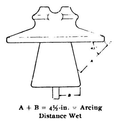
The wet sparking distance is obtained as per the accompanying illustration, which shows the method of measuring distance on a Locke No, 408A insulator. The conditions assumed for these measurements are: The pin is one inch in diameter at the bottom of the insulator and high enough so that the spark will jump to the pin and not to the cross-arm, except for strain insulators, which are measured from the edge of the lower petticoat vertically to the cross-arm, The angle of precipitation is 45 degrees from the vertical.
Below is given a table of sparking distances in air between sharp needle points, as employed in testing.
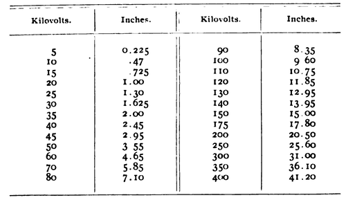 |
