[Trade Journal]
Publication: Electrical Review
New York, NY, United States
vol. 51, no. 3, p. 94-96, col. 1-3
SOME NEW METHODS IN HIGH-TENSION LINE CONSTRUCTION. (1)
BY H. W. BUCK.
The great economies in the cost of generating power which have been obtained in the large steam turbine stations and hydroelectric plants are leading to the general abandonment of small generating stations and the increase in transmission distances in order to distribute power over a large territory. In other words, 100,000 horse-power can be generated in one station and transmitted 100 miles cheaper than it can be generated and distributed from ten 10,000-horse-power stations near the centre of load. On account of this tendency toward the concentration of generating units, the overhead transmission line has assumed a position of great importance in electrical installations, and the same permanency and reliability is demanded of it as of the generating station itself. The wooden pole line of the past has been practically abandoned and steel construction has been substituted.
The long distances required for many of the modern lines, the large amounts of power to be transmitted, and the very high price of copper and aluminumall have combined to force up the transmission voltage to the highest practicable limit. In consequence the demand for high-voltage overhead line insulators has outgrown the present standard practice, and some new systems will have to be introduced to meet the new conditions.
The method of line construction here described has been developed by the writer and E. M. Hewlett and is believed to offer a means of operating lines safely at higher potentials than is practicable with insulators of the pin and petticoat type.
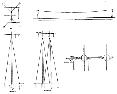 |
| Fig. 1 -- Diagrammatic Arrangement of One Circuit. |
Fig. 1 illustrates in a diagrammatic way the arrangements for one circuit. The tower supports shown here are those which were used merely for experimental work and need not be considered as a commercial design. Each span is dead-ended at each support as shown, through a series of insulating units which in this case are plain discs connected together with steel links. The various spans are then electrically connected by jumpers hung below the insulators. The insulators are directly attached to the cross-arms, eliminating all pins. The number of discs linked together in series depends upon the line voltage, the discs themselves being identical for all voltages.
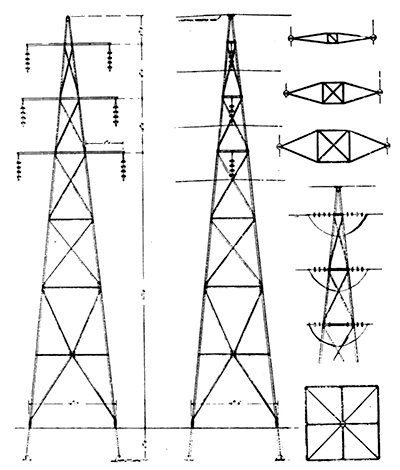 |
| Fig. 2 -- Design of 100,000-Voit, Two-Circuit Line. |
Fig. 2 illustrates a design for a 100,000-volt two-circuit line which is soon to be constructed for transmitting 50,000 horse-power 165 miles. The spans in this case will range from 500 to 1,000 feet in length. Here the line is suspended below the cross-arm on most of the towers. The lines will be dead-ended with jumper connection as shown only at angles and on tangents at about every fifth tower. This dead-ending will be for the purpose of stopping any creeping of conductors on the line as a whole, to check the transmission of longitudinal waves along the conductors due to wind, and on curves to take the side stress of the conductor due to change in direction. In this installation the lines will not be triangulated, but at suitable intervals along the lines the conductors will be transposed so as to balance up effects of mutual static and magnetic induction. Special cross-arms will be installed at transposition towers.
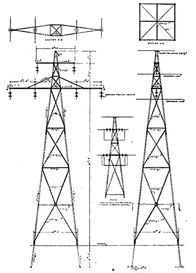 |
| Fig. 3 -- 80,000-Volt Two-Circuit Line. |
Fig. 3 illustrates another design for a two-circuit line which is to be built for 80,000-volt operation. The spans in this case will range from 300 to 400 feet and the conductors will have an approximate triangular relation. The conductors will be suspended by a series of insulators from the cross-arms as in Fig. 2 with occasional rigid attachment, for the reasons given above.
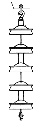 |
| Fig. 4 -- Assembly of Insulator for Suspension Under Cross-Arm. |
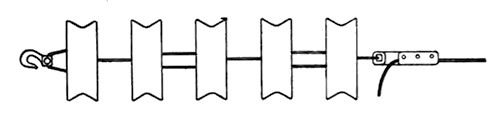 |
| Fig. 5 -- Assembly of Insulator for Dead-Ending. |
Fig. 4 shows a method of assembly of the insulators for suspension under a cross-arm. Fig. 5 illustrates a method of assembly where spans are dead-ended at the cross-arm with jumper connection.
The advantages of this construction, which might be termed series unit insulation, over the pin and petticoat type may be summarized as follows:
1. With the standard type of pin insulator now used the difficulties of construction increase very rapidly at the higher voltages. The cost of insulator for a given margin of safety increases for voltages above 60,000 nearly as the cube of the increase in voltage. Either very large petticoat diameters must be used, or very high insulators with many petticoats. In either case the manufacture of the porcelain parts is a difficult and expensive matter, and with the long pin necessary the mechanical stresses from the line on insulator, pin, and cross-arm are objectionable. With the series unit system here proposed the cost of insulator progresses only in direct proportion to the increase in voltage, the only change being in the number of units in series. There is practically no limit to the degree of insulation obtainable.
2. One of the most difficult elements of design in a transmission tower where long pins and petticoat insulators are used is to obtain a cross-arm which will resist the torsional stresses due to the leverage of the pin. With the pin entirely eliminated, the stresses are directly applied to the cross-arm; this cheapens the construction of the tower.
3. In the arrangements shown where the insulating units are attached on either side of the cross-arm, taking the full tension in the line with jumper connection between spans, the insulation can be increased indefinitely by adding discs in series without increasing the space occupied on the tower.
4. Where each span is dead-ended, as in (3), all faces of the insulating units are exposed to the cleansing action of the rain, so that dirt cannot accumulate thereon. This arrangement also prevents the dripping water from forming electrical communication between units as occurs from one petticoat to another in the pin type of insulator.
5. A standard insulating unit can be adopted for all voltages, the only variation being in the number linked in series. This simplifies the manufacturing problem.
6. If any insulating unit becomes dam aged or completely shattered the insulation of the remainder is not affected. The damaged unit can be replaced without the necessity of renewing the whole.
7. If a tower is directly struck by lightning the cross-arms will be likely to make the discharge, since they are above the lines, whereas in the pin type of insulator the line is usually the highest point.
8. In long-span installations where the conductor at each end of the span is tied fast to an insulator mounted on a pin, experience has shown that crystallization is apt to take place in the conductor at the tie, due to its rigidity at that point and the vibrations in the span. This frequently results in breakage of the conductor. The flexible connection between conductor and cross-arm afforded by the series of insulators should reduce this tendency to crystallization, and should therefore permit spans of any length to be used without further precautions against this action.
Fears may be expressed that with the conductor suspended under the cross-arm series swinging to and fro might take place. From numerous observations it is believed that no such swinging will occur. Long aerial spans under wind pressure take a permanent and steady deflection throughout the span proportional to the average wind velocity along the span, and no indications have been observed of long spans responding to so-called gusts. The towers shown in this paper are designed so that the conductor can safely be deflected by the wind about sixty degrees on either side of the neutral position.
Insulators of a great many forms have been built and tested, but the one which gives the best results electrically and mechanically is the link type developed by Mr. Hewlett and having the grooved or fish-tail periphery. Four of these in series is sufficient for 100,000-volt operation with a liberal factor of safety.
A very important element in this construction is of course the methods of fastening the insulating units together and attaching them to the line and cross-arms. This can be accomplished in many ways and several methods have already been worked out, but these details are beyond the scope of this paper. Further experience in practical line construction and operation under this system will demonstrate the best methods of installation and attachment.
(1) A paper presented at the twenty-fourth annual convention of the American Institute of Electrical Engineers, Niagara Falls, N. Y., June 26, 1907.
