[Trade Journal]
Publication: Street Railway Journal
Chicago, IL, United States
vol. 28, no. 15, p. 642-660, col. 1-2
THE GENERATION AND TRANSMISSION OF POWER
A few years back, when most of the interurban roads were promoted and built by separate groups of promoters, the practice was to build a separate power station for each road. Individual engineers followed their own ideas as to designs of stations and methods of generating and transmitting current, and the result of these numerous individual and disconnected efforts was that up to a year or two ago there were in Ohio a large number of comparatively small power stations, each supplying in its own way a single property regardless of conditions nearby.
Direct-current generation and transmission were used on the majority of the earlier lines, and as late as four or five years ago direct current was advocated and used on new roads of less than 30 to 35 miles. As a matter of fact, the direct-current scheme of transmission still has many advocates among the operators of the shorter lines, who, while they are paying somewhat more per kw for current generated and have heavy investments in copper, which must some day be replaced, yet it cannot be denied they enjoy a comfortable feeling of security in times of high winds and severe storms, and they are inclined to view with sympathetic amusement the high tension and sub-station troubles of their larger neighbors.
Several of the earlier roads in Ohio using alternating current transmission employed a potential of 10,000 to 13,000 volts, but later years have seen a growing tendency towards larger stations, larger units and higher voltages. Six years ago witnessed the building of the Toledo, Fremont & Norwalk Railway, now a part of the Lake Shore Electric Railway, with a 2000-kw station, 65 miles of road and 16,500 volts transmission. This was the most ambitions interurban project attempted in the district up to that time, and the layout represented the highest developments in the art. A little later came the Stark Electric and the Cleveland & Southwestern, with 22,000 volts and 24,000 volts transmission, respectively. Then came the Western Ohio with an 80-mile line, 3300-kw station and 33,000-volt transmission lines. This high potential was looked upon with some skepticism at the time, but it has since been adopted by the Toledo Urban & Interurban, the Fort Wayne, Van Wert & Lima, Cincinnati Northern, Columbus, Delaware & Marion and the Cincinnati & Columbus.
The consolidation of interests and the grouping of systems which have been going on during the past two or three years have led to the abandonment of many of the smaller stations and the increasing of capacities of the larger ones, enabling power to be furnished over a number of connecting links from a single station.
The economy of large plants and the advantages of centralization of power have become generally recognized and there are several small roads in the district that are buying their power at a flat rate instead of producing it themselves. Thus, the Lake Shore Electric supplies the Sandusky, Norwalk & Mansfield; the Western Ohio supplies the Wort Wayne, Van Wert & Lima; and the Springfield, Troy & Piqua supplies the Springfield & Xenia and Springfield & South Charleston.
The St. Mary's power station of the Western Ohio takes care of 177 miles of road. The Cleveland & Southwestern, with 135 miles of road, has a single station, and it is the intention to add 86 miles to its load. The Medway power station of the Indiana, Columbus & Eastern supplies about 165 miles, and a considerable mileage will be added to this. The Schoepf syndicate, in completing its system from Cincinnati to Toledo, plans to supply power with three and possibly two power stations, while its line from Indianapolis through Dayton and Columbus to Zanesville will eventually be taken care of by either two or three stations. In view of the centralization and consolidation plans now under way, it is quite possible that five years will see 3000 miles of interurban roads in Ohio operated from ten and possibly fewer power stations where at present there are fifty interurban stations in the State.
 |
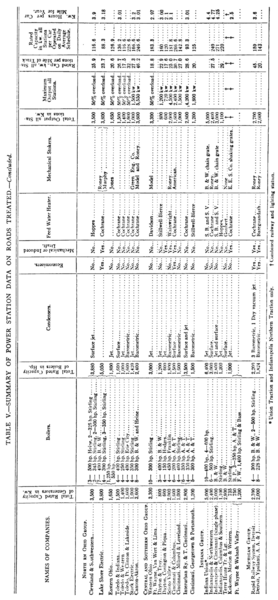 |
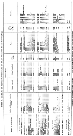
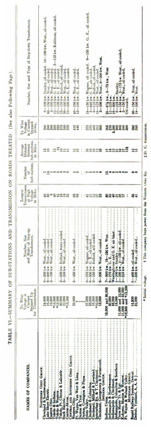
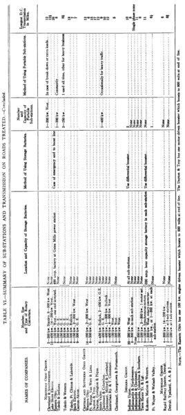
Of seventeen roads in Ohio, three still use the direct current system transmission. These three are among the smaller systems, and are independently owned and operated. One large road rents its power, while the others employ transmission voltages ranging from 10,000 to 33,000 volts. Eight generate at low voltage alternating current and step-up to the desired transmission voltage. Five generate at the high voltage and transmit without the use of step-up transformers. A potential of 13,500 volts has been considered the maximum voltage at which current should be generated, but the Lake Shore Electric has one large unit generating at 16,500 volts. The roads using the higher voltages generate at a low voltage, usually about 400, and then step-up. The longest transmission at this voltage is that of the Western Ohio, which transmits 95 miles from the station. The Lake Shore Electric supplies about 225 miles of road from its two stations. This line has a single stretch of 120 miles, and its stations, which are approximately the same size, are located at suitable distances from the ends of the line to distribute the loads between the two stations to best advantage. This company believes that two generating stations are better than one for a road of this length. The transmission lines are all tied in together and one station can assist the other in cases of emergency, even to the extent of handling the entire load if necessary. Of course, under normal conditions each station takes care of its half of the load, and the longest transmission is not more than 35 miles on the main line. The Western Ohio has its St. Mary's station practically in the center of its system, with lines radiating in four directions. The Cleveland & Southwestern station at Elyria is also well centered, transmission lines extending in three directions.
Sizes of units have increased with the growth of stations. In the earlier stations the 500-hp engine was looked upon as the most economical size. Later, in providing for additional equipments, many of the roads installed 1000-hp units instead of two 500-hp, while in the new power houses on roads of 60 to 75 miles, two 1000-hp units have been selected. New and additional equipments of more recent date have consisted of 1250-hp engines in the cases of the Cincinnati & Columbus and the Toledo, Port Clinton & Lakeside, 1500 hp for the Scioto Valley and 1600-hp engines in the cases of the Lake Shore Electric and the Columbus, Buckeye Lake & Newark.
 |
| Map of Ohio and Indiana, Showing Schoepf Properties. |
Steam turbines have been installed to some extent, and what are said to have been the first turbines used on electric roads were installed in Ohio. The first large installation of Westing-house-Parsons turbines was that of the Cleveland & Southwestern, which has had two 1250-kw units in use for more than three years. One of these turbines commenced operation Dec. 20, 1903, and the other was started Aug. 4, 1904. The station also has two large direct-current reciprocating units, which take steam from the same steam lines and supply to common bus-bars. On several eight-hour tests with the turbines running alone, the fuel consumption has been 3 lbs. of coal per kw-hour. On ten-hour tests, with one engine and one turbine running, the fuel consumption was 3.8 lbs., while for a twenty-four-hour run, with all machines in service, the consumption was 4.25 lbs. per kw-hour. There has been no opportunity for making tests of the fuel consumption over a period of twenty-four hours with turbines alone in service. Under average conditions the station generates current at about 5-1/2 mills per kw-hour. The two 1250-kw turbines occupy one end of the engine room in the station, while the other end is occupied by the two 500-kw reciprocating engines, and there is space in the turbine end for a third unit.
The Canton Akron Railway Company has a 2000-kw Curtis turbine which has been in service about six months. The advantage of economy in space is particularly marked in this installation, as the machine was placed between two other machines without enlarging the station, which would not have accommodated another reciprocating unit, and the capacity of the station was increased from 1600 kw to 2600 kw by the new machine. The cost of current at this station is less than 4%y mills per kw-hour. On one occasion the turbine carried the entire load of the system for eight days without assistance.
The Northern Ohio Traction & Light Company has a 500-volt, direct-current Curtis turbine at Akron, and is installing a large a. c. turbo unit at the present time.
The Columbus, Delaware & Marion Railway has a 2000-kw Curtis turbine in service and is installing a second one.
The Ohio Central Traction Company has a 150-kw De-Laval turbine, which has been in service for three years.
The Lake Shore Electric Railway is installing a 2000-kw Parsons turbine in its Beach Park station, and plans are being laid to install a similar unit in its Fremont station.
Water-tube boilers of the Stirling or B. & W. type predominate. The tendency is towards the use of larger units, in order to economize space and labor. In the later installations 450 and 500-hp units are the popular sizes. Up to a year or so ago very few plants in the district were equipped with stokers, probably because most of the roads were built with limited investment. As lines have been extended and power stations made larger, the theories have undergone a change. It has been found that for a plant of over 2000 hp stokers will usually effect a saving in fuel and labor accounts which will more than pay for the added investment.
Eight out of seventeen plants investigated are now equipped with stokers and two or three others are figuring on such equipment.
The same condition applies in a more limited degree to the use of fuel handling outfits. Engineers for the larger stations are becoming convinced that it is economy to have some sort of apparatus which will take the fuel directly from the cars, pass it through crushers and then distribute in into overhead bunkers so that it will flow by gravity or by means of conveyors to the stokers.
Some interesting comparisons may be made from the columns in the accompanying tables showing the rated capacity of various power stations per mile of track supplied, and per car operated on an average schedule. It will be seen that there is a wide variation in these data results. The table shows that several roads are badly handicapped by a shortage of power. The average rated capacity of seventeen stations per mile of track was 24.1-kw, and the average per car operated on an average schedule was 156.2 kw. The size of cars and the frequency of service of course causes a variation in the results of the second mentioned table; for instance, while the Lake Shore Electric approaches closely to the average on the miles of track supplied, its frequent service and high-power cars reduce the power station capacity per car operated to the low figure of 88.3 kw. It might be stated, however, that this company is largely increasing its power equipment at the present time.
The data on current consumption per car-mile also show some interesting variations. The results were obtained by dividing the station output for the year by the car mileage. Several roads do not keep accurate records, hence it was impossible to secure figures from all of the companies. The average for ten roads was exactly 3 kw per car-mile, but as will be seen there was consider-able variation from this. It was intimated to one manager that his figures were considerably above the average. He admitted this and explained that the line losses were excessive, due to insufficient feeders and poor bonding. He said that this condition was being corrected as rapidly as possible. The Western Ohio, while operating at very high speed, reported a current consumption of 2.97 kw per car-mile, showing the results of smaller motors than the average, and the advantage of liberal installations of feeders, bonding, sub-stations and general power conditions. The Scioto Valley, with ample power, plenty of feeders and good bonding, shows but 3.1 kw-hours per car-mile in spite of the use of 40-ton cars and 400-hp motors to the car. Low grades and few stops also improve conditions for this road. The Dayton, Covington & Piqua, which had a low mark of 2.1, has only 35-hp motors, very light cars, and its feeders and return circuits are ample.
REORGANIZATION AND STANDARDIZATION OF POWER EQUIPMENT OF THE SCHOEPF-M'GOWAN SYNDICATE ROADS
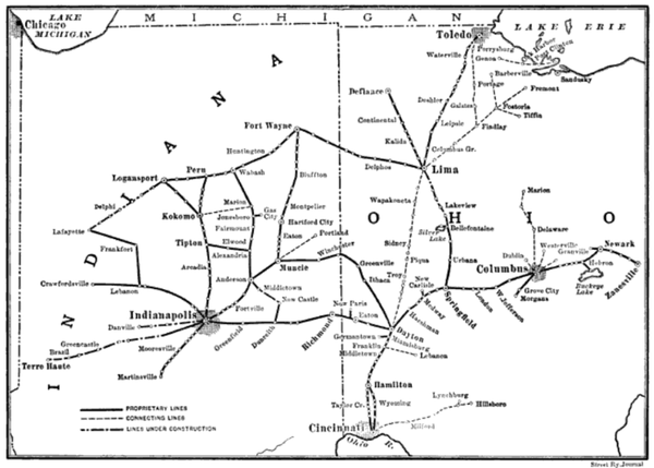
The Schoepf-McGowan Syndicate now controls a large majority of the electric railway mileage in Central and Western Ohio and practically all of the roads of Central Indiana centering in Indianapolis. These roads include the following properties:
Cincinnati & Northern Traction Company; Indiana, Columbus & Eastern Traction Company; Lima & Toledo Traction Company; Dayton & Muncie Traction Company; Richmond Street & Interurban Railway Company; Indianapolis & Eastern; Indianapolis & Western; Indianapolis & Northwestern; Indianapolis Coal Traction Company; Indianapolis & Martinsville Rapid Transit Company; Indianapolis Traction & Terminal Company; Indiana Union Traction Company; La Fayette-Logansport Line.
The Indiana, Columbus & Eastern is a consolidation of the Dayton & Western; Dayton & Northern; Dayton, Springfield & Urbana; Urbana, Bellefontaine & Northern; Columbus, London & Springfield; Grove City & Southwestern; Central Market; Columbus. Buckeye Lake & Newark; Columbus, Newark & Zanesville; Zanesville Railway & Light Company, and Columbus & Lake Michigan Railway.
The Lima & Toledo Traction Company includes the Fort Wayne, Van Wert & Lima, the Lima Railway & Light Company and the new line between Lima and Toledo.
The syndicate's system, consisting, as it does, of the consolidation of a very large number of small properties built under independent auspices, contains a wide variety of small power stations which, naturally, lack uniformity, and the syndicate is now actively engaged in standardizing the power equipment of the whole system, which, when completed, will present a uniform scheme of power transmission at 33,000 volts pressure. The accompanying map shows the lines owned by this syndicate, as well as the new lines under construction. The present plans of reorganization include the building of new stations at Fort Wayne and at Lindenwald, a suburb of Hamilton, Ohio, the addition of new machinery at Zanesville, Hebron, Medway, Indianapolis and Lima, and the abandonment of about a dozen smaller direct-current stations, which will be either entirely dismantled or re-equipped for sub-stations. As far as possible, the standards to be adopted in all the new work and additions to the old stations which have been retained include the use of 1500-kw Westinghouse turbo-generator units and 33,000-volt transmission lines. The standard car equipment will consist of four 75-hp Westinghouse motors per car, operated by the unit switch system of multiple control.
THE FORT WAYNE POWER STATION
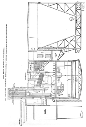
The most important work of reconstruction includes the new power stations at Fort Wayne and Hamilton, both of these stations, in conformity with the plans for standardization, being al most identical. The accompanying illustrations show a cross-section of the Fort Wayne power house and coal-handling apparatus, from which the general design of the plant may be readily seen. The chief feature of the design is the placing of the turbine room above the boiler room.
The main building is a two-story structure, the foundation being of concrete and the superstructure of red pressed brick. The lower floor is used as a boiler room and the second floor for the steam turbines and generators. The equipment of the generator room includes two 1500-kw, 25-cycle Westinghouse turbo-generators; one 400-kw, 25-cycle Westinghouse turbo-generator; six 375-kw, oil-insulated, self-cooling transformers, and three 500-kw, 25-cycle rotaries. In addition to the above-mentioned equipment, which is for interurban railway purposes, the station will also contain two 500-kw, 60-cycle, 2300-volt Westinghouse turbo-generator units, one 500-kw, 60-cycle turbo-generator for lighting purposes, and one 300-kw, 60-cycle rotary transformer for power purposes. The location of these units is indicated on the plan of the engine room shown herewith. It will be seen that the capacity of the station can be indefinitely increased by extending the length of the building and adding as many similar units as may be required.
The boiler equipment consists of ten 400-hp Babcock & Wilcox boilers, which will carry 175 lbs. pressure, and contain superheaters for superheating the steam to 75 degrees. The boilers are equipped with Roney stokers, and the ashes are delivered to a pit beneath the furnaces and underneath the boiler room floor. These ash pits communicate by means of doors with a passage under the boiler room floor running the full length of the building, and a track will be provided in this passage-way for cars into which the ashes from the pits can be emptied and carried away. The boilers are fed by two Yough pumps built by the Boyts-Porter Company, of Connellsville, Pa. These have 20-in. and 12-in. cylinders by 30-in. stroke. These pumps are located in the passage-way back of the boiler room, which runs the full length of the building.
Each of the 1500-kw turbine units exhausts into a pair of 24-in. Bulkley twin condensers. The 500-kw turbine is connected to an 18-in. condenser and the 400-kw turbine to a 16-in. condenser of the same make. The circulating pumps for all of the turbine units are of the same make as the boiler feed pumps. Those for the large units are 20 ins. and 36 ins. by 48 ins., and those for the small turbines are 12 ins. and 20 ins. by 48 ins. All of the station auxiliaries exhaust into two Platt Iron Works' heaters of 3000-hp capacity each. There are also two tank pumps of 12 ins. and 12 ins. by 18-in. stroke for pumping water from a hot-well to an overhead tank for the house supply. This tank is of 25,000 gallons capacity, and was built by the Chicago Bridge & Iron Works. The Custodis chimney is located in the rear of the building near the center, and is 12 ft. inside diameter by 185 ft. in height.
The generator, rotary converter and exciter switchboards are arranged parallel to one side of the station in front of the generating units on the second floor. The generator room is faced with white enameled brick, and contains a 20-ton traveling crane built by the Niles Tool Works. The generating sets are provided with casings from which a supply of cool air from outdoors circulates. This air is taken in through a duct extending the full length of the building underneath the floor of the generator room, and the air, after circulating around the generator units, is discharged into the boiler room. It was found that the amount of air required for cooling purposes corresponded almost exactly to the amount necessary for the boilers, so that, by dis-charging it into the boiler room, it was easily and conveniently disposed of.
The water supply for this station is taken from a river near which the station is located by means of a concrete intake pas sage extending the full length of the building, and a branch from this running out at right angles to the river. A crib was built at the intake end of this passage and water from the river lows into the lowest level of the passage. The hot water is discharged at a higher level in the same passage-way, on the down-stream side of the crib, at some distance from the point of intake, so as to avoid any return of the hot water for condensing purposes.
One of the most interesting features of this plant is the coal-handling device, which is shown in cross-section in one of the accompanying illustrations. A large concrete pit for coal storage is built at one side of the station, extending the whole length of the building. This pit has a capacity for storing 7500 tons of coal, and is entirely open overhead. It is surmounted by a traveling gantry crane built by the Fairbanks, Morse Company, which has a track gage of 60 ft. The crane carries a 1-ton Kester bucket, into which the coal is raised from the pit and deposited in a single-roll McCaslin coal crusher on the side of the crane next to the power house. The gantry crane has a travel of 180 ft., which is the full length of the building, and the coal, after passing through the crusher, is delivered into a bunker extending the full length of the building and 'having a capacity of about 400 tons of coal. From this bunker chutes pass down in front of each boiler and feed the coal into the stokers.
The coal is delivered to the pit from a railroad siding, the cars passing directly overhead on the tracks. By means of this arrangement no overhead coal storage is required in the station building, which greatly reduces the cost of coal storage equipment. Furthermore, the fire risk to the station is greatly reduced by having all the coal stored in the open air, where, in case of fire, no damage to the building would result.
The step-up transformers are located in vaults at one side of the generator room, and all of the high-tension wiring is to be run in ducts.
LINDENWALD POWER STATION
The other new station is located at Lindenwald, near Hamilton, Ohio, and is so generally a duplicate of the Fort Wayne plant that the buildings were erected after the same drawings. Almost exactly the same arrangement of machinery will be found in the latter station, except that there are no lighting units at Lindenwald.
This station contains three 1500-kw and one 750-kw Westinghouse turbo-generator units, and eight 400-hp Babcock & Wilcox boilers with superheaters. The same type of auxiliaries is used here as at Fort Wayne, and, as their location and arrangement is exactly the same, a detailed description is unnecessary.
ADDITIONS TO OLD PLANTS
The present plant at Medway, Ohio, has been enlarged by the removal of one 325-kw, direct-current generator and the addition of one 1500 and one 750-kw Westinghouse turbo-generators. The current from these machines is stepped-up to 33,000 volts by three 70-kw Westinghouse oil-insulated, self-cooling transformers. The section of the road adjacent to the station is supplied by means of one 300-kw Westinghouse rotary converter and three 110-kw transformers, which have also been recently installed.
The boiler room of this plant has been extended 39 ft., and two 525-hp Babcock & Wilcox boilers with superheaters are to be added. A new red brick stack is now in course of erection, which will be 9 ft. in diameter at the bottom, 8 ft. at the top, and 150 ft. high. Wheeler surface condensers and centrifugal pumps are being installed for the new units, which make the total electric capacity of the station 4500 kw.
 |
 |
At the Indianapolis station there are being added two 1500-kw. Westinghouse turbo-generator units and four 500-kw Westinghouse oil-insulated, self-cooling transformers, one of which is held in reserve. The turbo-generators deliver current at 390 volts, which is stepped-up to 33,000 volts for the overhead distribution. One 1 5 00-kw rotary is also being installed to feed about six miles of the interurban line now building west of Indianapolis. The boiler room is being enlarged by the addition of 2400-hp Babcock & Wilcox boilers with superheaters, the boilers being in 400-hp units. Baragawanth condensers are being installed for the new units, and the condensing water will be supplied by Boyts-Porter pumps. All of the boilers are provided with Roney stokers, and the new units have settings faced with white enameled brick.
As the water in this station is bad, especially at certain seasons of the year, a water-purifying plant has recently been installed, which is giving excellent results. This plant was built by the United States Wind & Engine Company, of Batavia, Ill., and consists of three tanks, each having a capacity of 77,000 gallons. Water from the river is pumped into these tanks and is thoroughly aerated by means of compressed air, and to each tankful of water is added 110 lbs. of lime and 29 lbs. of soda ash. Each tank is alternately filled and allowed to settle, after which the water is found to be perfectly clear and soft.
In order to care for that part of the new interurban line between Lima and Toledo, which was recently opened as far as Leipsic, the power plant at Lima is being enlarged by the addition of one 375-kw, 550-volt Westinghouse direct-current generator, which is direct connected to a 530-hp Buckeye tandem engine.
The length of line just opened on this road is about 30 miles, and, as no high-tension alternating current is available at this point, a booster set has been added to the Lima station, to take care of the farther end of this line. The booster set consists of a 220-hp, 550-volt Westinghouse motor and a 1 5 0- kw, 250-volt, 600-ampere Westinghouse generator, which raises the feeder pressure to 800 volts. There are two 400-hp Babcock & Wilcox boilers to be added to this plant, which is designed to take care of the new extensions until final plans for the proper development of this section have been completed.
The capacity of the station at Hebron is being increased by the addition of more boilers, and at Zanesville a 500-kw Westinghouse motor-generator set and a 300-kw rotary transformer are being installed to provide for the extreme eastern end of the system.
It is the aim of the Schoepf-McGowan syndicate to standardize its lines and equipments throughout, as far as possible. The plant of the Indiana Union Traction Company, which contains five 1000-kw Westinghouse alternating-current generators, is the only one of the interurban power plants which is to be retained without some changes. This is an entirely modern and up-to-date equipment, and has already been thoroughly described in the technical press, so that further details at this time are unnecessary.
When the present additions and changes have been completed the company will have attained a remarkably uniform plan of power development and distribution, which will not only greatly simplify the operation of the system as a whole, but will largely decrease the amount of spare apparatus and repair parts which must always be carried in stock.
STORAGE BATTERIES
Many of the interurban roads in Ohio and Indiana are equipped with powerful storage batteries, used to improve the operation of the systems, as well as for reducing the operating costs. These storage batteries are usually installed with plates, merely sufficient to meet the demands of the load at the time that they are put in. The containing tanks, boosters and other accessories are, however, often considerably larger, so that as the load grows the battery may be increased in size by the addition of plates; and, as to giving an idea of the great extent to which batteries are used in this class of work, it will be interesting to know that at the present time there are over 25 installations in the State of Ohio and 16 or more in Indiana, making a total of over 40 for the two States on interurban work alone. These have been furnished by the Electric Storage Battery Company, of Philadelphia. These aggregate an initial capacity of 9376 kw at the 1-hour rate of the battery and 11,710 kw-hours when the batteries have been increased to their ultimate capacity.
The Northern Ohio Traction & Light Company has a battery with an initial capacity of 192 kw and an ultimate capacity of 288 kw operating at its Bedford station. Before this battery was installed it was necessary to operate two 250-kw generators to carry the load at all times. Since the battery was installed the road has operated a large portion of the time with but one generator, which has resulted in a large saving of coal. Another battery, with a capacity of 140 kw, is operated on the Ravenna division as a line battery. This installation has resulted in maintaining a minimum voltage of 400 volts on this line, whereas previously it fluctuated between 100 and 500 volts.
The Cincinnati Northern Traction Company has a battery of 120 kw in glass jars installed at its Dwyer sub-station. This battery, by removing the fluctuations due to starting and stopping of cars, climbing grades, etc., enables the station to be operated a very large portion of the time with one rotary.
The Dayton & Northern Traction Company was the pioneer of Ohio in the use of storage batteries for interurban work. It was the first to equip its road in this manner, and the installations at Brookville and Arcanum each consists of a 260-kw battery operating in sub-stations. This road was especially designed with a view to the use of batteries, and it was, therefore, enabled to install smaller generators and rotaries than had the batteries been omitted.
VOLTAGES
In the table showing the voltages used on interurban systems in the States visited, it will be seen that there is considerable difference in the figures, and that the reason for these differences is not obvious. There has been a steady increase in the voltage of three-phase transmission lines, and even at the present time there appears to be nothing to check this increase.
Sixty-six hundred volts was at one time considered to be about the limit for this work, and a little later this figure was doubled, giving the well-known figure of 13,200 volts. In the mean-time, one or two systems had started operation at 11,000 volts. Soon after some installations began operating at 13,200 volts a few roads were projected, which, on account of their length, required transmission voltage higher than this figure, and it was again doubled, making the figure 26,400 volts. In the meantime, other plants found it advisable to double the figure 11,000, giving some plants operating at 22,000 volts, and in cases where this was insufficient 33,000 volts had been used; and there were also a few plants where 11,000 volts appeared to be insufficient, and where 22,000 was higher than seemed necessary. These plants split the difference and adopted the voltage 16,500. It will be noticed that all of these figures are multiples of 110, the well-known figure for incandescent lamps.
It will also be found that many of the railway plants have voltages which do not fall exactly on these figures, but come more or less closely to one of thesee. g., the 26,400 may be either as low as 25,000 or as high as 27,000, and there are many intermediate figures between 10,000 and 13,200.
These latter variations in voltages are partly due to the various interpretations which are placed on the standardization recommendations of the American Institute of Electrical Engineers, which read as follows: "In alternating-current, high-pressure circuits, at the receiving end the following pressures are in general use, and are recommended: 1000 volts, 2000 volts, 3000 volts, 6000 volts, 10,000 volts, 15,000 volts, 20,000 volts." As these figures were stated as being the voltage at the receiving end, the voltage at the generator, or step-up transformers, was a variable quantity, such as 5, 10 or 15 per cent greater, depending on the slide rule calculations and assumptions of the engineer in charge of the transmission. Consequently, one man winds his generator for 10,000 volts, while others wind for 10,500, 11,000, 11,500 or 12,000, or intermediate figures, and all of these people believe they are following the Institute standard.
It is also a matter of pride with operating engineers to have the voltage of their system higher than their neighbors, so that they will always mention the voltage of the generator or step-up transformers rather than the voltage at the receiving end. Also, the number of plants which generate at one point and have their load concentrated at a single point are extremely few, so that the receiving voltage must be graded all the way from the generating station to the most distant point, where the line drop is greatest.
With few exceptions, 25 cycles is the standard frequency for railway rotary converter work, and a tabulation of the plants operating at this frequency will show that there are more operating at 13,200 volts than at any other figure. The usual practice in railway work, not only at this voltage, but at the higher voltage, is to wind all the transformers at the full line potential, adding taps (usually four) giving 10 per cent range in 2-1/2 per cent steps. This arrangement makes the transformers interchangeable, and permits of adjustment to compensate for as much as 10 per cent line drop, this figure being rarely exceeded in railway transmissions, and, in fact, cannot be greatly exceeded without the chance of starting pulsation of converters. The taps also have the additional advantage of compensating for differences in ratios of transformers and converters of the same or different manufacture.
It is obviously desirable to have in general use as few different voltages as will meet the various requirements, as this should not only mean better prices and deliveries on main apparatus, but also on auxiliary apparatus, such as switches, current and potential transformers, insulators, lightning arresters, cables, etc.
|
|
|
|
At the present time there is a general tendency to make use of 33,000 volts on systems where 13,200 volts is not enough. If these transformers are made Y connected for 33,000 volts they may be connected delta at approximately 19,100 volts, in case the length of transmission or the load are such as to make operation at the higher figure unnecessary. Two lines of transformers, therefore, namely, 13,200 volts and 33,000 volts, Y connected, would appear to be sufficient to meet most of the railroad requirements at the present time, and the proposed use of any other voltage on 25-cycle railway work should be questioned. The cases where other voltages are justified are cases where nearby systems are already in operation at other figures. In these cases the inevitable extensions and consolidations will, sooner or later, make it desirable to operate the two systems either from one large power house or interchange power for greater flexibility and reliability in operation, e. g., as has been done in large city works. For instance, Chicago has an extensive system in operation at 9000 volts. Buffalo and New York City have railway systems operating at 11,000 volts, while most of the other large cities -- San Francisco, St. Louis, Minneapolis and St. Paul, Baltimore, Philadelphia and othersoperate at 13,200 volts.
In the State of Ohio there are a number of roads operating at 26,400 volts, and others at 33,000 volts. The latter and higher figure is in better standing and of more general use, but there may be locations where the possible purchase or interchange of power would justify standing by the lower figure.
The transformer is a very flexible piece of apparatus, and while this has advantages it also has disadvantagese. g., a man having transformers wound for 33,000 volts may decide that this voltage is too high for his needs and decides to operate at 16,500 volts by parallel connection of primary coils. Another man under the same conditions, instead of parallel connection, may change from Y to delta connection and operate with this same apparatus at, roughly, 19,000 volts. Another engineer, finding that his road has outgrown the original 13,200-volt transmission, will change his transformer from delta to Y and operate at approximately 22,800 volts. This flexibility of connections, while at times convenient, is obviously the direct means of introducing a large number of new "standard" voltages. It is apparent, therefore, that any recommended figures for standard transmission voltages which do not take into account the same transformer connected both Y and delta, will have little following. This ratio is 1.73 in the case of changing from delta to Y, or 0.58 in the case of changing from Y to delta. A consistent line of transformers, therefore, would take these ratios into accounte. g., 11.000 volts, 19,100 volts, 33,000 volts, 37,000 volts, 100,000 volts. Each of these figures is 1.73 times the next lower and 58 per cent of the next higher. The figure 100,000 is forecasting the future a little; but, approximately, the figure 57,000 is already in considerable use. Even if these figures were taken as standard, and transformers built only to meet these voltages, there would be nothing to prevent the purchaser from halving any of these figures by connecting coils in parallel, and again connecting the paralleled coils in Y, which would immediately make a lot more of "standard" voltages.
 |
On 13,200-volt plants it is common practice to generate directly at this figure, thus dispensing with the use of step-up transformers. This is by no means the possible limit of direct generation, as one road in Ohio generates directly at 16,500 volts; but 13,200 is the highest figure for direct generation in common use. Where the voltage must be higher than this. such as 33,000 volts, the generators are usually wound for 2200 volts, unless there happen to be rotary converters in the same building with the generators, in which case three-phase generators, operating at approximately 370 volts, give the desired direct-current voltage of 600.
 |
Twenty-two hundred volts is selected on account of the moderate size cables required, and also because switches and other accessory apparatus are developed and in general use at this figure. Twenty-two hundred, like the other figures, is also a multiple of 11, and, therefore, the high-tension voltages of 13,200, 33,000, etc., are multiples of the low-tension voltage.
Three hundred and seventy volts, while quite satisfactory for the smaller generators, requires very cumbersome connections, cables, switches, bus-bars, etc., as soon as the generator gets to be as large as 1000 or 2000 kw. On account of the simplified switching equipment, many roads regard generator and bank of transformers as single unit, making low tension connections permanently between the two, and thus dispensing with large low-tension bus-bars and switches. In fact, this simplification and saving is so great that some roads are found with converters in the same room, making use of both step-up and step-down transformers to feed these converters. While this means increased losses and increased transformer expense, the simplified switching is considered to justify the arrangement.
A few years ago more or less publicity was given to a convenient rule for determining transmission voltages. This was to take 1000 volts for every mile of transmission. This rule is very easily applied, and, while not far from general practice, it doubtless was responsible for much of the special apparatus and unusual voltages.
The advantages of recognizing as small a number as possible of different voltages as standard for railway work are so obvious as to require no further comment.
SUB-STATIONS
Opinions differ considerably among engineers and operators as to the most desirable sizes of sub-station equipment and the distance between sub-stations. Some engineers figure that it is better to use a number of small stations and place them at frequent intervals, claiming that the voltage is better maintained and that the loss of one or two sub-stations on a line affects the service less than where the stations are further apart and the size of rotary converters larger. The Toledo & Western has an average distance between stations of 8-1/2 miles, and the capacity of each station is either 250 or 300 kw. The company makes a practice of cutting out one or two of its intermediate sub-stations during hours of lightest travel. The Lake Shore Electric has an average distance between sub-stations of 10 miles and on one end of its system these stations are equipped with two 200-kw rotaries, while on the other end there are one or two 400-kw rotaries. The company advocates the use of the larger machines as they provide a greater reserve, being capable of greater overloads during periods of peak loads. The company is planning to place larger rotaries in several of the stations now equipped with 200-kw units, and it will probably transfer some of the smaller machines to other stations, giving some of the stations a large and a small machine; the larger machine to be used during normal condition and the smaller one to help on peak loads or to handle the load alone on very light load. The Western Ohio, with sub-stations averaging 12 miles apart, also has two 200-kw machines in the majority of its stations. While its power conditions are excellent, the company rather advocates the use of larger machines. The Toledo & Indiana, with an average distance of 12 miles, takes an intermediate position, and uses 360-kw rotaries. The Cincinnati, Milford & Loveland, Cincinnati & Columbus and Interurban Railway & Terminal Company each use 400-kw rotaries with but one in the sub-station. The Toledo, Port Clinton & Lakeside and the Scioto Valley using Bullock apparatus were extremely liberal in the equipment of their sub-stations, which average 10 miles apart and are equipped with 450-kw rotaries.
 |
The working voltage through which current is reduced in substations also varies considerably. Two roads, the Stark Electric and the Cincinnati, Georgetown & Portsmouth, both using Westinghouse apparatus have a secondary voltage for the transformers of 350. The Toledo, Port Clinton & Lakeside and the Scioto Valley with Bullock apparatus reduce it to 375 volts. The Western Ohio, with Westinghouse apparatus, reduces to 420, and the Fort Wayne, Van Wert & Lima, with General Electric transformers, to 440 volts. The sub-stations on the Canton-Akron, Cincinnati & Columbus, Toledo Urban & Interurban and the Medway and Hebron stations of the Indiana, Columbus & Eastern, equipped by the General Electric Company, have transformers cooled by air supplied by motor-driven fans. In the majority of the General Electric Company's latest installations in this district, oil-cooled transformers have been used. The Toledo & Indiana has one station equipped with oil-cooled transformers, built by the Kuhlman Electric Company, of Elkhart, Ind. These transformers are unusually large for the capacity and have plain cases. Below each transformer is a tank, into which the oil can be drained in case of fire or other emergencies.
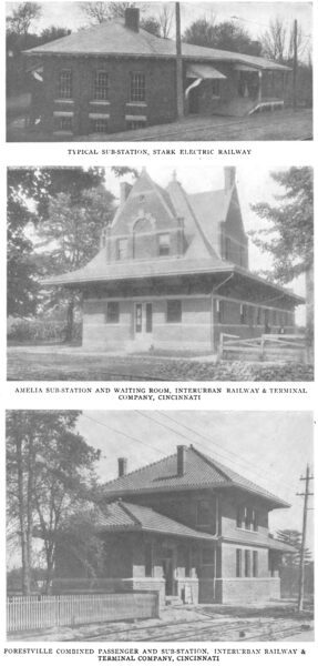
With reference to the best sites for substations in general, there are two distinct ideas on this subject. One is to place substations in villages and have the attendant perform the varied duties of station attendant, ticket agent and freight agent. This necessitates the designing of buildings to accommodate all of these requisites, and it might be said that this practice has been largely followed. Lately, however, there has been an inclination on the part of some roads to isolate their sub-stations by placing them in the country and allowing the attendant to give his exclusive attention to the sub-station apparatus. The theory is that when something goes wrong, the man should be on the spot to remedy the difficulty as quickly as possible, and it is claimed that he cannot always do this if he is out selling tickets or checking baggage. The growing tendency in small towns to object against the passing of high-tension lines through their streets also has a bearing on this point. The Scioto Valley believes in isolating its sub-stations and machinery, and although in a number of places its stations are in towns, the ticket office and freight station are in another building and have a separate attendant. The Western Ohio has several isolated sub-stations and for these it has built very attractive two-story brick residences, fitted with all the conveniences of a modern home, and the attendant lives there and is on duty practically all the time. The Toledo & Western has several combined residences and stations, but they are all in towns and the agent divides his duties.
In Indiana the average distance between sub-stations on the roads visited varies from 21 to 12 miles. The greatest distance was found on the Indianapolis, Columbus & Southern, where there is but one substation in addition to one in the power house. A distance of about 15 miles is the average for all of the roads visited.
On the Indianapolis Northern division of the Indiana Union Traction Company, sub-stations are, with one exception, 17 miles apart. This is a somewhat greater distance than on the older portion of the system, as on this the stations are from 7 to 11-1/2 miles apart.
Usually the locations of sub-stations are not the most economical ones so far as the line losses are concerned. In most every instance they are located in small towns along the line with a view, in some cases, to combining the sub-station attendant's duties with others. The sub-stations of the Indianapolis & Northwestern system, however, are located 16 miles apart irrespective of towns.
The step-down transformers in the substation range in size from 300 kw to 150 kw. With few exceptions they are of the oil-cooled type. Those of the Indianapolis & Northwestern system are air cooled. These transformers, moreover, are peculiar in that they have two separate secondary circuits so that two rotary converters can be supplied from one set of transformers. Rotary converters range in size from 350 kw on the Indianapolis, Columbus & Southern system to 200 kw.
The earliest sub-stations were designed with the high-tension switches, lightning arresters and transformers in a room separate from that in which the switchboard and rotaries were installed. However, there is a decided tendency to abandon this practice. Practically all of the stations erected in the last few years have all of the apparatus in one room. In many instances the high-tension apparatus has no railing, screen or protection of any kind. around it. The new stations of the Fort Wayne & Wabash Valley Traction Company have protecting screen about the high-tension switches and transformers. On the Rapid Railway division of the Detroit United Railway the high-tension apparatus is separated from the balance of the room by a railing and in some instances it is on an elevated platform. The sub-stations of the Detroit, Ypsilanti, Ann Arbor & Jackson Railway are provided with an entrance tower and in this and immediately underneath it all of the high-tension apparatus is installed so that it is partially isolated.
There is no generally adopted method of bringing the high-tension wires into the sub-station. On the Terre Haute Traction & Light system the wires are brought in through the center of 12-in. drain tiles. The inner end of each tile is provided with a disc of plate glass and the wire is carried through a 3-in. hole in the center of this. The high-tension wires are brought into sub-stations through porcelain tubes on the Indianapolis, Columbus & Southern system.
The sub-stations of the Indianapolis & Northwestern Traction Company were the only ones found in which motor-operated oil-break high-tension switches are employed. The Westinghouse "stick" type combination fuse and switch is used by the Indiana Union Traction Company, the Fort Wayne & Wabash Valley Traction Company and by several other of the systems visited. The Indianapolis, Columbus & Southern Company employ Stanley hand-operated oil switches. In the sub-stations of the Indianapolis & Cincinnati system no automatic switches are provided. This road is operated by single-phase current and the sub-stations are merely transformer stations. As no attendant is required, the breakers are placed in the power house only.
On the Indiana Union Traction system, as originally laid out, fourteen sub-stations are fed from six circuits. Additional sub stations of roads operated by this company will be fed from these circuits within a short time. Two circuits are usually run to those sub-stations nearest the power house. Two sub-stations of the Indianapolis & Northwestern system are fed from one circuit. The longest transmission at high voltage in Indiana and one of the longest in existence where the current is not generated by water power is that of the Indiana Union Traction Company between Anderson and Logansport, a distance of about 60 miles, and from Anderson to Hill Top, about 61 miles. For the greater portion of the distance to Logansport two No. 6 transmission lines are employed. The Fort Wayne & Wabash Valley Traction Company will transmit 50 miles when present plans are put into operation. On the Detroit, Ypsilanti, Ann Arbor & Jackson Railway system current is transmitted 41 miles, and on the Indianapolis & Cincinnati Traction system current is carried from the power house at Rushville to the city limits of Indianapolis, about 40 miles distant.
The power distribution system of the Indiana Union Traction Company is the most extensive one in the Middle West. For the past two years fifteen sub-stations have been fed from the one generator station at Anderson. Within a few months seven sub-stations will be fed from the Rushville power house of the Indiana & Cincinnati Traction Company and the distribution system planned for the Fort Wayne & Wabash Valley Traction Company will include seven sub-stations.
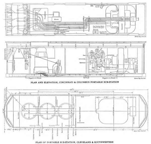
FLOATING OR PORTABLE SUB-STATIONS
Portable sub-stations are used extensively on the longer roads in Ohio. The uses to which they are put, however, are not identical in every case. Several roads which had rather indefinite plans for extensions when the original installations were made adopted the idea of placing the sub-stations in cars, so that they might be moved if later extensions were made and a change in the distribution system found desirable. Thus, the Toledo & Western, the Toledo & Indiana and the Cleveland, Painesville & Ashtabula each had two or three portable substations. These were laid up on convenient sidings and served the purpose of permanent sub-stations. This practice has since undergone some change on these roads. The Toledo & Indiana had one of its cars struck by lightning, the oil transformers exploding and completely destroying the car and its equipment. The difficulty of placing suitable protecting apparatus in so limited a space necessarily constructed of wood caused the company to abandon the idea of using it for a permanent station, and a concrete building was substituted. The Toledo & Western uses one of its portable sub-stations practically all of the time, while the other is side-tracked for use in cases of emergency. It is believed that this later use is the true function of the floating sub-station.
In addition to the roads mentioned, the Cleveland & Southwestern, Cincinnati & Columbus, Toledo, Port Clinton & Lakeside and the Dayton & Muncie have floating stations used in this way. On occasions of heavy loads on certain parts of the road, such as fairs or base-ball games, or on longer periods of exceptional traffic, these cars are placed on the most advantageous side track and assist the regular sub-station in that district in carrying the load. An illustration on another page shows a portable sub-station placed on a side track adjoining one of the permanent stations, the two operating in parallel and providing double the output ordinarily needed for that section of the road. In cases of accident to one of the permanent sub-stations the portable apparatus is quickly shifted to that locality and the service is maintained without interruption. The longer roads which own such stations as a rule believe that the added investment for the sub-station equipment is well spent, as it provides an assurance against interruption of traffic which could not otherwise be obtained. In several instances the floating stations are simply old freight cars strong enough to carry the weight, while in others special cars were designed. The floating sub-station designed for the Cincinnati & Columbus Traction Company shows unusual attention to details in that it is equipped with complete systems of oil switches and high-tension lightning arresters, which some of the earlier cars did not have. This outfit was described in the STREET RAILWAY JOURNAL for July 8, 1905. It contains a 440-kw rotary in one end, larger than is found in other floating sub-stations, and at the other end is one to -phase transformer, this outfit being lighter and smaller than where three single-phase transformers are used. In the rear of the transformer are the lightning arresters and lever operated oil switches, potential and current transformers, etc. The high-tension lines enter through an anchorage at the same end of the car, so that no high-tension apparatus passes in front of the transformer, insuring safety to the sub-station attendant. The transformer is of the air blast type, and the current of air passes through a chamber below the car floor, in which are also the low voltage and direct-current wiring. The Columbus, Newark & Zanesville was recently called upon on short notice to handle an unusually large excursion at Buckeye Lake, and the manager, in solving the power problem, arose to the occasion by dismantling one of the permanent sub-stations, loading the sub-station apparatus on a flat car and placing this improvised portable sub-station on a siding near the lake, where it distributed direct current to the line as required.
With the exception of the Indiana Union Traction Company and the Fort Wayne & Wabash Valley Traction Company, none of the systems visited in Indiana employ sub-station cars to serve as reserve capacity. The Rapid Railway Division of the Detroit United Railways has ample reserve capacity in each sub-station in permanently installed apparatus, as do several other of the systems.
The Indiana Union Traction Company has two portable sub-stations. One of these is contained in a box car, 21 ft. 6 ins. long and 8 ft. 8 ins. wide, and consists of three 87-1/2-kw, oil-cooled, step-down transformers and a 250-kw rotary converter. The transformers are located in one end of the car, the converter in the opposite end, while the switchboard occupies the space in the center. The second portable sub-station is mounted in a car somewhat longer, but containing practically the same apparatus as the first one. The roof of the second car is arranged so that it can be lifted off in two sections. This is to facilitate changing the transformers should it be necessary. In such an event it is intended that the car shall be run under the crane in the power house so that the roof and the apparatus can be handled by the crane. This portable sub-station of the Fort Wayne & Wabash Valley Traction Company consists of a 200-kw rotary converter and three oil-cooled transformers mounted in a car of practically the same dimensions as are the sub-station cars of the Indiana Union Traction Company. The cars on both systems are used when, for any reason, traffic on any portion is exceedingly heavy. They are also used whenever it is necessary to repair the regular sub-station apparatus.
LINES AND CABLES
Practically every road in Ohio carries its high-tension lines on the poles supporting the trolley wires and direct-current feeders. In other words, there are few separate transmission lines except in several instances cross-country lines have been built to provide short cuts from power stations to sub-stations. In the case of the Toledo Urban & Interurban, which was equipped with high-tension transmission several years after its original road was built, on some sections separate poles have been erected for the high tension. Poles are uniformly 35 ft. or 40 ft., except in a number of instances where poles of 50 ft. and 60 ft. were employed to carry the high-tension wires over the tops of trees. Roads following highways and passing through villages in Ohio have been greatly troubled by the presence of trees, which, as a rule, owners were unwilling to have trimmed. There are a number of instances where pole lines were carried to the rear of lots in order to avoid trees, and nearly every road has one or two places in which it was obliged to carry its transmission lines to the rear of towns in order to avoid the trees and accommodate the ideas of village authorities.
 |
Methods of arranging and attaching high-tension wires to poles have furnished another subject for wide discussion among engineers, but it may be stated that notions which were prevalent a few years ago are now being dispelled and the various roads are coming nearer to a standard on their transmission lines. This, of course, is largely the result of combinations of interest and the necessity for putting various lines together.
For example, one prominent engineer provided in his specifications that there should be no iron of any kind at the tops of the poles, all pins, bolts and braces being of hardwood. In later construction on this same road this idea has been modified, as it was found that such precautions were unnecessary, and that the line was not as strong as where metal was used more freely. Up to two or three years ago the majority of engineers held firmly to the belief that three-phase transmission lines should be arranged in an equilateral triangle and that they should be transposed at regular intervals. The majority of Ohio operating men now believe that these two ideas were the result of too much theory and not enough practice. The latest transmission lines are attached to cross-arms, according to the arrangement which is most convenient, and there is no transposition of wires. While the triangular arrangement is still used, it is largely the result of the desirability of using two sets of transmission lines, and two cross-arms are employed, one, shorter than the other, carrying two insulators on its ends, and the other carrying four insulators. On some of the roads the longer arm is placed above, while in others the opposite arrangement is followed.
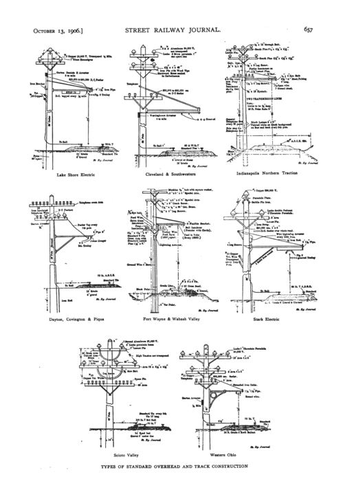 |
On the matter of spacing circuits, however, one point is becoming impressed on roads using the higher voltages, and that is that there should be ample space between the wires to avoid short circuits and jumping across in case of overloads. The Western Ohio, for example, formerly had 32 ins. between wires for 33,000 volts transmission. It is now spreading these, and, at the same time, strengthening its construction, using 10-ft. arms for four pins and 8-ft. arms for two pins and providing for a minimum distance between wires of 36 ins. Pins are 15 ins. long instead of 10 ins., as formerly used. The Fort Wayne, Van Wert & Lima and the Toledo & Lima follow this practice quite closely in their new work. The Cleveland Construction Company, which is building several new lines, is providing for a spacing of 42 ins. between wires, and it uses 16-in. pins boiled in carbo-lineum. It might be stated here that wood pins are almost universally used.
The idea of placing one pin on the top of the pole and the other two on a cross-arm below it where but a single transmission line is provided for, is losing favor among some of the best engineers. The pin and insulator on the top of the pole almost invariably gives more trouble than the other two. There are, of course, several methods of attaching this pin. The Toledo, Port Clinton & Lakeside uses a metal ridge pin with four heavy lag screws, which is undoubtedly a strong form of construction. On the Cincinnati, Milford & Loveland and several other roads a wood block is attached to the side of the pole and the pin is batted to this. On a number of roads the top of the pole is drilled and the pin set in. The objection found to this is that moisture gathers in the hole and the pole rots in the center. On several roads this has been partially overcome by boring "weep" holes for the moisture to drain out and by placing porcelain plates around the top of the pole, but after trying these various devices there are a number of prominent engineers who believe it is best to get the insulator off from the top of the pole and place all these wires on a single cross-arm. This has been done on recent construction work on the Western Ohio and the Toledo & Indiana, using one insulator on one side of the pole and two on the other. The Cleveland & Southwestern on some recent work used two short cross-arms with an insulator on the end of each, the fourth insulator being for a spare wire which is used in case of breakage to any of the other three. Tell-tale devices in the sub-stations tell which wires are dead, and the spare wire can be thrown instantly into service in case of accident. This device has saved a tie-up on several occasions. A variation from usual forms of cross-arm braces was used in this work, a triangular shaped block of wood soaked in carbo-lineum to prevent cracking, being used instead of metal braces, which had given trouble.
Copper lines are used by the great majority of roads, although considerable aluminum has been used during the past two or three years. During the past twelve months, however, builders of roads have been unable to secure proposals from manufacturers of aluminum wire because they are too busy with other work, hence it is not being used on roads under construction. One of the chief advantages found for aluminum is that sleet does not stick to it, in spite of the larger area of surface, and aluminum lines have gone through the most severe sleet storms without interruption, where copper lines have broken down in many places. The lower fusing point of aluminum, as compared with copper, and its liability to break when coming in contact with electric light or telephone wires, are, of course, disadvantages which perhaps more than compensate for the advantage mentioned. At times when copper has been high in price aluminum has been considerably lower for the same carrying capacity, and, as a rule, it is always a trifle lower in price, the price being based upon the price of copper. On long spans, aluminum has been known to stretch considerably when first erected, but one of the advantages frequently pointed out for aluminum is that the manufacturers have always insisted upon inspecting all erection work, requiring that the feeders be strung at the proper tension and in the most substantial manner possible.
The Scioto Valley Traction Company uses seven-strand aluminum of No. 2 capacity for its lines, and has had excellent results. The Western Ohio, Lake Shore Electric and Cleveland & Southwestern have secured very satisfactory results from aluminum.
Lines of No. 4 capacity are used by the majority of roads of medium length, while the roads with heavier equipment, longer transmission and higher voltages use a larger conductor.
The Canton-Akron Companys system is about equally divided between No. 2, No. 4 and No. 6, starting out of the house with the larger conductor and tapering down to the smaller at the ends. The Western Ohio uses No. 2 and No. 4, with the same arrangements. The Lake Shore Electric has all No. 2, in order to render it possible to run all the sub-stations from one power house if necessary, necessitating a transmission of about 100 miles. The Fort Wayne, Van Wert & Lima has No. 2 throughout, and there seems to be a tendency among other roads to adopt this on extensions and new lines, in order to secure ample capacity to handle the road from some other station in case the usual base of supply is interrupted.
Glass insulators are being used by several roads with the medium voltages of rom 12,000 to 16,500, but the roads using the higher voltages of from 20,000 to 33,000 seem to prefer porcelain insulators, the usual size being 7 ins. The Lake Shore Electric, with 16,500, uses 7-in. glass with most satisfactory results, while the Cleveland & Southwestern has a number of stretches of 8-in. glass insulators, which are giving excellent service. The Toledo Urban & Interurban and the Cincinnati & Columbus, with their 33,000-volt transmission lines, use 8-in. x 8-in. porcelain insulators designed for 90,000 volts, and the tendency is in this direction.
Considerable interest is being displayed in high-tension lightning arresters placed on poles, but as yet they have not been adopted by any of the roads in the district. The Detroit, Monroe & Toledo and Toledo Urban & Interurban string a galvanized iron barbed wire at the top of the pole and ground it at every tenth pole, which is said to be an excellent protection against lightning. Other engineers who have considered this scheme say that while it may be some protection, the comparatively short life of galvanized iron wire, as compared with copper wire, is likely to cause a great deal of trouble when the barbed wire commences to rust through and break, falling on the high-tension lines.
The majority of roads are now taking unusual precautions to protect their wires against telegraph wires at railroad crossings. In a number of places cradles have been erected below the transmission wires so that they cannot fall onto the telegraph wires. At one undergrade crossing, the Toledo & Western has insulated its high-tension lines and carries them under the crossing. The Dayton & Muncie in one place has erected 100-ft. lattice iron poles to carry the high tension over telegraph wires. At Lorain, crossing a navigable stream where vessels with tall masts frequently pass, the Lake Shore Electric has erected two 350-ft. towers and passes the wires over with a thousand-foot span, stranded aluminum wire being used.
In the other States visited copper is used for high-tension conductors in the majority of cases. Aluminum conductors are used by three systems, and in one instance the conductors are of phosphor-bronze. High-tension conductors vary in size from 1-0 copper equivalent to No. 5. The smallest size is used on the older portion of the Indiana Union Traction Company. On this system the two sub-stations between Anderson and Indianapolis are fed by one line, consisting of No. 5 copper conductors. Each of the sub-stations contain two 250-kw rotaries, and one is 13 miles and the other 24-1/2 miles distant from the power station. On practically all of the new work of this system the high-tension wires are of No. 3 copper. On all the systems visited, with the exception of the Indianapolis & Cincinnati Traction Company, the high-tension circuits are carried on the trolley poles. On this system, however, a second and separate pole line, placed on the opposite side of track from the trolley poles, is used. The majority of the systems use transmission poles 40 ft. long. The size, however, varies greatly, as poles with tops varying from 6 ins. to 10 ins. are used. On all of the systems visited the poles are placed 100 ft. apart.
Disposition of the high-tension wires in the form of a triangle was found in every instance, with the exception of the single circuits on the Indiana Union Traction system. The wires of these single circuits are all on one cross-arm, two being on one side of the pole. Wide differences were found in the distance between the separate wires of high-tension circuits. The distances range from 18 ins. to 40 ins., and, moreover, the greatest width was found on that system having the lowest transmission voltage. On the systems carrying the highest voltage distances of 35 ins. and 36 ins. between wires are usually employed.
The practice of transposing high-tension wires is adhered to by some companies and is not followed by others. Three systems were found having high-tension wires transposed. In two instances the transpositions are made every mile and in another they occur every 9000 ft.
Porcelain high-tension insulators are used on all but two systems visited. On one system on which glass insulators are used it was stated that no trouble whatever is being experienced with them except their occasional breakage by boys, but on another system glass insulators are being replaced by porcelain whenever breakage occurred. On the Rapid Railway division of the Detroit United Railways, and also on the Indianapolis & Cincinnati system, the high-tension insulators are carried on iron pins secured to the cross-arm by stud bolts. On all the other systems visited wood pins, usually locust, are used.
Several recent installations throughout the country have ground wires on the cross-arms carrying the high-tension wires as a protection against lightning. This practice was not found on any of the systems visited.
OVERHEAD CONSTRUCTION
Grooved, or Fig. 8, wire is used for trolley by the majority of Ohio roads. There is a growing tendency to equip with double trolley wire and reduce the size of the d. c. feeders. On the Toledo & Indiana, Cincinnati & Columbus and several other roads where the sub-stations are ample and fairly close together, the use of d. c. feeders was dispensed with, the trolley wires being used exclusively for carrying the direct current. The Canton-Akron Railway Company uses a special trolley wire, known as the Myers special, which is a modification of the Fig. 8, except that it is flat on top. It is believed that it gives the ear a better gripping surface, but, as it is unique, there is some difficulty in getting new ears and repair parts.
As with high-tension lines, aluminum has been used by a number of roads for d. c. feeders, and the same conditions apply as with the high-tension wires. The majority of the roads using a. c. transmission and having No. 000 single trolley use a 300,000 c. m. d. c. feeder. The Cleveland & Southwestern uses a 300,000 c. m. feeder where it has double trolley and 500,000 c. m. to 600,000 c. m. with much of its single trolley. A portion of this system has direct-current trans-mission, and on these sections it uses 60,000 c. m. The Dayton & Troy, with d. c. transmission, has No. 00 trolley and 1,000,000 c. m. feeders.
 |
 |
Practically all the work done in Ohio in the past two years has been bracket construction for single track. The older portions of the Lake Shore Electric, Eastern Ohio Traction, Cincinnati, Georgetown & Portsmouth and Toledo, Port Clinton & Lakeside are cross suspension, but later extensions were built with bracket construction, which has been found cheaper to build and to maintain. Span construction is used on practically all of the double track in the State, there being but very little center pole construction. The height of trolley above rail varies from 16 ft. on the Cincinnati & Columbus to 21 ft. on the Dayton & Troy, the usual practice being 18 ft. This is a point which ought to be adjusted, in view of the growing tendency to run cars over other lines. Soldered and clinch ears are about in equal favor, with possibly a growing sentiment in favor of the former. There is an increasing tendency to use longer and heavier ears, many 15-in. and 16-in. ears now being used.
Line voltages vary from 550 to 650, with a growing tendency toward the higher voltage. In figuring feeders, the usual rule is to allow for a maximum voltage drop of about 25 per cent, although several roads estimate copper upon a drop of only 100 volts.
Pole lightning arresters are used by all the roads. Arresters are placed from 1 to 6 to the mile, and it might be stated that there is a growing tendency to use more arresters and to see that they are maintained in order. Six out of seventeen roads visited ground the arresters to the rail exclusively, three ground to an iron rod driven into the ground, two ground to a copper plate and six use a combination of these methods, grounding both to rail and earth.
Bracket trolley construction is followed in practically all of the new work in Indiana and Michigan. Both round and Fig. 8 trolley is employed, but there is a tendency towards the abandonment of the Fig. 8 section. Three sizes of wire, No. 00, No. 000 and No. 0000 trolley, are used, the smaller sizes being employed when a double trolley is employed.
Opinion varies in this section as to the advantages and disadvantages of single and double trolley wire. The Fort Wayne & Wabash Valley Traction Company is building all new work with single trolley, although the old lines are of double trolley construction. On the Detroit United Railways system, upon which most of the construction is with double trolley, this construction is preferred.
On the several roads visited the height of the trolley above the rail ranges from 18 ft. to 20 ft. There is a tendency to place the trolley a little higher than is absolutely necessary, with a view to accommodating higher cars should these be adopted at any time in the future. It would seem that neither difference in the height of cars nor operating features would warrant the wide variation found in the height of the trolley. On the Terre Haute Traction & Light Company system, which uses the car of least height, the trolley is 19 ft. high, while on the Indianapolis & Northwestern system the trolley is I ft. lower and the cars are about 9 ins. higher. Other similar examples lead to the belief that one standard height of trolley could be adopted by practically all systems.
Where 500 or 525 volts was the pressure formerly carried on the trolley, 600 to 625 volts pressure is now found. Of the systems visited in Indiana the lowest voltage is carried by the Terre Haute Traction & Light Company and is 550 volts. Several d. c. systems carry 650 volts.
Practice differs greatly in Indiana as to the number of lightning arresters necessary for proper protection to the line. From two to five per mile are used. Various methods of grounding arresters are in use. On the Indianapolis & Cincinnati Traction system the arresters are grounded to a galvanized iron pipe driven 10 ft. into the ground. None of them is grounded to the rails. On the Indianapolis, Columbus & Southern Traction system every fifth arrester is grounded to the rail. Arresters on the Kokomo, Marion & Western Traction system are all grounded to 5/8-in. rods driven into the ground. In addition to this, the ground wire from each arrester is connected alternately to one rail and to the other. Ground plates are used by the Fort Wayne & Wabash Valley Traction Company. On the Detroit, Ypsilanti, Ann Arbor & Jackson Railway some of the arresters are grounded to the rail and some to ground plates. The grounding wires consist of wire from old motor field coils.
The Detroit United Railway system grounds each arrester to both rails and to ground rods. In addition to gap arresters, this company places fuse arresters in the power houses, sub-stations and at other points where there is competent attendance. These arresters consist of several No. 22 cotton-covered wires connected in multiple between the trolley and ground terminals in such a manner that the insulation of the wire prevents the passage of the current. A lightning discharge, however, jumps across this insulation. Fusing of the wire breaks the current after discharge.
Direct-current feeders of about 500,000 c. m. are usually employed. On the Detroit United Railway system No. 0000 feeders are preferred, several being placed in multiple when necessary. The great advantage of a feeder system consisting of this size of feeders is its flexibility. Whenever conditions of load change some of the feeders may be taken down and replaced on other portions of the line where the load demands.
The frequency of feeder taps varies on the different systems. On the Indianapolis, Columbus & Southern Traction system within five miles of substations two taps per mile are made. At greater distances there are five taps per mile. The spacing of feeder taps on the Detroit United Railway system is governed by the demands for load. In level country the taps are 1320 ft. apart. On curves, or where the service is extremely heavy, they are from 700 ft. to 800 ft. apart.
The collection of drawings on page 657 forcibly illustrates the lack of uniformity in pole and overhead construction. There seems to be no standard rule whatever for number or dimensions of cross-arms, methods of attaching the arms to the poles, and arrangement of high-tension wires, d. c. feeders and telephone wires.
In reference to telephone wires, it may be stated that the trouble with telephone circuits carried on the same poles with high-tension circuits, which was freely predicted when high-tension work was first suggested, has not been serious. It is now quite the common practice to carry the company's own telephone wires on the railway pole line, and no serious difficulty due to the high-voltage circuits is encountered, even when, as is now common practice, the power circuits are not transposed. Some companies as an extra precaution against noisy telephone lines transpose the telephone wires at frequent intervals. On a number of roads the telephone wires are carried on pins let into the pole instead of on cross-arms, and in cities where span construction is used it is common practice to carry the telephone wires on the span wires.
Of the roads treated eleven use chestnut poles, cedar coming next in favor. Diameters of poles at the top range from 6-1/2 ins. to 8 ins., with 7 ins. predominating. Lengths range from 25 ft. to 40 ft. and spacing of poles varies from 48 to the mile to 60 to the mile with 52 a good average.
The Cincinnati, Georgetown & Portsmouth has had an excellent opportunity of testing the theory that the escaping gases from steam locomotives is injurious to the feed and trolley wires of the overhead electric railway system. This road handles part of its freight business with steam locomotives, and it has watched this point with some anxiety; but after three years of constant and frequent freight train service, it has been unable to discover that there is any unusual deterioration of insulation, or breaking off of soldered connections due to this cause. The only effect noticed is a heavy coating of soot on the entire overhead and feeder system.
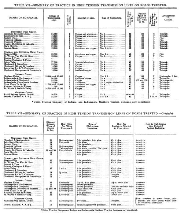
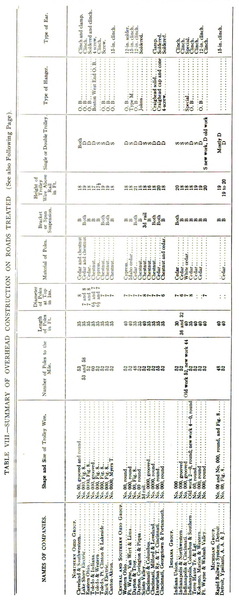
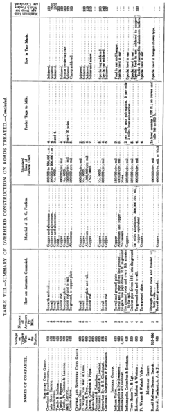
In Tables VII. and VIII. are given the details of high-tension transmission lines and overhead construction on the twenty-six roads investigated in Ohio, Indiana and Michigan. These tables are worthy of study as setting forth the latest ideas and practices in designing transmission lines and overhead construction for interurban roads.
