[Trade Journal]
Publication: Street Railway Review
Chicago, IL, United States
vol. 14, no. 5, p. 297-299, col. 1-2
SOME EXPERIENCE WITH HIGH TENSION TRANSMISSION LINE
BY H. C. REAGAN, E. E.
Upon the many high-tension systems now in operation throughout the United States, there are many and varied experiences by throe having charge of such systems. High-tension transmission is ideal, and has so demonstrated itself in practice, but the one great question in the construction of such lines is that of insulation, as a very small leak will cause trouble and increase until a short circuit is established. These troubles with high voltages are more apparent where only a single transmission line is used, as in this case such troubles are apt to tic up a whole railway system using rotary transformer sub-stations. Various conditions affect the insulation of a line, such as climate, quality of insulators, workmanship and location. The following experiences which have come under the observation of the writer will undoubtedly be of interest to other workers in the same field.
 |
| Fig. 1. |
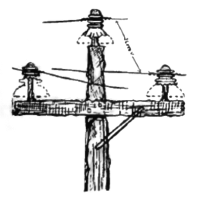
Fig. 1 shows the condition of the insulators on a transmission system due to weather conditions. This system carried 26,000 volts for 50 miles, and at this time a heavy rain occurred which gradually ceased, and was followed by a dense fog, with lower temperature. After this it again began to rain and freeze until the insulators were in the condition shown in the illustration. They were coated with ice and icicles formed between them and the cross arms. The current was on the line and the system was in operation continuously during this storm. The weather continued cold during the day so the ice did not melt until after the shutting down of the system at night, when it rained again, thus melting the ice and clearing the line. This demonstrates the high degree of insulation of ice in a dry condition.
 |
| Fig. 2. |
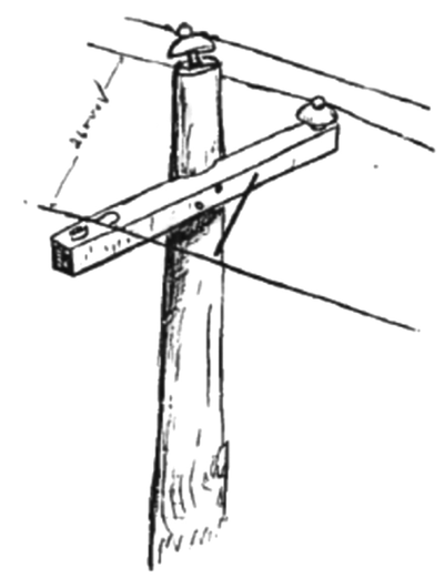
An opposite condition to that just described, one of extreme heat, is illustrated in Fig. 2, which shows what very unfavorable conditions a transmission line may meet without failing. This line was carrying 26,000 volts, and was supported by Hemingray glass insulators. The pole shown herewith stood close to a switch tower at the crossing of a steam and an electric road. While the signal man was out putting up signal lamps, the switch tower caught fire and quickly blazed up, due to the oil stored in the basement. The flames mounted to the roof of the tower, and set fire to the pole, with the result that the pole, cross arms and pins were charred and quite deeply burned. During this time the current was on, not-withstanding the heat became so great that the petticoats of the insulators all dropped, leaving only the knobs in position. Although new insulators could not be supplied for two days, the knobs which held the line proved sufficient, and no trouble with insulation was experienced.
 |
| Fig. 3. |
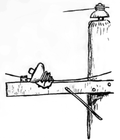
Fig. 3 shows a condition that could exist only under peculiar circumstances, and is no doubt a rare occurrence. In this case a current of 26,000 volts was carried on a bare cross arm. The line inspector reported that an insulator was missing from a cross arm at a point 30 miles from the power station, and he wanted to know if there had been any trouble indicated at the station. The writer had not seen any indication, of trouble, as the system was in full operation, and the report was attributed to an oversight. The same conditions continued for about five days, when it was again reported that an insulator was missing at the same point and that one phase of the line was lying down on the cross arm. The writer visited the pole reported and found the report correct. The pin was charred at the up and the insulator had burst and fallen entirely out of the tie wire. The line wire had fallen toward the pole with the tie wire in the position shown, but there was no sign of burning at that point. The probable reason for this not forming a short circuit is due to it being summer time, and as there had been a scarcity of rain everything was extremely dry. The paint at this point also had a hard varnish-like surface, and these two conditions made such a condition possible where a little moisture would have caused a short circuit.
 |
| Fig. 4. |
One day in the fall a condition occurred which is illustrated in Fig. 4. There was a short circuit on the line which pulled every circuit breaker out. After waiting some little time for developments, it was concluded to throw the current on, to see if the short circuit had burned off. The sub-stations cut the line out in sections, and all the sub-stations started except the last one, which again threw out the system. After awhile another effort was made to start, and everything went smoothly. Having thus located the supposed short circuit, the writer patrolled that section of the line with the inspector, desiring to see just what had caused the trouble. The illustration shows what it was. The pin was undoubtedly defective when put up, and there was an inward strain on the wire due to the pole being somewhat out of line with the others The pin broke and strangely the insulator just turned over without falling off the cross arm. The tie wire which came in contact with the cross arm caused a short circuit which burned a hollow place in the arm, and the insulator just bridged this hollow place. The second short circuit burned the cross arm so that it cleared the tie wire, after which the current stayed on the line on without further trouble.
 |
| Fig. 5. |
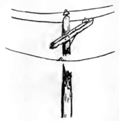
A heavy short circuit occurred on the line one afternoon, throwing nut the whole system. After a short time the sub-stations were notified to prepare for the current, starting with the first station nearest the power house. All went well until the last line switch was thrown in, when a short circuit again occurred, but not so severe as the first time. The second time the current remained on, although when the wind began to blow slightly during the night there were indications of a swinging short circuit at times, but not enough to pull out the oil switches. The next morning the inspector reported a pole burned off completely, as shown in Fig. 5. It appears that an insulator broke, causing the wire to burn off the end of the cross arm. The wind then caused the wire to swing to and fro against the pole, until the pole was completely severed as shown, the other two wires supporting the cross arm and top of the pole.
 |
| Fig. 6. |
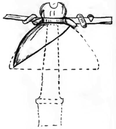
Fig. 6 shows a very had break in an insulator, which caused the death of a man. The writer was seated at his desk in the power house when all the switches on both the a. c. and d. c. switch boards came out. This occurred about 7:30 p. in. When the switches were thrown in there was no further trouble. A report came in that a man had been killed, and on going to the spot it was found that an insulator broke on a corner pole as shown in the illustration. This was the inside wire of the curve, and the strain on the wire broke the knob and a portion of the bell of the insulator. The wire dropped across the corner of a lot and swung about three feet from the ground, and a man crossing the lot after dark walked against the wire, which came across the upper part of his body and death occurred instantly. The main point to be emphasized in this case is the design of the insulator, which is a poor one. It will be seen by the dotted line that the pin did not project up into the knob or beyond the tie wire. This makes a weak construction. All pins should project beyond the point where the wire is tied to the insulator, as this gives a support to the insulator instead of throwing all the strain on the glass alone. The upper piece of the insulator was attached to the wire as shown in the illustration, the remaining portion being on the pin.
 |
| Fig. 7. |
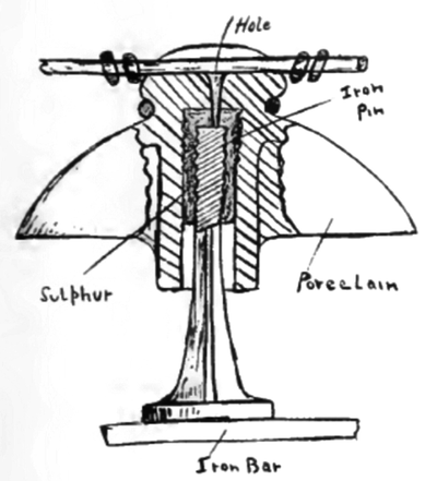
Fig. 7 shows a porcelain insulator, which had withstood a high test, but which caused a serious amount of trouble. Insulators of this pattern were installed in the sub-station and the main power station in the buss bar compartments, and on the outgoing lines. Trouble began when lightning storms occurred. These insulators were mounted on iron pins which were bolted to iron bars or frames, and the iron pins were cemented to the insulators with sulfur. The trouble started with the season of lightning storms, and to say that it was a puzzle to find the trouble, would be putting it mildly. The outward appearance of the insulator did not indicate any defect whatever, and the reason for this is plain, as the puncture was in a hard place to find, directly under the wire and over the top of the iron pin. The illustration shows the location of the puncture. The hole was about the size of the lead in an ordinary pencil, being a little wider at the opening near the wire, and tapering at the lower end near the pin. This caused a dead short circuit. The porcelain would be fused as clean as if drilled, and around the hole would be found fused copper run into the glazing. The sulphur was burned black, forming a direct path to the pin. The trouble was at first located by watching the insulators for a flash whenever the circuit was thrown on, but this was very difficult to detect. It occurred to the writer that the pin subject to short circuit must be warm, and this proved correct. After this we felt of the pins to detect any rise in temperature, and never failed to find the punctured one in this way.
 |
| Fig. 8. |
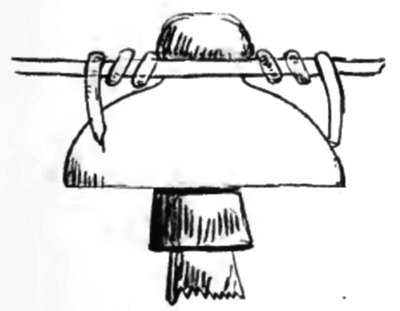
A very common and serious mistake in tying high tension lines on the insulators, is shown in Fig. 8. The ends of the tie wires are left so long that they are bent down and touch the insulator near its edge. This has the effect of reducing the striking distance between the line and the ground by virtually bringing the line to the edge of the insulator. This is bad practice, and should he avoided in high tension installations.
 |
| Fig. 9. |
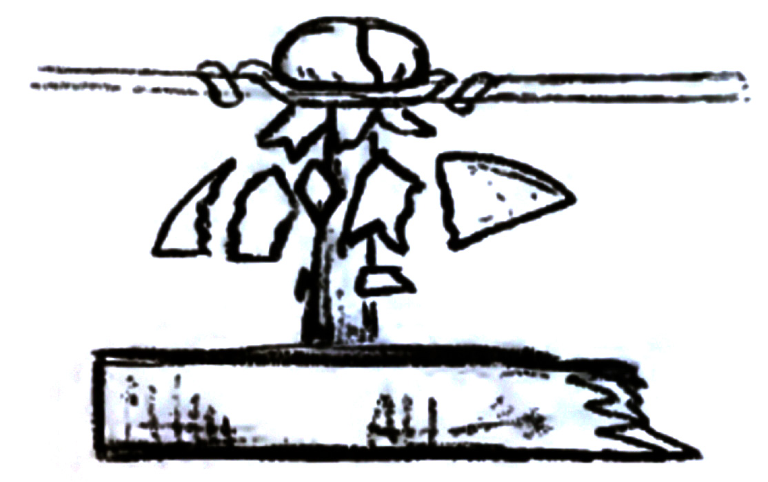
Fig. 9 illustrates a peculiar phenomenon which was observed by the writer while connected with a system on which sonic new insulators were installed. These insulators cost a little less than some of the standard makes, and there was about 50 miles of them in use. It was found, however, that these insulators would frequently burst with a loud report and in consequence the 50 miles of line had to be rebuilt with another make of insulators.
The cause of the trouble was that the insulators were not properly annealed during manufacture.
 |
| Fig. 10. |
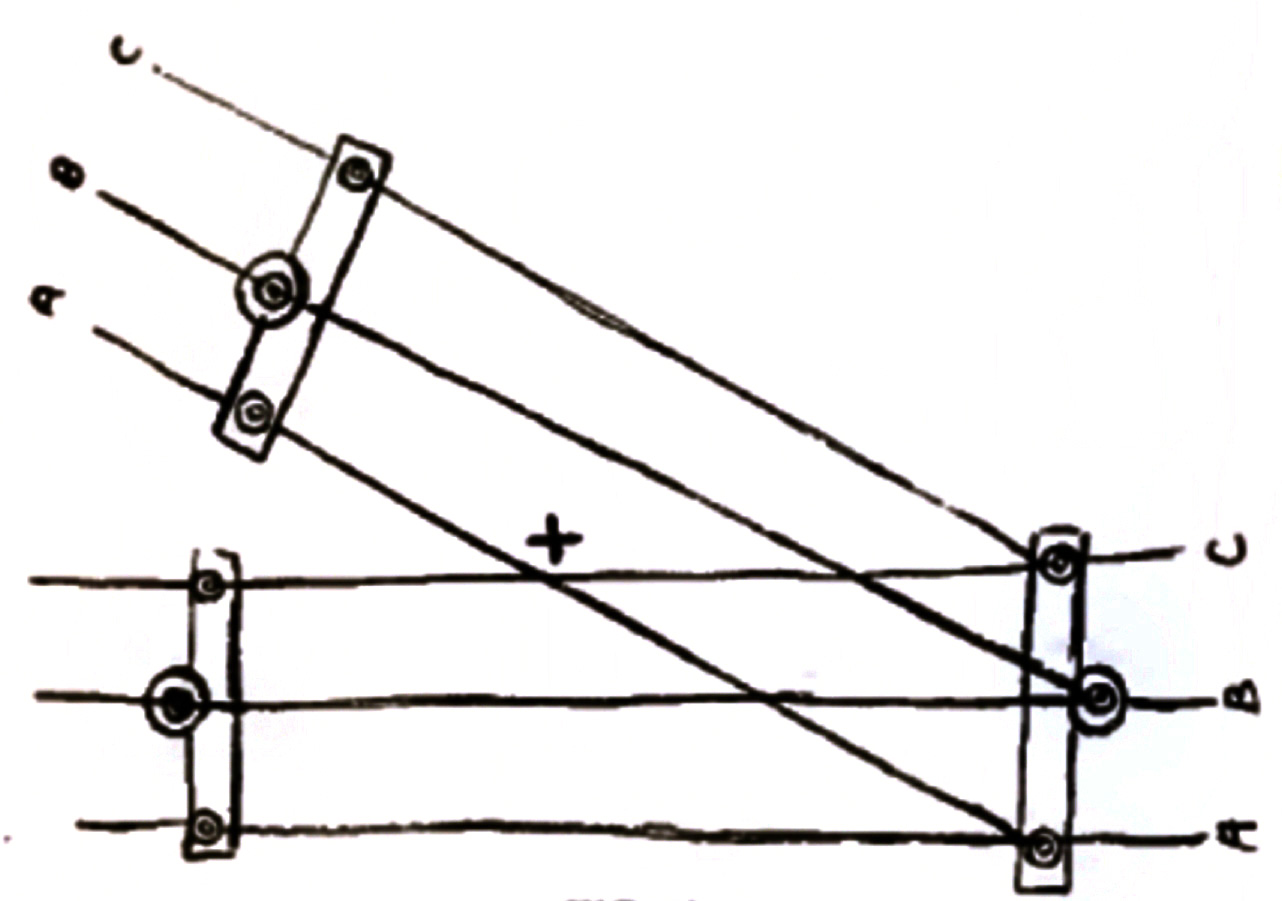
A peculiar short circuit which occurred on a 26,000 volt line was observed by the writer during the summer season in a western state. The peculiarity of the short circuit was that it would come on the line about 4:30 p m. every day. It was at first thought that the line came in contact with trees on which moisture had collected, but on inspection no such condition was found. When the short circuit again occurred it remained until after the sun came up the next morning. The line was again carefully inspected, but no trouble could be found. When the writer was about ready to give up the search and wait for results, being about 15 miles from the power station and at a junction of two divisions of a high tension system, a small boy in passing said: "Say, mister, you ought to see, the fireworks up there last night." That was the information desired, and the diagram, Fig. 10, shows what the trouble was. Where one division of the line left the other, the wires crossed at an angle of about 45 degrees. This caused the two outside phases to cross each other at the point marked +, one wire being about 18 in. above the other in the middle of the day.
When the sun shone on the wires the expansion caused them to sag considerably, but as the afternoon grew cooler, the wires would contract until the two lines came into contact, or so near it that they touched when swayed by the wind. The wire C was dropped lower down and there was no more trouble. This short circuit was difficult to detect, from the fact that there was very little burning owing to the perfect contact.
