[Trade Journal]
Publication: The Carnegie Institute of Technology Technical Journal
Pittsburgh, PA, United States
vol. 1, no. 2, p. 27-32, col. 1
THE MANUFACTURE OF HIGH TENSION PORCELAIN INSULATORS
G. M. Whistler, '20
High tension porcelain insulators find their greatest field in transmission of power over considerable distances and at considerable voltage. Both the increasing pressures and distance have led to a very great improvement over the early insulators.
The earliest development of power or rather electrical transmission is credited to the early experimenters who developed telegraphy.
In 1842 English patents were granted to a man named Cooke covering a system of insulated suspended wires. The first American use came probably with the Baltimore-Washington line, built by Prof. Morse in 1843.
Power was first transmitted over a 37 mile telegraph line in 1882 at 1300 volts by Deprez who sent a fraction of a horse power. Then followed the Lauffen-Frankfort 40 cycle, 3 phase line, 100 miles long in 1891. This was in many ways an experiment but it gave good promise of results and power systems developed more rapidly.
The power and economic opportunities in the United States and Canada have resulted in a very rapid growth of long distance and high tension lines.
A few which followed are tabulated below.
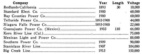 |
From this table we see that the possible voltage for transmission systems has jumped from 10 to 150 K.V. in only 20 years. In this same period insulators had to develop in advance of voltages and they did. Insulators grew from a small unit the size of a baseball to a length of over four feet which required as much as 600,000 volts to flash over.
Insulating Materials
Glass and porcelain have found the greatest favor in the development of insulators. Both are used, but only the porcelain has found use in the high tension insulators now demanded.
Porcelain can be worked quite easily to almost any desired shape; it is mechanically strong as well as electrically; it is not affected by either electrical or weather forces and is the one material which meets all the specifications for transmission work.
Electrical porcelain is made up of flint, feldspar, china clay and ball clay. The flint used is a very finely ground or powdered material from quartz rock or sand. Chemically it is almost pure silicon dioxide. The flint is abundant and no trouble is met in its purchase except an examination for fineness and moisture content.
The feldspar is the active material of the body during burning; much more care being needed to be sure it is not adulterated with flint, because both look like white flour. Feldspars are alkaline aluminum-silicates and are rich in soda or potash or both.
Both the clays (china and ball) are the kaolins. In general, clay is merely a product of weathered feldspar. China clay is coarse grained but burns to a whiter color than ball clay which is of fine grain. The china clay is given preference in the body for dishes but ball clay is best for electrical purposes because of its finer grain. It also makes a more easily worked body than the china clay.
Preparation of the Material for Use
From the bins about a ton batch of the four materials is weighed and dumped into the blunger which is a large power driven churn. Since the clays are in lump and ball form and are hard to break up they are put in first; the feldspar and flint not following until the clays and water are well mixed. After several hours in the blunger the mixture has a thick creamy nature and is called slip. The slip is now allowed to run over a very fine mesh screen which removes all gravel, coarse grains, twigs and dirt in general. The screens are kept in motion all the time to prevent the fine mesh from becoming plugged. From this the slip flows to storage cisterns in which paddles are revolving to prevent any settling of the ingredients. As the slip is needed it is pumped from the cistern into the filter presses which force out the water and allow the body of the four materials to remain in a well mixed form. The water filters through a double layer of heavy canvas. This process takes several hours. On the completion (indicated by a pressure gage on the pump line) of the filter process the press is released and the cakes of the body can be removed to a storage room where they are pounded down into a compact mass by means of large wooden mallets.
While the clay is stored here the remaining water permeates it uniformly. This is called the ageing process. As the clay is needed for shaping, this stock is used. It is placed in a pug mill which forces it out in a cylinder of about eight inches in diameter which is cut in 18 inch lengths as it comes out. This pug mill works much the same as a sausage grinder, only it forces the clay out in a compact mass in one cylinder instead of through many fine holes.
Shaping the Ware
In shaping the ware there are two main processes in use.
I. The Wet Process
Under this process comes all the work on High Tension Insulators and all tube work. This process uses the clay as it comes from the pug mill while in a plastic state.
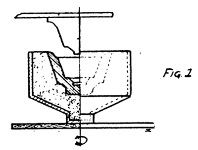 |
II. The Dry Process Under this process comes all low tension porcelain which is made from the dry clay which is forced into the mold in a compact mass. The dry clay feels like a slightly moist dust or fine powder. This type of porcelain is seldom used for voltages above 1000. It has a coarse grain fracture and is very porous when compared with the wet process porcelain. As the clay comes from the pug mill in the 18 in. x 8 in. cylinders it is moved to the jigger department. The jigger is merely a plaster of paris mold rotating in a horizontal plane. Two men work at each jigger. One man cuts the clay into workable sizes; places it in the mold, which has generally the shape of the top part of the insulator or part of the insulator made. The man at the jigger then places the mold in the rotating support and shapes the clay with his hand, first roughly, and then finally by dropping or forcing a wooden shaping tool into the center of the mold. (Fig. 1.)
 |
The plaster of paris mold with the shaped piece still in, is carried to a drying room where it is placed on racks and allowed to remain until dry.
After drying, the next process is removing from the mold and giving such additional shaping as is necessary and which could not be given by the mold and jigger tool. When this has been completed the ware is next dipped in a milky solution consisting of the same ingredients as the body but in such proportions that the glaze melts before the body. The glaze for most low tension materials is white while for most high tension work it is brown; the color being given by some added coloring oxide.
The glaze is necessary, for, unless glazed, the porcelain presents a rough surface which would catch and hold dirt. The glaze adds nothing to the insulating value nor does it seem to prevent moisture from entering a porous sample. The color is important inasmuch as it renders the insulator inconspicuous and makes it a less tempting target for bullets and stones.
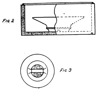
As soon as the glaze has dried the ware is packed in saggers which are coarse crock like containers in which the ware is fired. (Fig. 2.)
Figure 3 shows the top of a typical piece of ware as it is coated with glaze. On all porcelain ware some part must be left unglazed in order that it will not fuse onto the sagger during burning. The shaded portion indicates the unglazed part on the head of an insulator.
As the saggers are packed there is put around the edge a roll of packing made of clay and one sagger is placed on top of another in the kiln. This roll of clay makes a more stable pile of saggers and prevents the sulphur vapor form getting to the glaze which it discolors during burning. For this reason, where coal is used for firing the kilns, the sulphur content should be low. When the kiln is filled the door is closed with brick and clay and the fire is started. The firing covers a period of several days. The rate of temperature rise and firing control is accomplished by the aid of peep holes which open in on pyrometer cones whose melting points are known. Three cones are generally used and melt at temperature differences of about 20 deg. C. or 36 deg. F. If the first cone melts and bends over and the second cone just starts to melt the ware is correctly fired. If all three bend over it has been over fired. If the first only bends it has been under fired.
In addition to this, pyrometers are used which tell just what is going on in the kiln. Several pyrometers must be used to a kiln as conditions are different in different parts of the kilns.
In order to eliminate this feature and assure that all insulators have the same heat or burning, one company has developed a tunnel kiln. The saggers are stacked on cars and the cars run through the kiln at such a speed that they reach, remain in and leave at such a speed as to bring the ware up to its burning temperature at a proper rate, burn a proper length of time and cool slowly on leaving the hot zone of the tunnel. This method has the advantage in that it is continuous in operation and should be more economical in fuel consumption. In firing an ordinary kiln there is considerable heat loss due to heating up the entire kiln and then allowing it to cool again.
After the insulators come out of the kiln they are given a thorough inspection; those which have become warped, cracked or have defective glazes are scrapped. As they are being removed, the cones are used as a guide to under fired and over fired samples and these are scrapped as well. An under fired sample is more difficult to pick out than one which is over fired. The over fired samples or parts show small blisters on the surface. Some companies i. e., R. Thomas and Sons Co., use a glaze which is a rich mahogany brown when properly fired. On under firing this glaze is very light brown, verging on to the yellow. On over firing this color turns an olive green so that they can tell at a glance just about to what degree an insulator has been fired. In the shop these three conditions are called over fire, normal fire and easy fire. The General Electric Co, uses a glaze which gives the same finish regardless of the fire. This is good for appearance but it loses that index which should be of more value than appearance.
The Routine Test
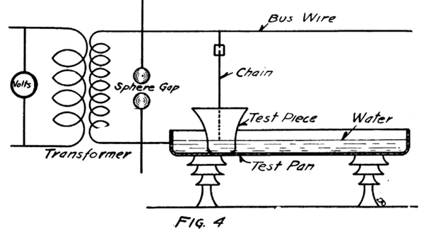
After inspection has of insulators have to be The Routine Test culled out the defective units, the insulators or parts given the pan test. (Fig. 4.)
The ware is placed head down in a long, wide pan which will accommodate 20 to 60 units at a time, depending on the size. The pan contains water which assures a better contact. Above the pan runs a high tension bus wire from which chains are dropped into the inside of the test pieces. At the point where the wire and the chain connect there is a minute gap which shows a blue spark for each chain as long as the test is on and as long as there are no defective pieces in the pan. As soon as anyone punctures, the voltage drops on all the other units, and the blue spark disappears, only a yellow spark shows on the defective unit. The defective units are removed as they fail and the test is run all the way from one to five minutes at flashover voltage after the last failure. Each part of an insulator is given this test; then the parts are assembled and a second test is given the assembled insulator after the cement has had time to set well. The cement used is neat Portland cement.
 |
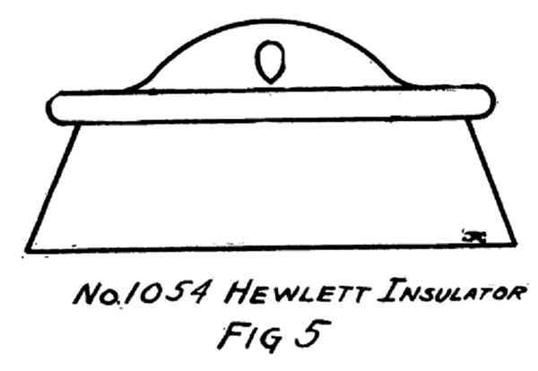
All the routine tests are of this same nature; the only difference being in the method of making the two contacts i. e. , in the case of the No. 1054 Hewlett Insulator (Fig. 5) spiral springs are inserted in the two link holes. The springs are very much like those in window shade rollers; they are cut so as to be about 6 inches long and have the chain connected at the mid point.
 |
This type of insulator and most of the suspension type are given both the 60 cycle and the high frequency test at flashover.
Of course the test given an insulator may vary depending on what the purchaser demands. As the test specifications become more rigid and time consuming the cost of the insulator increases accordingly.
