[Trade Journal]
Publication: Street Railway Review
Chicago, IL, United States
vol. 12, no. 8, p. 441-459, col. 1-2
The Aurora, Elgin & Chicago Railway.
|
The Aurora, Elgin & Chicago Ry., which is now practically completed, constitutes one of the most important suburban electric railway undertakings which has been attempted up to the present time. This road covers one of the most populous suburban districts in the neighborhood of Chicago, and with nearly 100 miles of its own track and physical connections with several other suburban electric railways the system will serve some twenty cities and towns outside of Chicago having an aggregate population of about 150,000, some data as to the distribution of which will be given in another place.
The construction of this road, including the roadbed, power house, sub-stations, and line work, has been designed in a most careful and substantial manner and no expense has been spared to make every detail of the installation as complete and thoroughly up-to-date as possible, and in all of its engineering features this road represents the most modern and approved practice. It is a third-rail system throughout and the curves and grades have been laid out with the idea of operating a high speed schedule.
| |||
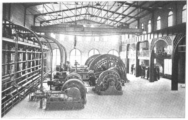
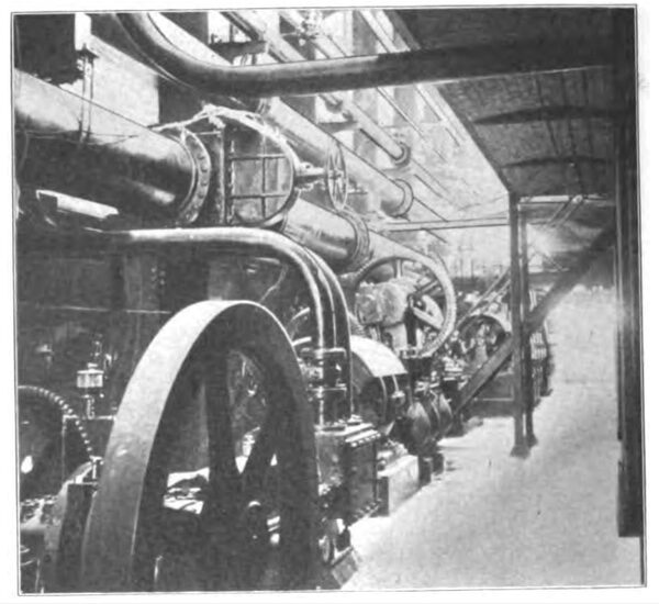
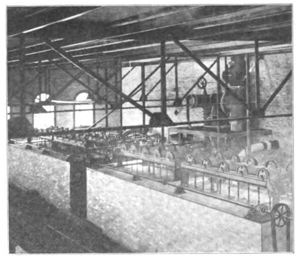
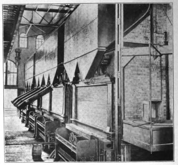
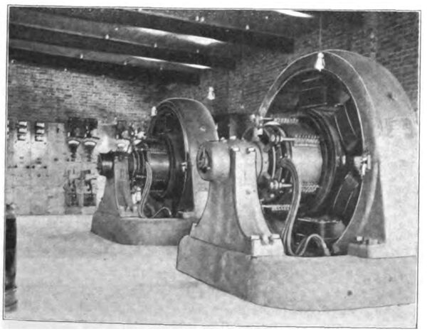
| General View of Engine and Generator Room, Power Station, Batavia, Ill. |
The road passes through a picturesque section of country which, though served by the suburban lines of several steam railroads, is still greatly in need of more frequent and rapid service. The passenger traffic between all of the suburbs reached by this road and Chicago is capable of vast expansion, but it is at present greatly hampered by the time necessarily lost in making connections between the different steam road branches now operating in this territory, so that at certain times of day a trip which should be made in an hour or less is frequently protracted to two or three hours. By furnishing a frequent and rapid service, as is designed by the Aurora, Elgin & Chicago, the transportation facilities of these suburbs will be vastly improved and a large proportion of the traffic of this territory is certain to be diverted to the new line.
This enterprise has been developed by Cleveland men, and they have acted on what we believe deserves to be called the "Cleveland principle" that for the security of investors and permanency of the road an electric railway company should own its right of way in fee, or at least have a perpetual easement in the realty occupied by its tracks. With the exception of the city street crossings the company owns the fee of all of the right of way. In the country the strip of land is 100 ft. wide except for a few short stretches, which aggregate perhaps half a mile in length, where the width is 66 ft. In all cities and villages the company bought either the whole or portions of the lots necessary to give it a complete way, in many cases moving or wrecking the improvements on the realty. Being organized under the railroad law the franchise question has no terrors for this company.
The company owes its origin and the successful completion of its plans principally to Mr. L. J. Wolf, of Cleveland, who has been ably assisted by Messrs. Will Christy, of Akron, O., and Charles Jones, of Wheaton, Ill. Mr. Wolf has for years been prominently identified with electric railways, and is at this time president of the Springfield & Xenia Traction Co., which is now building an electric line between Springfield, O., and Xenia; vice-president of the Western Ohio Railway Co., of Cleveland, and president of the Elgin, Aurora & Southern Traction Co. and of the Aurora, Elgin & Chicago. Mr. Christy is one of the pioneers in interurban electric railroading, having been for some years the manager of the Akron, Bedford & Cleveland, which is now part of the Northern Ohio Traction Co's. system; after leaving this company he, with Mr. M. J. Mandelbaum, of Cleveland, effected the consolidation of the Dayton Traction Co., the Cincinnati & Miami Valley Traction Co., and the Cincinnati, Hamilton & Dayton Electric Railway Co., forming the Southern Ohio Traction Co. Mr. Jones was connected with the construction of the Lorain & Cleveland Ry., which it will be remembered, for some time held the record for high speed on electric lines, and was formerly one of the engineers of the Lorain Steel Co., at Lorain, Ohio. Mr. E. H. Arnold, who has had immediate super-vision of the construction on the Aurora, Elgin & Chicago, was assistant chief engineer on the Lorain & Cleveland, and has had an extended experience in electric railway work.
The company is a consolidation of the Aurora, Wheaton & Chicago Railway Co., the Elgin & Chicago Railway Co. and the Batavia & Eastern Railway Co., and the officers are: President, L. J. Wolf; vice-president, M. H. Wilson; secretary, Harry Greenebaum; treasurer, M. J. Mandelbaum. The capital stock is $3,000,000, one half of which is preferred, and there were authorized $3,000,000, in 5 per cent gold bonds, to be issued as needed for construction.
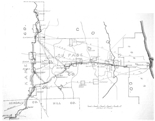 |
| Map of the Aurora, Elgin & Chicago Ry. and Connecting Lines. |
The construction force comprised Will Christy, president of the Cleveland Construction Co., who was general manager during construction; W. E. Davis, vice-president of the Cleveland Construction Co., consulting electrical engineer; Chas. Jones, chief engineer; E. H. Arnold , construction engineer; Ernest Gonzenbach, electrical engineer; W. L. Morris, mechanical engineer.
The operation of the road will be in charge of Mr. Warren Bicknell; the operating staff will include C. E. Flenner, auditor; W. W. Crawford, superintendent of transportation; Ernest Gozenbach, electrical engineer.
The route of the Aurora, Elgin & Chicago Ry. and the steam railroads with which it will be in competition in the territory served are clearly shown on the accompanying map. From the Union Loop, Chicago, to the terminal of the Garfield Park branch of the Metropolitan West Side Elevated Railway at West 52d Ave.is a distance of 6 1/2 miles, the schedule time between these points being 26 minutes. From West 52d Ave., the eastern terminus of the Aurora, Elgin & Chicago, this line is a double track road for 21 miles to the Chicago Golf Club near Wheaton. From Wheaton there are two branches, one northwest to Elgin, 16 1/2 miles, and one southwest to Aurora, 14 1/2 miles, making the road from the eastern terminus to Aurora 33 miles long. Another branch from the Aurora fork runs to Batavia, 7 miles from the junction. Of the 56 miles of road, 21 miles are double track and in addition there are long sidings, one of 1 mile, one of 1 1/2 miles, two of 1,500 ft. and three of 800 ft., which will bring the total to 82 miles measured as single track.
| |||
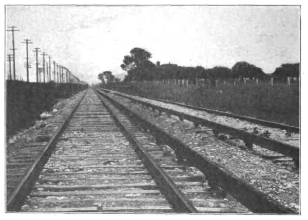
| View on Cook County Line. |
The running time from Aurora, Elgin or Batavia to Chicago will be 45 minutes for express trains and one hour for local trains. The schedule contemplated is a train each way every 15 minutes between Chicago and Wheaton, half running to Aurora and half to Elgin, thus giving a half-hourly service on those two branches west of Wheaton. On the Batavia branch cars will be run at 30 minute intervals connecting with Aurora and Chicago trains at Eola Junction. The maximum number of cars per train will probably be four.
The rates of fare have been adjusted so as to be somewhat less than the lowest commutation rates of the competing steam lines. The principal distances and rates of fare, in cents, are as follows:
From W. 52d Ave., Chicago, to
Distance, Single Round
Miles. Fare. Trip.
Austin Ave......................................... 1 5 10
Oak Park............................................ 2 5 10
Harlem............................................... 3 5 10
Maywood.......................................... 4 1/4 5 10
Bellwood........................................... 4 3/4 10 20
South Elmhurst.................................. 9 3/4 15 25
Lombard............................................ 14 18 30
Glen Ellyn......................................... 16 1/2 20 35
Wheaton............................................ 19 25 45
Chicago Golf Grounds...................... 20 30 55
Warrenville........................................ 23 3/4 40 75
Eola Junction..................................... 27 3/4 45 80
Aurora............................................... 33 50 90
Batavia.............................................. 33 3/4 50 90
Children over six years and under twelve years of age are entitled to half-rate tickets. No fare is charged for children under six years of age when accompanied by an adult. The half-fare rates are about one-half that given in the table.
At Elgin and at Aurora physical connection is made with the tracks of the Elgin, Aurora & Southern Traction Co., which is a consolidation of the companies along the Fox River from Carpentersville to Yorkville, via Dundee, Elgin, Clintonville, St. Charles, Geneva, Batavia, Aurora, and Oswego. The Elgin, Aurora & Southern system includes the Carpentersville, Elgin & Aurora, the Aurora & Geneva, and the Aurora, Yorkville & Morris Railways, and is controlled by the same interests as the Aurora, Elgin & Chicago.
The steam railroads in the territory are the Chicago, Milwaukee & St. Paul to Elgin; the Illinois Central; the Chicago & Northwestern to Wheaton, Geneva and Batavia; the Chicago Great Western to St. Charles; the Chicago, Burlington & Quincy to Batavia and Aurora; the Elgin, Joliet & Eastern to Aurora.
The population of the towns outside of Chicago served by the Aurora, Elgin & Chicago Ry. is as follows:
Austin................................................ 15,000
Oak Park............................................ 10,000
Harlem............................................... 3,500
Maywood........................................... 4,500
Melrose Park...................................... 2,800
Bellwood............................................ 200
Elmhurst............................................. 2,000
Lombard............................................. 700
Glen Ellyn........................................... 900
Wheaton............................................. 3,000
Warrenville.......................................... 500
Eola...................................................... 200
Aurora.............................................. 30,000
Batavia............................................... 4,500
Elgin................................................. 30,000
_______
Total................................................ 107,800
To these may properly be added the population along the Elgin, Aurora & Southern as follows:
Carpenterville................................... 1,800
Dundee............................................. 2,900
Clintonville........................................ 600
St. Charles........................................ 3,200
Geneva.............................................. 3,000
Montgomery...................................... 500
Oswego.............................................. 800
Bristol................................................ 600
Yorkville........................................... 1,200
_______
Total................................................ 14,600
In addition to this there is in the territory west of the Fox River and within 40 miles of Aurora, Batavia and Elgin, and tributary to them a population of about 200,000.
Tracks and Bridges.
The route for the Aurora, Elgin & Chicago was chosen only after a most careful survey of the territory as the object was to build a line on which trains could be operated at high speeds. With the exception of the curves near Chicago, which were rendered necessary to avoid crossing streets at angles so acute as to make undesirably long breaks in the third rail, the curves are struck with long radii, and are connected by long tangents. The maximum grade is 1.8 per cent for about 1,000 ft., this being necessary to get down into the Fox River Valley; none of the other grades are above 1 per cent.
| |||
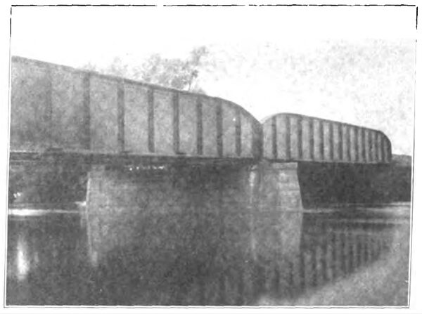
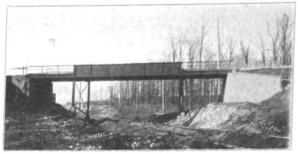
| Bridge Over Des Plaines River. |
The track standards are shown in one of the accompanying engravings. The line is laid throughout with 80-lb. T-rail of the A. S. C. E. standard section, in 60 ft. lengths. The joints are made with 28-in. 4-bolt splice bars; the bolts are 1 in. in diameter by 4 in. long. Ties are spaced 2,840 to the mile, each fifth tie being of oak 6 x 8 in. x 9 ft., for the support of the third rail insulators. On tangents the other ties are of cedar 6 x 8 in. x 8 ft., and on curves of oak of the same dimensions. The entire line is gravel ballasted except on the sections near the Fox River, where crushed stone is used.
| |||
| Cattle Pass at South Elmhurst. |
The conductor rail is of T-section, 100 lb. per yard, of a special soft steel, 0.10 per cent carbon; the rail is 5 1/2 in. high, the head being 2 1/2 in. wide and the base 5 1/2 in. It is supported with the inner flange of the head 19 1/8 in. from the gage side of the service rail, and on insulators which bring the top of the rail 11 3-16 in. above the ties. On that portion of the line first built the third rail insulators are paraffined wooden blocks with foot stands and top plates of malleable iron, but the standard adopted for future work is a malleable iron insulator designed and patented by Mr. Gonzenbach, which is shown here in vertical section. The insulation collar, circular in plan, is made of "Dirigo" and sets on top of the circular malleable iron base; the malleable iron cap fits over this and has two bearing strips for the rail and two vertical lugs to prevent lateral displacements. These insulators were made by the Ohio Brass Co. The weight of the rail is relied upon to hold it in position and no fastenings are provided; the insulator bases are secured to the ties by two railroad spikes.
At highway and railroad crossings the rail is broken and the car runs the crossing under its momentum. These breaks in the third rail vary from 26 ft. to 100 ft., according to the conditions, there being but two breaks of 100 ft. Wherever there is such a break, the sections are connected by cables laid 3 ft. underground and covered by planks. These cables are of copper and were furnished by the American Steel & Wire Co.; they are of three sections, 1,500,000, 1,000,000 and 500,000 c. m., the heaviest section being used for a distance of about two miles on either side of the sub-stations, the one million section for succeeding distances which are about six miles, and the lightest cables are used at special work. The cables first ordered were rubber insulated but later a paper insulation cable was adopted as the standard.
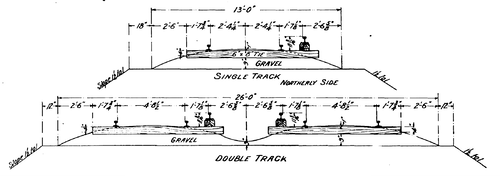 |
| Track Standards for Aurora, Elgin & Chicago Ry. |
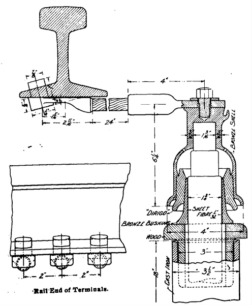
These cables are soldered into terminals, made by the Ohio Brass Co. according to the design of Mr. Gonzenbach. From the cable terminal to the conductor rail connection is by a three-branch stub end bond 24 in. long made by the Protected Rail Bond Co., of Philadelphia. The cable terminal (including the wooden bushing and the cast iron pipe for protecting the cable where it enters the ground) and the bond terminals are shown in detail in the line drawings. The three bond terminals for connection to the rail are spaced about 2 in. between centers, the holes being drilled in the inner bottom flange, thus making available a large contact area between the bond and rail.
The space between the cable end and the bronze terminal shell is filled with paraffine. The cast pipe which protects the cable end is fastened to a 4-ft. post, the pipe having a band cast on it under which a strap can be conveniently placed.
 |
| Gonzenbach Cable Terminal and \"Protected\" Terminal Bond. |
The sections of conductor rails are provided with cast tips 28 in. long which serve to guide the contact shoe into position on the 100-lb. rail and the adjacent rail, 33 ft. long, is also given an inclination of about 2 in. A drawing of this tip is shown herewith. The splice bars for the conductor rail are similar in design to those used on the Manhattan Ry., New York City, and which were illustrated in the "Review" for December, 1900, page 708. These bars are 8 3/4 in. long, with two bolt holes 1 1/8 x 1 3/8 in. spaced 6 1/4 in. between centers and were made by the Ohio Brass Co. and the Ludlow Supply Co. At each joint of the conductor rail are two 7 in. 500,000-c. m. solid terminal "Protected" rail bonds furnished by the Mayer & Englund Co., of Philadelphia. The track rails are double bonded with 12-in. bonds, 1-in. terminals, the bonds being partly the "Protected" and partly the American Steel & Wire Co's. bonds.
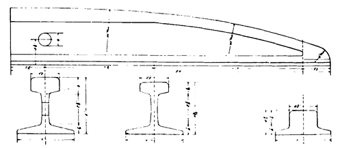 |
| Tip for Third Rail. |
At turnouts and switches it is necessary to depress the conductor rail for a short distance to permit the shoe to change its position without striking the side of the rail. For this purpose sections of the third rail are bent as shown in the line drawing of the "drop rail" and placed with its center 12 in. back of the point of double tread on the service rail switch. In addition the conductor rails for 10 ft. on each side of the 12-ft. drop section are given a slope of 1/2 in. in 10 ft., the ties being dapped where they receive the insulators.
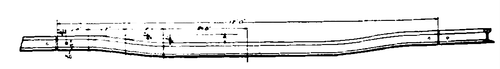 |
| Drop Rail at Special Work. |
At highway crossings vitrified clay cattle guards, made by the Climax Stock Guard Co., Marquette Bldg., Chicago, are installed. These guards are made of blocks each 24 in. long by 8 1/2 in. wide, and in section like an inverted W with walls 1 1/4 in. thick. Forty sections are required for a guard 8 ft. by 8 ft., and these are held in place by strips of wood. The Aurora, Elgin & Chicago ordered over 700 guards, which are used exclusively; the half-tone engraving of the exterior of the sub-station shows one of the "Climax" guards in the foreground.
The road being built with high speed operation in view no expense was spared to make the track the best that it is possible to build. By reason of the exceptionally heavy rainfall this season the settlement of the roadbed has been as great as would ordinarily take place in two or three years, so that when finally surfaced the track will be in perfect condition.
All the steel structures on the road are designed for a live load of two 142-ton Cooper's E-40 locomotives followed by a uniformly distributed load of 4,000 lb. per lineal foot. The steel bridges are of the deck type wherever the conditions permitted, and elsewhere are through girder bridges.
| |||
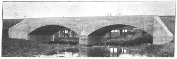
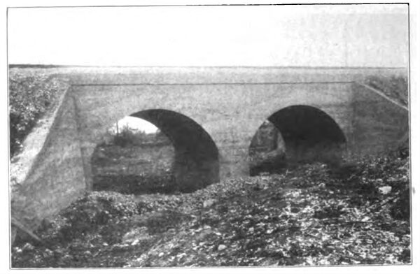
| 35-Ft. Arches of Concrete Masonry. |
The principal steel bridges are as follows: Des Plaines River, double track through girder, two 100-ft. spans. East branch of DuPage River, double track deck, one 69 1/2-ft. span. West branch of Du Page River, single track through girder, one 89-ft. span, in con-junction with a 22 1/2-ft. deck span. Lombard highway crossing, double track deck, one 36-ft. span. At three other highway overhead crossings are 45-ft. through girder spans. The Elgin branch crosses the Chicago & Northwestern tracks on a 150-ft. through truss bridge. All abutments and piers are of concrete.
| |||
| Waterway at Batavia. |
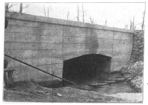
In addition to the various steel structures there are concrete arch bridges at various points. Over Salt Creek at South Elmhurst is a concrete bridge with two 35-ft. arches, and at other small streams are arches of from 10 to 15 ft . span. Views of several culverts and cattle passes are shown in the half-tone engravings.
| |||
| Crossingfor Overhead Road. |
The specifications under which the concrete work was done provide for three grades of concrete, the composition and uses of which were as follows:
Class A. Portland cement, 1 part; sand, 2 parts; stone, 4 parts. Used for arch sheeting, bridge seats and parapet walls.
Class B. Portland cement, 1 part; sand, 3 parts; stone, 6 parts. Used for abutments, bench walls for arches, and retaining walls.
Class C. Portland cement, 1 part; sand, 4 parts; stone, 8 parts. Used for foundations and other work as directed by the engineer in charge.
| |||
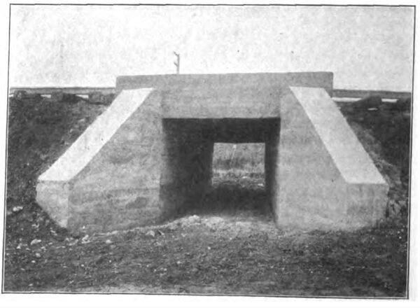
| Double-Box Culvert at Bellewood. |
The foregoing proportions are by volume, one-fourth barrel of cement as packed by the maufacturers being taken as a cubic foot, and the sand and stone measured loosely, the stone to be broken to pass a 1 1/2 in. screen.
The concrete was put down in layers of 4 in. to 5 in. in thickness and thoroughly rammed until water appeared on the surface.
In order to get into Chicago with the Aurora, Elgin & Chicago line it was necessary to cross several steam railroads at points where it was impracticable to separate the grades: At Forest Home, three miles west of 52nd St., the Wisconsin Central, Chicago, Great Western and Chicago Terminal Transfer roads are crossed; about ten miles west of Maywood there is crossing with the Chicago Junction road and at South Elmhurst with the Illinois Central. These three crossings are protected by interlocking signals, with derailing switches in both the steam and electric lines. The derailing switches are of the lifting type which leaves the track rails unbroken, this being effected by having the derailing points thrown into a position on top of the service rail; the derailing switches and split switches were made by the Morden Frog & Crossing Works, Chicago.
At intervals of four miles there are cross overs with lights. The turnouts all have spring frogs.
The right of way is all fenced with the American Steel & Wire Co's. woven wire fencing, 55 in. high with 11 wires. The posts are of cedar, 8 ft. long, with 6-in tops, set 3 ft. in the ground; they are spaced 16 1/2 ft. apart.
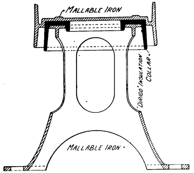 |
| Gonzenbach Third-Rail Insulator-One-Third Size. |
The eastern terminal of the road where passengers are transferred to the Metropolitan West Side Elevated Railway, of Chicago, is shown in one of the line drawings. The Metropolitan company owns a tract of land at W. 52d Ave. on which it has constructed a terminal loop at grade, the elevated structure being reached by an incline extending between 48th Ave. and 52d Ave. The Aurora, Elgin & Chicago double track line crosses the Metropolitan loop at grade, the platforms for transfer of passengers being located within the loop and between the tracks of the two roads used for the same direction of traffic. A subway with stairs leading to the sidewalk in 52d Ave. and to each side of the Aurora, Elgin & Chicago tracks inside the loop gives the means of ingress and egress to passengers without their crossing any of the tracks, these being fenced in. The Metropolitan has built inspection pits and storage tracks as indicated on the plan.
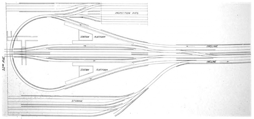 |
| Terminal at 52d Ave. |
Loop and connecting track-Metropolitan Road. Central tracks-Aurora, Elgin & Chicago Ry.
In connection with this terminal, there has recently been completed an interesting piece of engineering work that is quite out of the ordinary. When the Metropolitan incline, which is a doubletrack deck structure with four lines of plate girders, supported on transverse plate girders which rest on two rows of steel columns, was built it was necessary to make a reverse curve at the east end because the necessary rights of way for a straight track could not be secured at that time. The girders carrying the curves, however were designed for the straight line location to which it was intended to shift the structure ultimately, and extra plates spliced to the girder ends for temporary use.
| |||
| Crossing at Indian Creek, Near Aurora. |
Fortunately the Metropolitan company secured the needed rights of way and was enabled to move the incline before it was used for regular traffic. The work of moving was undertaken July 25th and completed Aug. 8th; it was done by contract under the direction of Mr. W. S. Menden, chief engineer of the Metropolitan. The three spans of the reverse curves mentioned were cut apart for removing the extra plates referred to and shifted separately. The rest of the incline, comprising 19 full spans, was moved as a whole.
In moving the structure was first jacked up some 18 in. to clear the pedestal anchor bolts and a blocking of 6 and 8 in. timbers was then built between the old and the new pedestals; two lines of 80-lb. rails were laid upon this blocking 12 in. apart and several iron rollers were placed under the base plate of each column. The structure was then ready for moving. The moving was accomplished by means of ordinary house-moving jacks, which abutted at a slight angle against the inside of each forward column in the direction of the movement, so that these columns pulled the rest of the structure as they advanced. A section of 19 spans was thus moved as a single piece and sights were taken from time to time to make sure the entire length was kept in line. The west end of the structure, which was moved the shortest distance, was first moved part of the way and the end was next moved, the two portions being moved alternately. The greatest distance any portion was moved was 40 ft. at the east end, decreasing to zero at the west end. When the columns were over the new anchor bolts the structure was lowered onto the new foundations and bolted in place.
Power House.
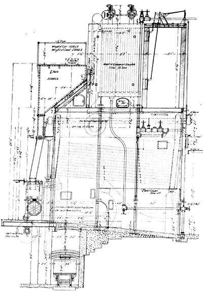
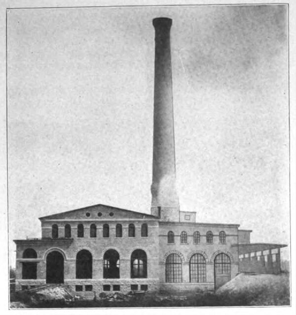
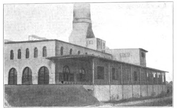
The main generating station which is at Batavia on the Fox River was designed by Mr. W. L. Morris, who acted as architect as well as engineer. The building itself is of very pleasing appearance; it is constructed of Illinois buff brick with white stone foundations and trimmings, the building, including the coal storage, being 202 ft. 4 in. x 160 ft. 6 in. The engine and generator room measures 199 ft. 6 in. x 83 ft. 5 in. and the boiler room 198 ft. 2 in. x 46 ft. 9 in. The stack is placed at the center of the length of the boiler room with one wall flush with the wall separating the boiler room from the engine and generator room. The coal storage is 25 ft. wide inside the walls and extends the entire length of the building and is divided by brick walls into 18 compartments in the bottom of each of which are two steel hoppers. Each of the 18 bunkers has a capacity of 3.771 cu. ft., and is designed to hold 100 tons of coal.
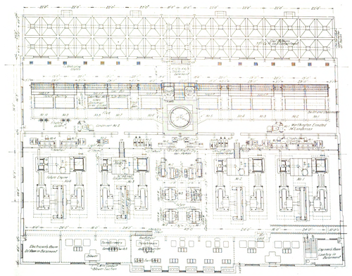 |
| Plan of Main Power Station at Batavia. |
A well defined plan has been followed in the construction of both the power station and the sub-stations. This is the transmission of all power, both steam and electrical, in one direction across the station while all the elements in a longitudinal direction are in the nature of equalizers. Thus, will be seen in the power house, first, a row of coal bunkers extending the length of the building and parallel to these are the boilers. Then comes the steam piping for the entire plant suspended on the partition wall between the boiler and engine rooms. The next row of machinery consists of pumps and auxiliary apparatus followed by the engines, then the dynamos and lastly the transformers, oil switches and cables which distribute the power. This plan of arranging the machinery is a most logical one as it permits of additions at either end of the apparatus at present installed without derangement of the general plan that is followed out.
| |||
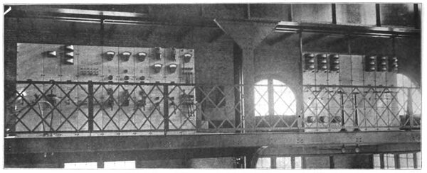
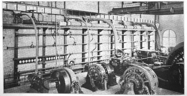
| Switchboard Gallery in Power Station. |
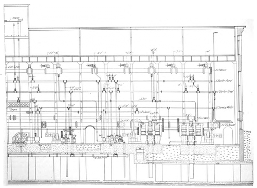
By reference to the half tone illustrations and the line drawing showing the station in section it will be seen that coal trains may be run over the bunkers and the contents dumped. In the basement, under the coal bunkers and boiler room, there are tracks of 20-lb. rails laid to 2 ft. outside gage, over which are run small cars of about 1 ton capacity for transferring coal to the boiler bunkers. The space between these track rails is filled with concrete so that there is no chance for dirt to accumulate and a better footing is afforded for the men handling coal. Two transverse tracks at the center of the building lead to two elevators located in front of the stack on which the loaded cars are lifted to a longitudinal track running above the boilers. In front of and over each boiler is a steel bunker holding from 5 to 7 hours' supply of coal, the coal being fed down through chutes to the furnaces.
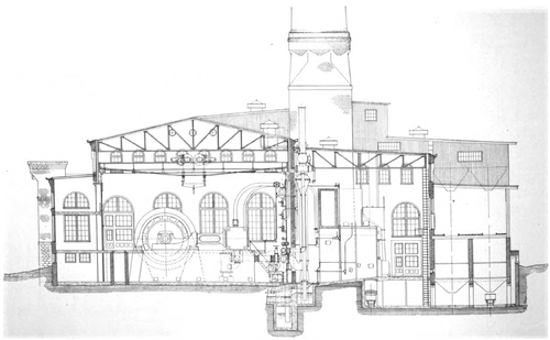 |
| Cross Section of Power House, Batavia. |
A track in the basement under the boilers permits the small cars to be loaded with ashes, and they are then run to the elevators and lifted to the level of the bottom chords of the roof trusses and run out to ash hoppers, located above the coal tracks. From these hoppers ashes may be dumped directly into freight cars and hauled away.
The exterior of the coal storage shelter is of steel, lattice at the top, and sliding doors in the middle.
The boiler room is designed for 10 boilers of 500 horse power, nominal rating; of these five have been placed in operation and three more are in course of erection. These are all water tube boilers with 4,500 sq. ft. of heating surface and 500 sq. ft. of superheating surface each, and were built by the Edge Moor Iron Co., Edge Moor, Del. A novel feature of these boilers is the front, which on each consists of a single Kinnear rolling steel door; this arrangement of front is particularly desirable in this station where the chutes from the coal bunkers above the boilers would seriously interfere with the opening of doors of the ordinary type.
Each boiler has 234 tubes 4 in. by 17 ft. 4 in., the headers being 18 ft. 10 in. between centers as measured along the center lines of the drums of which there are three, each of 30 in. diameter.
 |
| Section Showing Arrangement of Boiler Unit Mckenzie Furnace Edge Moor Boiler Green Economizer. |
Each boiler has a McKenzie traveling grate with effective area 11 ft. 8 in. long by 11 ft. wide. The arch over the front end of the furnace is of special bricks with longitudinal grooves on the sides which fit to bars of bulb section bolted to a cast iron box girder shown in end view in the line drawing of the boilers.
Each boiler is equipped with a Green fuel economizer, which is located im-mediately above the center of the boiler. This arrangement, which is different from that in any other installation made by the Green Fuel Economizer Co., makes the economizer practically apart of the boiler, as the gases pass directly into the economizer and on leaving enter the smoke flue. Each economizer is fitted with an automatic scraper which is driven by an electric motor. Each economizer has 2,600 sq. ft. of heating surface, and a water capacity of 20,000 lb.
All the boilers are fitted with Morris patented blow-off valves arranged for use as a combined wash-out and emergency valve. A feature of this valve is the making of the body and cap joints with flanged, tongued, and grooved joints, held together by two swivel eye-bolts made fast to the body of the valve; this arrangement permits the cap and stem to be easily removed when cleaning out the boilers or re-seating the valve.
 |
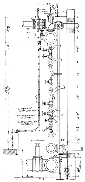
| Front Elevation of Piping on Partition Wall. |
The entire station has its foundation on rock and for the stack foundation it was only necessary to put in concrete footings extending to a depth below the lowest level of excavating necessary for waterways. This footing is about 15 feet deep. In section the stack is square up to a few feet above the roof of the station, above which point it is circular. The square portion is of stone and the rest brick. The bottom is 23 1/2 ft. square outside with walls 36 in. thick; at the top the outer diameter is 13 ft. 2 in. and the internal diameter 11 ft. The inner wall is of brick, 12 ft. internal diameter at the smoke flue entrance and 11 ft. above that point. At the base the inner wall is 17 in. thick and at the top 4 in.; it extends for 156 1/2 ft., and for the first 72 ft. the inner course, 4 in. thick, is of fire brick. The flue openings are oval 5 ft. 6 in. x 12 ft. 6 in. inside. The heighth of the stack above the grates is 222 ft.
| |||
| Pump Well. |
Back of the boilers are two 30-in. Worthington elevated condensers, one in each end of the station. Condensing water flows from the river in concrete lined conduits which extend through the station as shown in the sectional view.
The pumps are placed in a light well extending the entire length of the engine room and are all in full view from the engine room floor. The pumps which will ultimately be installed include the following apparatus, which is arranged symmetrically. Starting at the stack and proceeding in either direction there will be:
One 18 x 18-in. Worthington dry vacuum pump direct driven by a 15-h. p. motor.
One 8 x 10 in. Worthington triplex feed pump driven direct by a 35-h. p. motor.
One 10 x 6 x 10 in. Worthington duplex steam pump.
Two 19 x 15 in. Worthington triplex circulating pumps each direct connected to a 35-h. p. motor.
This arrangement gives one electric driven circulating pump foreach of the four large generating units, two electric and two steam driven feed pumps, and two dry vacuum pumps.
All the pump motors are designed for 125-volt current and were made by the Akron Electrical Manufacturing Co. , of Akron, O.
 |
| Section of Piping. |
The station was designed for four main generating units, two of which are in operation and the third in process of erection. Each of these units comprises a horizontal cross-compound engine of the corliss type direct connected to a 1,500-kw. General Electric generator. The engines which were built by the C. & G. Cooper Co. ,of Mt. Vernon, O., are necessarily massive in design, but they are at the same time very symmetrical and graceful in outline. The cylinders are 32 and 64 by 60 in., and the engine has a normal rating of 2,200 h. p. running 75 revolutions per minute under 150 lb. initial steam pressure, with 50 per cent overload capacity. The shaft is of hammered wrought iron and is 27 in. in diameter between the bearings which are 23 in. in diameter by 46 in. long, and water jacketed. The admission and exhaust valves of both cylinders are actuated by separate sets of eccentrics and wrist plates, giving independent action to the valves and a wide range of cut-off. The cut-off in both high and low pressure cylinders is controlled by a single governor of the fly-ball type, and close speed regulation and proper operation of the alternators in parallel are guaranteed. A second or supplementary governor is placed on the high pressure side of each engine to operate a quick closing valve in the main steam pipe should the speed for any reason increase 8 or 10 r. p. m. above normal. A feature which gives a very neat appearance to the engines is the heavy base plate extending over the entire width of the engine foundations under the guide barrels and cylinders, including the dash pots. These plates join with the extended webs at the base of the main bed plates, and are provided with oil channels and heavy beaded edges which unite conveniently with the floor of the engine room. The fly wheels are 22 ft. in diameter, of the segment or built-up type, and weigh 160,000 lb. each.
| |||
| Boilers From Above. |
The generators of the main units are General Electric three-phase alternators, type A-T-8 rated at 1,500 kw., the rated output of each phase being 377 amperes at 2,300 volts, when running at 75 r. p. m.
For supplying current to the motors driving the auxiliary apparatus there are two engine driven motor units each consisting of a 14 1/2 x 15 in. simple engine direct connected to an 8-pole 125-volt 160-kw. generator, and a motor-generator set comprising a 300-kw. induction motor and a 125-volt 300-kw. generator. These engines were built by the Phoenix Iron Works Co., of Meadville, Pa.; the generators are all General Electric.
The station design contemplates three 500-kw. rotary converters, which will make a sub-station equipment in the main plant.
The engine room is served by a 50-ton crane built by Alfred Box & Co., of Philadelphia. This crane has two hoists of 25-ton capacity each, which for large weights are hooked to the extremities of a yoke and thus enabled to work together. From the power station plan it will be remarked that a track some 45 ft. long has been laid into the building so that loaded cars may be run in where the crane can be used for handling heavy weights.
 |
| Detail of Pipe Brackets. |
The transformers, line switches and blowers are arranged symmetrically along the outside side wall of the generator room, the switchboard being placed in a gallery overhead. The piping for the plant is, so far as possible, all placed on the engine room side of the wall separating the boiler and engine room. Supported on suitable brackets which are furnished with rollers capable of adjusting the position of the pipe vertically and laterally, are eight mains arranged in the following order from top to bottom:
20-in. steam header, with 14-in. valve.
5-in. boiler feed main.
4-in. general water main.
5-in. dry vacuum main.
2 1/2-in. service water main.
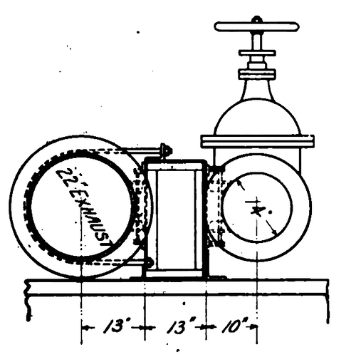
7-in. exhaust main.
14-in. condenser water main.
22-in. exhaust vacuum main .
The arrangement and connection of these headers are shown in the front elevation of the piping and by the section, which also shows the pipe leads and traveling ladder by which access to the piping is had. Each main is divided into two sections by a valve placed near the center of its length, and each section of the 16 sections thus formed is piped to a gage on the centrally located board. The front elevation shows eight of these gages, the other eight being on the left of the center line. The piping contract was let to the Crane Co., Chicago.
The station apparatus is supplied with oil by a Siegrist lubricating system, the pumps for which are located on the engine room floor opposite the stack, and the storage tanks in a room in the corner of the basement. In the oil room are two engine oil tanks, 3 ft. in diameter by 8 ft. long, and four cylinder-oil tanks, 2 ft. in diameter by 8 ft. long, two for high pressure and two for low pressure cylinder oil. Over these tanks is a wooden trough wide enough to receive two rows of oil barrels which are rolled into position, tapped and the tanks filled through funnels.
| |||
| Exterior of Power Station. |
Connections from the house water tank are piped to the bottom of the oil reservoirs and the piping and valves are so that either one of the tanks for each kind of oil can always be in service. To provide against loss of pressure on the oiling system by reason of the temporary demands on the service system an air reservoir is provided in the oil room in which air is compressed to the service main pressure, and in case the latter is temporarily reduced check valves close and the reservoir comes into action and supplies pressure for distributing the oil.
After use the engine oil is passed through Burt "Cross" oil filters and returned to the tank.
| |||
| General View of Piping in Main Station. |
In the centers of the heads of the oil tanks (which are horizontal) Mr. Morris has arranged an ingenious device for indicating the water level in the tanks without using the gage glasses, which are liable to become broken, with a resulting "muss" in the oil room. Through the blank flange closing the hand hole in the end of the tank is placed a shaft having a suitable handle on the outer end and a section of small pipe on the inner end, placed radially; a hole is bored through this shaft and the outer end closed by a pointed screw which acts as a valve, and when opened established communication between the pipe mentioned and a passage in the lower side of the flanged joint through which oil or water appears, according to the position of the free end of the radial pipe. A graduated scale indicates the amount of oil in the tank when the pipe has been rotated from a down-hanging position upwards until oil instead of water appears at the opening.
| |||
| Boiler Room From Floor. |
In this station there are an exceptionally large number of ingenious devices and interesting details, a number of which are shown in the accompanying drawings.
The water supply for the station is taken from the Fox River through a small gate house situated on the river bank. An elevation, a plan and section of this house are shown in one of the illustrations. The lower part of the house which is built of concrete contains three chambers separated from each other by means of concrete walls. The water enters the two front chambers by means of two circular gates near the lower part consisting of cast iron pipes with a lug at the bottom for fastening on the cover when it is desired to shut off the water.
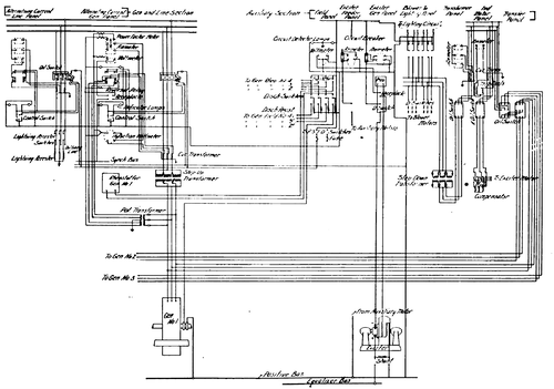 |
| Wiring Diagram, Main Power Station, Aurora, Elgin & Chicago Ry. |
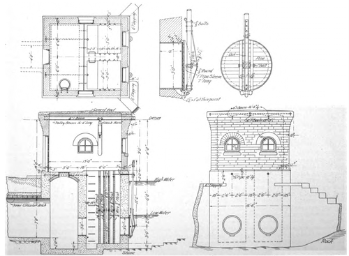 |
| Screen House at River End of Condensing Water Tunnel. |
On entering these chambers the water passes through four screens with meshes of 3/4 in., 5/8 in., 1/2 in. and 3/8 in. successively. It then passes through two gates in the partition wall of the same style as on the outside wall and which are located in direct line with the former.
From the second chamber water is carried to the water way under the pumps by means of concrete lined semi-circular arches 7 ft. in height. When it is desired to clean out the screen chambers the water may be shut off by means of covers shown in detail in the illustration. These covers are made of pine wood and are circular in shape to fit the gate casting in the concrete walls. Between the casting and the wooden cover is a ring of rubber of 1 sq. in. section which presses against the seat of the casting so as to exclude any water from passing.
| |||
| Exterior View of Power House Showing Coal Storage. |
Two parallel vertical ribs of oak extend across the cover between which the handle for fastening the cover is hinged at the center of the cover by means of a bolt running through the ribs. On the lower end of this handle is a horn which fits into the lug at the bottom of the gate casting. This handle is long enough to extend above the high water mark of the river and its upper end is fastened by a strap set in the face of the building. By drawing There up this handle to the face of the building by means of the strap the cover is forced tightly against the face of the gate casting, excluding all water.
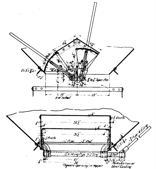 |
| Detail of Hopper Valve in Coal Storage Bins. |
By covering the outside and inside gate of either screen chamber the latter may be pumped out and the screens cleaned or repaired. In the upper portion of the building two horizontal I-beams are suspended over the center of each screen chamber on which a carriage travels carrying a block and fall. By means of the latter the screens may be removed or replaced in position.
Transmission Lines.
There are six sub-stations located as shown on the map. The high tension feeders are there indicated by broken lines, and it will be noted that there are two lines leaving the main station at Batavia, one following the railway to Sub-station No. 2 at Warrenville and thence to No. 3 at Lombard, and the other running across country to No. 5 and thence to Lombard. These two lines are of aluminum cables of carrying capacity equivalent to No. 00 copper wires. From the main station at Batavia to Sub-station No. 1 at Aurora, from No. 5 to No. 6, and from No. 3 to No. 4, other high tension feeder lines are indicated; these are of aluminum cables, equivalent to No. 2 copper.
| |||
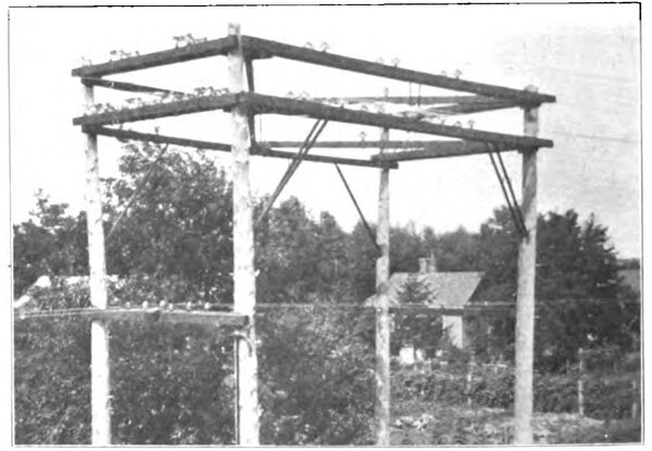
| Strain Tower at Sub-Station. |
The high potential lines are carried on 40 ft. poles with 7 in. tops, which are placed 80 ft. apart. The cross arms are 4 1/2 x 5 1/2 in. in section spaced 24 in. between centers vertically, the upper arm designed to carry two insulators, 60 in. between centers, and the lower arm to carry four insulators, 60 in. between centers, thus providing for duplicating the present feeder system when the demand for it shall arise. The insulators are the Locke No. 117, side and top groove triple petticoat, 7 in. in diameter and 4 1/2 in. high, of glass, made by Fred M. Locke, Victor, N. Y.; these are designed for a working pressure of 30,000 volts. The high tension wires are transposed every mile.
 |
| Guard Frame. |
Telephone wires are carried on cross arms about 7 ft. lower on the poles; these wires are transposed at every fourth pole. There are two complete telephone circuits, one intended for the use of the train dispatcher and one for the general business of the company; but the dispatcher may interchange the systems. Telephone booths are placed at all switches and crossovers and, of course, in the sub-stations. At intervals of about 1,000 ft . wires are brought down the poles for connecting to telephones carried in the cars. A complete bridging telephone system was furnished by the Garl Electric Co., Akron, O.
All the poles are numbered, figures about 2 1/2 in. high being used. Numbers alone are used between Chicago and Wheaton; on the Wheaton-Aurora branch the letter "A" is used in addition, and similarly "E" on the Elgin branch, "B" on the Batavia branch and "Y" on the cross-country transmission line.
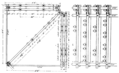 |
| Plan and Elevation of Top of Strain Tower. |
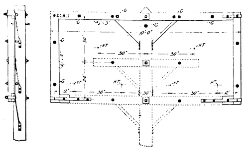
One of the line drawings shows the standard guard frame for high-tension lines, and in the front elevation the cross-arms and braces for the high tension feeders are shown dotted, the centers of the three-phase wires being also indicated by the letters H T. The top of the guard frame is formed by a cross arm 4 1/2 x 5 in. x 10 ft. and bolted and braced to the top of the pole; side pieces of same section are gained and bolted to the top piece and to 12-in. lengths of the same section at the bottom. These blocks are in line with the lower cross arm to which they are spliced by 1 3/4 x 1/4-in. iron U-straps. Adjacent poles carrying guard frames are connected by eight 7-strand galvanized steel cables which are fastened to eye-bolts of 3/8-in. round iron located at the points marked G in the drawing, and a ninth which is fastened to an eye-bolt through the pole. The guard wires are 21 in. between centers. The drawing also serves to show the cross-arm braces which it will be noted are twisted near the bottom and fastened to the side of the pole with two lag screws instead of being fixed to the front with but one screw or bolt.
Wherever the Aurora, Elgin & Chicago feeder lines pass under telegraph or telephone wires, guard frames are placed on the poles of the railway line and guard wires stretched. The guard wires are placed sufficiently close together so that it is not expected that a wire falling upon them can reach the high-potential circuits; but all the guard wires are grounded so that in case of such an accident the worst that can happen is the grounding of the railway circuit.
This construction is contrary to the usual practice, but the railway company believes that the use of a strongly built guard and passing underneath other circuits is preferable to introducing a weak place in the line by using taller poles and carrying its wires above the wire lines it has to cross.
Sub-Stations.
The six sub-stations are located so that they form convenient centers of distribution. The continuous current produced at the sub-stations is fed directly into the third rails so that all direct current feeders are done away with. Outside of the sub-stations the only cables used are for connecting the ends of the third rail at streets and grade crossings with other railroads. The sub-stations are numbered from one to six and are located as follows: No. 1, at Aurora; No. 2, Warrenville; No. 3, Lombard; No. 4,Maywood; No. 5, Engleton; No. 6, Clintonville.
| |||
| Lombard Sub-Station \"Climax\" Cattleguard and Conductor Rail Terminals in Foreground. |
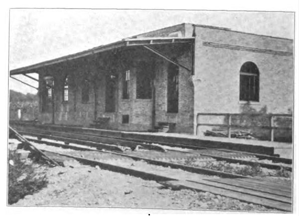
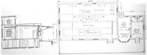
The electrical equipment of all the sub-stations is practically identical, but the buildings are constructed according to two different plans, one plan showing a dispatcher's office, waiting room and platform for passengers, while the other is without these rooms, and contains only the rooms necessary for the electrical equipment. The accompanying illustration shows the general arrangement of the larger sub-stations which are used for passenger stations, and the construction is entirely of brick and stone, making the buildings as absolutely fireproof as is possible. The sub-stations built after this plan are those at Warrenville, Lombard and Maywood; the other three stations are practically the same with the passenger accommodations omitted . The section in which the machinery is contained is 57 x 36 ft. and consists of a main room, a basement and a loft 12 x 33 ft. into which the high tension overhead lines are brought.
 |
| Wiring Diagram of Sub-Station. |
In front of each sub-station is a strain structure for taking the strain of the overhead wires before they pass into the sub-station loft. The accompanying illustration shows a working drawing of this structure. Instead of depending upon a single insulator for taking the stress in the direction of the line the insulators are arranged in sets of four. The line cable passes between these and is tied to a yoke made of 5/8-in. iron with the ends slightly bent and tied to the second pair of insulators by two ties of wire which are twisted until it is apparent that the load is distributed between the two pairs of insulators.
 |
| Plan and Section of Sub-Station With Waiting Rooms. |
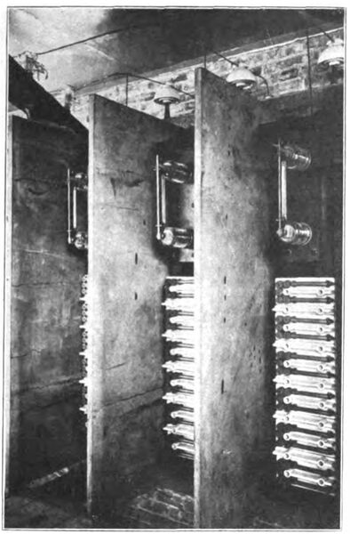
From the strain structure the wires pass into the station loft through special insulating tile and immediately after entering the building are connected to G. E. lightning arresters. The three wires of each circuit after entering the building each connect to large oil switches making two breaks in each circuit, and thence run down to the high tension bus-bars in the basement, which are very ingeniously encased in brick conduits which afford almost perfect insulation yet leave all of the wires entirely exposed for inspection. The compartment in the basement which contains these high tension bus bars has iron doors which close hermetically in order to permit a circulation of air under pressure through this chamber. The high tension "bus bars" consist of No. 2 stretched in a brick and concrete structure erected in the air lock under the transformers, the arrangement being practically the same in the central and the sub-stations. The bus for each branch of the circuit is located in a tunnel made by placing horizontal partitions of cement concrete between vertical side walls of brick; and the leads to the oil switches and transformers are similarly separated by 4-in. vertical brick walls supported by steel angles at the corners.
| |||
| High Tension Lightning Arresters. |
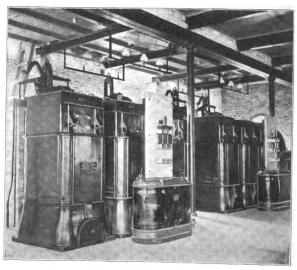
It is noticeable that all the sub-station wiring is arranged so that all the wires and cables except those pertaining to the instruments on the switchboard are carried in the basement, and there are no high tension wires or heavy cables to be found in the main room where the machinery is located. This main room contains two General Electric rotary converters type H. C. running at 1,500 r. p. m. These transform alternating current of 25 cycles at 430 volts to constant current at 600 volts. There are six transformers of the A. B. type wound for a primary voltage of 26,400 and a secondary voltage of 430; two reactive coils, type R. C. 48; two Buffalo Forge Co. blowers each driven by a 3 h. p. General Electric induction motor, type 1, for furnishing the air for cooling the trans-formers and the high tension bus compartment in the basement.
| |||
| Rotaries in Sub-Station. |
The accompanying reproductions from photographs of one of the sub-stations shows the relative location of the machinery and the switch board. The latter is arranged in three general divisions which are alternating current high tension line panels, the direct current rotary converter panels and the direct current feeder panels. In the Lombard station from which the illustration is taken are three alternating current line panels for one outgoing and two incoming circuits. These three panels are at the left hand end of the board and the next two panels are used for the alternating current side of the rotary converters.
| |||
| Sub-Station Switchboard. |
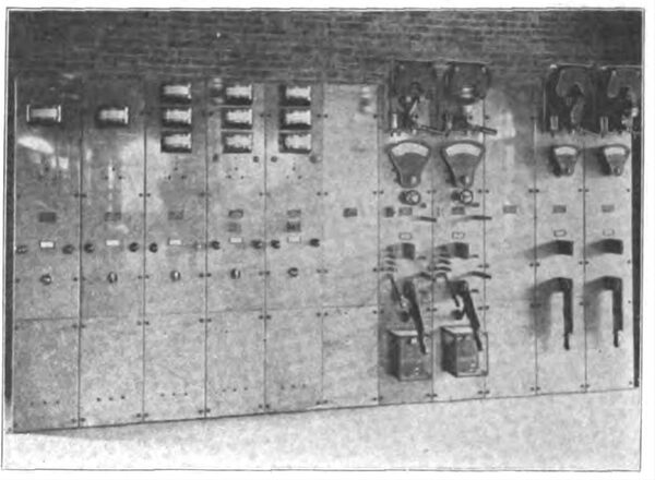
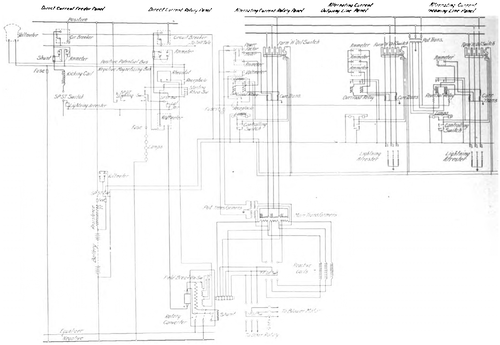
The diagram of wiring shown herewith will serve to explain the switchboard arrangements of all the sub-stations. The incoming line panels each contain one Thompson ammeter, one reversible relay, two signal lamps and a controlling switch for throwing the oil switch which opens and closes the circuit. The oil switch is provided with a motor which operates automatically as soon as the switch has been thrown and which keeps it constantly in readiness to be operated by a tripping device which is controlled by a small auxiliary switch at the switchboard. The two lamps above these controlling switches show whether the oil switch is open or closed, one position being indicated by a red lamp and the other by a green lamp. In case the incoming current should tend to reverse the sub-station machinery on account of its higher potential the reversal relay shown in the diagram comes into action. By means of a solenoid it can be adjusted to any required reading. The oil switch is operated if this reading is exceeded, in a similar manner as by the controlling switch. The panel for the outgoing current is similar to the one just described except that it contains an ammeter for each phase of the circuit and in this case a simple overload relay is used in place of the reversal relay on the incoming line. These relays are connected in parallel with the controlling switch and signal lamps, and are operated by means of the solenoid the core of which in rising closes the controlling switch circuit. The panels for the alternating current side of the rotary converter each contain a power factor meter, an ammeter and a voltmeter, two synchronizing lamps, a plug receptacle for throwing the instruments in circuit, the controlling switch and signal lamps for operating the oil switch. On the back of the panel is an overload relay for operating the oil switch as previously described. The two panels controlling the direct current side of the rotary converter are separated by the width of one panel from the alternating current panels already described. These panels each contain a circuit breaker, an ammeter, a rheostat, a starting switch, lightning arrester and wattmeter. As the relays and controlling switches for operating the oil switches require continuous current a storage battery is provided for use in starting the plant when the rotaries are not in operation and there is, therefore, no continuous current available. The line current of 600 volts is cut down to a pressure of 125 volts by means of a resistance inserted in series and this pressure of 125 volts is used both to operate the relays and controlling switches and to charge the batteries when required.
| |||
| Oil Switches and Transformers. |
The two panels to the extreme right of the board are for the direct current feed to the third rail. These each contain a circuit breaker, ammeter, voltmeter, kicking coil and a lightning arrester. A connection is made in the winding of the transformers so that the rotary converters can be run up to speed as motors with only a portion of the normal pressure. When they reach full speed this intermediate voltage is cut off by means of a double throw switch and the normal pressure is supplied.
Rolling Stock.
The rolling stock of the Aurora, Elgin & Chicago consists at present of 30 cars of the style shown in the accompanying engraving. Twenty of these cars are equipped with motors and the remaining ten are used as trail cars. The car bodies were made by the Niles Car & Manufacturing Co., of Niles, O., and as will be seen from the illustration are very handsome in general appearance. The construction of the framing is novel and was designed for the special purpose of withstanding the exceptionally high speeds to which the cars will be subjected. The length of the bodies over end plates is 47 ft. 3 in. and the extreme width of the cars over the side sills is 8 ft. 6 in. The cars are vestibuled and furnished with non-telescoping ends. The under framing is entirely of 5-in. and 6-in. steel I-beams riveted together wtih [sic] with special channels and plates. The lines of the car body are similar in general appearance to what has come to be known as the Pullman style of sleeping car with compound Gothic windows. The Gothic sash is set in art glass, which adds greatly to the general appearance of the car. The interior of the roof presents a rich appearance and is ornamented with stripes and studded with frosted incandescent lamps, each of 16 c. p. set in sockets of oxidized copper. The ventilating sash are eliptical [sic] elliptical with art glass set in three sections. The ceiling is painted blue and the interior is rubbed down to a dead finish, the latter being in quarter oak and decorated with marquetry work.
| |||
| Standard Car Niles Car & Manufacturing Co. |
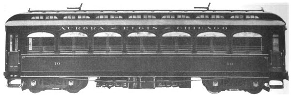
The trimmings are of solid bronze. The seats are of the Hale & Kilburn walk-over pattern made of rattan and furnished with high backs and roll top head rests. Under each seat is supplied a Consolidated car heater. The car is arranged with cross seats and a center aisle, the latter being laid with matting . Each car has a smoking compartment and the trimmings throughout are of polished bronze. On each side are continuous basket racks and the glass is polished plate throughout.
 |
| Arrangement of Contact Shoe. |
Each car is equipped with four of the Nichols-Lintern Co's. pneumatic sanders; these enable sand to be as efficiently distributed on curves as on straight track, insuring uniform track conditions when stopping, and preventing slipping of wheels at starting. The other special equipment includes Van Dorn draw bars and couplers, Stanwood double steel steps , foot gongs, push buttons at each window, two trolley poles, rear and front signal lights, rear flags, fire extinguishers and a full line of tools in tool boxes to be used in case of accident. The vestibules have side doors and the step openings are provided with trap doors. The ends of the vestibules are open to allow passage from one car to another when run as a train. These cars are to be put under a speed test by the General Electric Co. and it is the intention to obtain speeds as much in excess of100 miles an hour as possible.
In order to accomplish these tests the cars will be supplied with different types of portable vestibules to overcome the air pressure at high speeds.
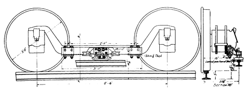
The bodies are mounted on Peckham M. C. B. No. 30 trucks with 62 -in. axles and 36-in. M. C. B. standard double plate cast iron wheels. The journals are 5 x 10 in. A side elevator of the truck and a transverse section through the center of the bolster are shown in the line drawings. These trucks were designed especially for high speed interurban service.
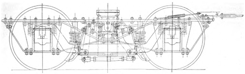 |
| Side Elevation of Peckham M. C. B. 30 Truck. |
The side frames combine the equalizing bars used in the Master Car Builders' steam passenger car trucks with the diamond frame used in the M. C. B. freight car trucks, the idea of the combination being to give a double factor of safety, as the diamond frame alone is sufficiently strong to carry the weight of the car without the aid of the equalizing bars, which are arranged in pairs, one each side of the pedestals. To prevent the tilting of the top frames the spring base of the truck is increased by locating helical springs each side of the journal boxes and supported from them by saddles. These pedestal springs carry a sufficient portion of the load to prevent the tilting of the top frames, the greater part of the load being carried by the equalizing bar springs. The side and end portions of the top frame are all in one piece, a forging. The transoms are bulb angles 10 in. deep, which extend full size with the side truss frame to which they are very rigidly secured. Gussets of sheet steel connect the transoms to the side frames hold the frames rigid and square. The trucks have Peckham's patent swing bolster; this is constructed of plates in form of a channel 10 in. deep and is carried on four long coil springs and one elliptic spring which support the bolster from the inside at its top, so as to hold it securely in a vertical position. Straps secured to the transom and extending over the bolsters prevent its being lifted out.
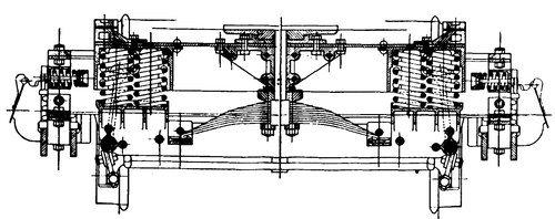 |
| Transverse Section Through Bolster. |
The arrangement of bolster springs, an elliptic in the center and two helical springs at each end, is designed to give an easy riding car and to prevent rolling motion of cars when running at high speed.
Each motor car is equipped with four G. E. 66 motors, 125 h. p. each, making a total of 500 h. p. per car.
These cars are supplied with the Christensen straight air brake equipment with independent motor driven compressors and automatic governors. The compressor and motor are combined in one machine consisting of a series wound motor and a duplex single-acting compressor. The motor is mounted directly above the compressor, the motor base forming the top cover for above the compressor, the motor base forming the top cover for the same, and this arrangement enables all the working parts to be run in oil. The governor used for this compressor consists of an ordinary Bourdon pressure gage mechansim [sic] mechanism with a special hand which makes contacts with the conducting stud at the position of minimum pressure and allows current to flow through a magnetic coil which operates a plunger carrying contact pieces for the motor circuit whereby the motor is started up. When the hand strikes the maximum stud the current is reversed and the plunger pulled away so as to break the circuit and stop the motor.
The cars are operated with the General Electric type M control system, which is adapted for running the cars separate or when two or more are coupled together in a train. When the cars are operated in a train the circuit connections are so arranged that the motors on all of the cars may be controlled from either end of any motor car. The type M system consists of two essential parts, namely, a series parallel motor controller composed of a number of electrically operated switches called the contactors and a separate electrically operated reversing switch called the reverser, and second, two master controllers, one located at each end of each motor car, which operate the contactors and reversers. A cable running the entire length of the train connects each master con-troller with the controlling circuits of the several motor cars and these cables are connected from car to car by means of suitable couplers. It is also necessary to continue these cables through any trail cars which may be in the train between the motor cars.
