[Trade Journal]
Publication: Street Railway Journal
New York, NY, United States
vol. 20, p. 564-577, col. 1-2
THE AURORA, ELGIN & CHICAGO RAILWAY
WHILE it is not always easy for those in the midst of events to judge of their relative importance, it is probably not far from a correct estimate to say that future historians of electric railway progress will note the construction of the Aurora, Elgin & Chicago Railway as one of the important mile-posts in the history of the electric railway. Many people have asked the writer what is the notable feature of this road which is attracting so much attention to it. The answer in a nutshell is speed. That is the one characteristic which to the lay mind distinguishes the road from dozens of other electric railways. The detailed discussion of all the elements which go to make possible in a financial and engineering way this one element of speed, forms the principal object of this article.
There are two standpoints from which to consider the work on the Aurora, Elgin & Chicago Railway, that of the electric railway financier and that of the electric railway engineer. The financier sees in it a road which is expensively, though not extravagantly, built, and which has liabilities in the shape of stocks and bonds per mile of track about double the ordinary interurban road. To show for this investment he sees a road built after the manner of the heaviest steam-trunk lines, equipped with electrical apparatus and rolling stock to carry people between Chicago and three towns 40 miles west in the Fox River Valley at a speed and with a frequency to completely eclipse any service heretofore given by the steam roads between those points. He sees further preparations to carry people to intermediate and suburban points at a speed and frequency, having no previous parallel in railway history. The engineer sees a third-rail electric road with alternating-current power distribution. He sees a track, over much of which 80 miles to 100 miles an hour can be made with safety. He sees cars equipped with the multiple-unit system of control, with the heaviest motor equipment ever put under an electric car for its own propulsion alone; in fact, with all provisions made for a regular maximum speed of 65 miles per hour and an acceleration at the rate of 2 miles per hour per second to attain it, a performance never before equaled in regular electric railway practice. Certainly these are matters worthy of closer investigation by both financier and manager, for they mean much to the future of the electric railway industry.
The road owes its financing and construction to a number of Cleveland gentlemen, who are by no means novices in the electric interurban railway business. L. J. Wolf, of Cleveland, is president; M. H. Wilson, vice-president; M. J. Mandelbaum, treasurer, and Warren Bicknell, of Chicago, secretary. During the construction of the road Will Christy, of Akron, Ohio, has acted as general manager, and W. E. Davis, of Cleveland, as electrical engineer. These gentlemen of the Cleveland Construction Company and their associates deserve much credit for the splendid piece of engineering afforded by the road. The other gentlemen actively connected with the construction were Charles Jones, chief engineer, who has been on the ground in charge of the construction of the road from the beginning; W. L. Morris, mechanical engineer, who designed and built the power station, and Ernest Gonzenbach, electrical engineer in active charge of electrical construction. In operation, the road is under the general supervision of Secretary Warren Bicknell, with C. E. Flenner as auditor; W. W. Crawford, superintendent of transportation; Ernest Gonzenbach, electrical and mechanical engineer in charge of power house, electric power distribution, shops and maintenance of rolling stock, and Charles Jones, engineer maintenance of way and structures.
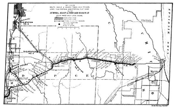
To build the 82 miles of track which the company will have when the road is completed, a bond issue of $3,000,000 and capital stock to the amount of $4,500,000 is provided for. Of the $4,500,000 stock $1,500,000 is 6 per cent cumulative preferred. The bonds bear 5 per cent. The bond issue is therefore $36,585 per mile, and the total liabilities $91,219 per mile. As this is considerably higher than on most interurban roads up to the present time, it is natural to inquire into the conditions which have justified this expenditure in the minds of the builders of the road. That the conditions were unusual goes without saying. For a distance of 20 miles due west from the Chicago city limits is a series of suburban towns with an aggregate population according to the 1900 census of 24,065. Thirty-five miles west of Chicago is a belt of towns along the Fox River which are already interconnected by the Elgin, Aurora & Southern Traction Company lines, but which have had only infrequent steam service to Chicago. The new road, as seen by the accompanying map, touches the Fox River Valley at the three largest towns; Aurora, with a population of 21,147; Batavia, 3871, and Elgin, 22,433. The total population reached directly in the Fox River Valley by the Aurora, Elgin & Chicago Railway is 47,451, and that in the towns along the valley reached by the Elgin, Aurora & Southern Traction Company lines, which population is really tributary to the new road, is 91,224. Taking all the population in the tributary Fox River towns, together with the suburban population mentioned, gives a total of 115,289 tributary to the road, not including rural population. This is 1405 per mile of track. Now it can be seen why such an expenditure was justified. The population per mile along many good electric interurban lines running into less important centers than Chicago is frequently less than 500.
In order to make this undertaking fully successful, those responsible for it rightly figured that if the maximum possible business was to be developed fast schedules must be made. It would undoubtedly have been possible after many years of vexation to secure a franchise along the highways and to operate at the usual schedule of 15 miles to 20 miles per hour, picking up considerable local travel, as many another road has done before. But the men to whom time was valuable would have planned their trips as far as possible for the suburban steam trains, and many a person would have remained at home, where fast service at frequent intervals would have induced them to ride. It was decided, therefore, since there was population to justify it, that track and roadbed should be built on a private right of way, and of such substantial construction that over the greater portion of the route there would be nothing to hinder sustained runs at speeds as high as known to the railroad world of to-day. It was further decided to provide electrical equipment which would give the fastest schedules possible (with stops 3 miles apart on local service 40 miles per hour), 65 miles per hour maximum speed. Only the electric railway engineer familiar with schedule speeds and rates of acceleration in common use can realize what a bold step in advance of previous actual commercial practice this was. To accelerate a car from a stand-still up to a rate of 50 miles per hour in 25 seconds to 30 seconds, and to sustain it at a speed of 65 miles per hour, calls for an investment in motors and power furnishing apparatus that is apt to make the engineer and manager hesitate when it comes to the actual selection of the equipment. But the step was taken, and the result is the most powerfully equipped and solidly constructed interurban electric railway in existence to-day.
 |
| Map Showing Route of Aurora, Elgin & Chicago Railway |
The fast acceleration needed for the local service making all stops as well as the long runs at high speed practically threw out of consideration everything but the multiple-unit system. The equipment of the motor cars is four 125-hp G. E.-66 motors. The General Electric Company's type M train-control system with small master controller on each platform operating magnetic contact makers or "contactors" under each motor car was adopted. One and two-car trains will have every axle motor driven. Three-car trains will have one car without motors. The motorcars have the most powerful equipment ever put on a motor car, except on elevated roads, where the motor car acts as a locomotive to pull trailers. The type-M control permits the train or car to be operated from any car, and is practically the same as that put on the Manhattan Elevated in New York, and was described, together with the G. E.-66 motor here used, in the October (1901) STREET RAILWAYJOURNAL.
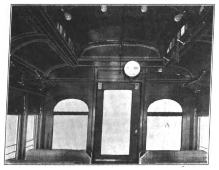
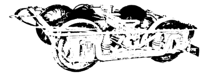
The cars upon which these motors are placed were built by the Niles Car & Manufacturing Company, and are notable for strength of sub-frame, drawings of which are shown. These cars are 47 ft. over bumpers and 39 ft. 4 ins. over bodies. This length was selected to allow the cars to pass around the sharp curves of the Union loop in Chicago as it was the original intention to run these cars into Chicago over the tracks of the Metropolitan West Side Elevated Railway. The cars seat fifty-six people in seats disposed according to the seating plan shown. There is no waste room either on platforms or inside the car, hence the relatively high seating capacity as compared with other interurban cars of similar length. The heating is by Consolidated electric heaters placed along the side of the car. An exterior view of one of these cars is shown in the article elsewhere in this issue on "Cars for High-Speed Interurban Service." An interior view of one of these cars is given in this article and shows the location of the International register on the partition between the smoking and main compartments. The seats are rattan of the Hale & Kilburn walk-over type, 38 ins. wide. Van Dorn draw-bars are used. The trucks are Peckham's M.C.B. 30, which follows the general lines of a M.C.B. truck, but has a diamond frame and combines spiral and elliptic springs under the bolsters. In addition to the regular equalizer springs which support the frame, there are spiral springs between the frame and each journal box, which take a small part of the weight and are intended to prevent the tilting of the frame. Nichols-Lintern compressed air track sanders are mounted on the truck frames so that they will sand the track both on curves and straight line. The Christensen straight air brakes with independent motor-driven compressor and automatic motor regulator are employed. The automatic motor regulator is controlled by electric contacts on the air-pressure gage. The car wheels are 36 ins. in diameter, and have the standard M.C.B. tread and flange. The axles are 6½ ins. in diameter, the largest yet used under an electric motor car.
The weight of these cars is 74.325 lbs. The motors alone weigh 17,120 lbs. The gear ratio is 1.61 to 1, and the large size of the pinions and car axles and smallness of the gearwheels gives a most peculiar "fat" appearance to the equipment when apart.
 |
| Standard Truck |
Although no extensive tests have been made on the performance of the regular car equipment in service because of the short time the road has been operating and the many more pressing duties claiming attention, it has been found that at full speed the current required by a car on level track is 400 amps. At present line voltage, these cars run a little under 65 miles per hour maximum on a level. When accelerating at the rate of 2 miles per hour per second with motors in multiple, they require 1200 amps. or 300 amps. per motor. The present equipment consists of ten motor cars, and ten more motors and ten trailers are ordered. It is safe to say that never before in the history of electric rail-roading have motor cars been put through the daily mileage that some of these cars were put through the first two weeks the road was in operation, when, on account of lack of cars, some cars were run over 550 miles per day.
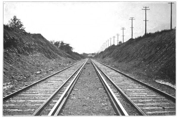
There are approximately 82 miles of main line, all on private right of way, the route of which is shown by the accompanying map. From Fifty-Second Avenue in Chicago, which is the eastern terminus, where the road connects with the Metropolitan West Side Elevated Railway, and at which point an elaborate transfer terminal depot has been erected, the line is double tracked for 21 miles to the golf grounds, 1 mile west of Wheaton. From Wheaton to Aurora is 14 miles, with a branch of 7 miles to Batavia. From Wheaton to Elgin is 16½ miles. The branches to Aurora, Batavia and Elgin are nominally single track, but have long sidings, which practically make the road double tracked for short distances, and really should be counted as short sections of road double tracked. Three miles west of Wheaton is 800 ft. of double track; 9 miles west of Wheaton is 1 mile of double track; 12 miles west of Wheaton, or about 2 miles from Aurora, is 400 ft. of double track. At Aurora there is double track for 1 miles. On the Batavia branch is 3/4 mile double track, at the main power house, and 700 ft. of double track at the Batavia terminal. On the Elgin branch there is 1/2 mile double track at Ingalton depot and sb-station [sic] sub-station, 1000 ft. at Wayne, mile near the southern city limits of Elgin and 1500 ft. in the city of Elgin at the terminal. On the single-track portion of the line when large cuts were made they were cut sufficient width to provide for a double-track line in the future as soon as it is needed. Between Wheaton and Aurora there are 21 miles of this double-track grading.
 |
| Plan and Side Elevation of Car, Showing Steel Sub-Frame |
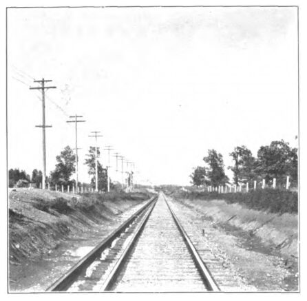
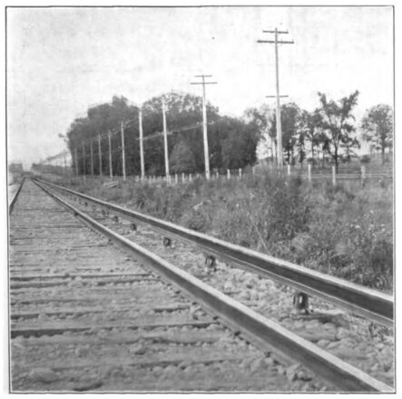
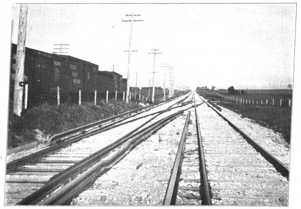
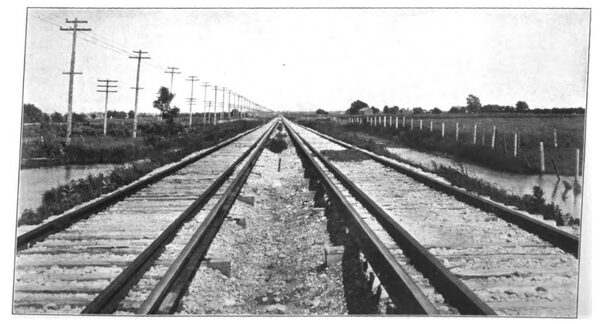
The roadbed for single track is 16 ft. wide, with 9 ins. of gravel ballast. The double-track roadbed is 28 ft. wide, which is also the width of the single-track cuts where provision is made for double track. Double tracks are laid 15ft. between centers. Current is supplied from a third rail which occupies the standard position relative to the track, which is in use on the elevated roads of Chicago and elsewhere. The top of the third rail is 6 3-16 inches above the top of the track rails, and it is placed 19 ins. outside of the nearest track rail, the gage lines of the track and third rail being used as points of measurement in this case, and not the centers.
| |||
| Interior View of Car |
The track rails are standard T, 80 lbs. to the yard, in 60-ft. lengths. They are joined with four-bolt angle-bars 28ins. long. The third rail is standard T, 100 lbs. to the yard, in 33-ft. lengths, and in order to give it better conductivity it is made of a lower percentage of carbon than the track rails, the percentage being .1. The regular ties are 6 ins. x 8ins. x 8 ft., 2840 to the mile. Every fifth tie is 9 ft. long, and carries on one end an insulating support for the third rail. Except at two points, Wheaton and Waldheim Cemetery, where there are 16-deg. curves, the curves are limited to 1 deg., 2 degs. and 3 degs., so there is nothing to require a reduction of a speed from 70 miles per hour.
| |||
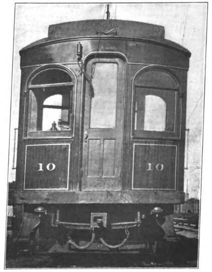
| End Door in Vestibule of Car |
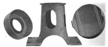
The third-rail insulators were furnished by the Ohio Brass Company. The first of these laid were wooden blocks boiled in paraffine oil, and the balance a special design of Mr. Gonzenbach, made by the same company. This new design of third-rail insulator consists of a cast-iron base, over which fits a thin circular cap of "Dirigo" insulating material. On top of this is placed the cast-iron cap, upon which rests the third rail. The insulating material is not joined to the cast-iron fittings in anyway, and the rail simply rests on top of the cap, as the weight of the rail is sufficient to hold the three parts of the insulator together.
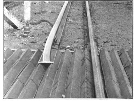
The arrangement of the third rail at the cross-overs and the cable terminals connecting the third rail with the lead-covered underground cables, are clearly shown in the accompanying engravings. It will be noted that instead of omitting the third rail at the beginning of a cross-over to prevent catching of the contact-shoes on cars which are passing along the main line, the third rail has been bent downward so as to clear the contact-shoe. This is a more simple construction and does away with some under-ground connections which would otherwise be necessary were a separate isolated section of third rail put in for the cross-over. On the double track there is a cross-over about every three miles. The switches are all of the standard steam-road pattern, with No. 10 spring frogs, furnished by the Morden Frog & Crossing Works. Interlocking signal towers, with home and distant signals so that trains need not stop if the way is clear, are placed at three points where the steam roads are crossed. One of these is at Forest Home Cemetery, where the Wisconsin Central, Great Western and the Chicago Terminal Transfer Companies' tracks are crossed. Towers are also located at Chicago Junction Railway crossing, and at the crossing with the Illinois Central, at South Elmhurst. As far as possible highways and steam roads have not been crossed at grade.
 |
| Plan of Car Showing Seating Arrangement |
At highway grade crossings it is, of course, necessary to omit a short section of the third rail. At a 66-ft. highway crossing, which is the regular width of country highways, the third rail is omitted for a distance of 75 ft. For connecting across this interruption in the third rail, a lead-covered cable of 1,500,000-circ. mils cross section is placed in the ground, no protection being used for the lead sheath except aboard placed over the cable. The Climax vitrified clay stock guards have been put in at all such crossings.
| |||
| Single Track, Good for 100 Miles An Hour |
The bonding of the track rails is accomplished with two United States bonds of the American Steel & Wire Company at each joint. These bonds are 12ins. long, with 1-in. terminals, and have each a cross-section of 250,000 circ. mils. Each third rail joint is bonded with two Protected Rail-Bond Company's bonds of 250,000 circ . mils. Tracks are cross-bonded ten times every mile with bonds of 300,000 circ. mils.
| |||
| Third Rail and Insulators |
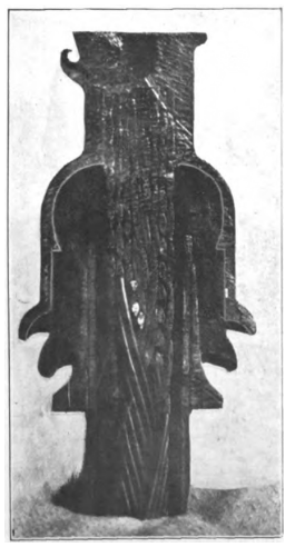
Experience has demonstrated the necessity for thorougly [sic] thoroughly protecting the ends of the conductor and sheath of the lead-covered cable which is used for connecting across the break in the third rail at highway crossings and special work. If this is not done moisture soon works in between the lead sheath of the cable and the conductor, and as the distance between these is very short, there is certain to be trouble unless there is some means of protecting the insulations from moisture at the place where it is cut. A special terminal has been designed by Mr. Gonzenbach, which has the double purpose of forming a connector and protecting the cable insulation at the end of the cable. In this terminal a bell of insulating material is clamped firmly down over the end of the lead sheath, and poured full of an insulating composition. Electrical connection is made by a cap, which is soldered over the end of the stranded cable conductor and to which a terminal lug is secured by a cap screw. This terminal lug is soldered to copper bonds connecting with the third rail.
 |
| Third Rail, Insulator Apart |
A cast-iron tip is put on the third rail where it is interrupted, which furnishes an incline for the contact-shoe of the car. These tips can be seen in the engravings. They are 28 in. long, and in addition to the incline these afford, the third rail is dropped 2 ins. in 33 ft. approaching the tip.
Bridge work has been mainly of concrete masonry, with deck girders wherever possible, and elsewhere through girders between concrete piers. This concrete masonry is in striking contrast to some of the wooden trestle work on adjacent steam roads, and simply illustrates one of the many ways in which this company has spared no expense to get the best. Some of these bridges and culverts were illustrated in the STREET RAILWAY JOURNAL of February, 1902. Power for the whole road is supplied from sub-stations operated by high-tension alternating current, from a powerhouse at Batavia on the Fox River. This power house contains many interesting features, for which William L. Morris, mechanical engineer, is responsible. Drawings showing its general arrangement were given in the STREET RAILWAY JOURNAL of February, 1902. Lack of space forbids going into a discussion of the power house until later. The present article will confine itself to the electrical distribution and matters intimately related to it.
| |||
| View Showing Arrangement of Third Rail at Cross Over |
The road is laid out for six sub-stations, the locations of which are indicated on the map. The transmission is by 26-000-volt 3-phase alternating current.
The high-tension lines are carried on cross-arms with insulators 30 ins. between centers on the cross-arms, and the cross-arms 24 ins. apart. The telephone lines are on cross-arms 7 ft. below the lower transmission cross-arm. There are two telephone circuits, one for general business and the other for despatching. The telephone lines are transposed every fourth pole, and the high-tension lines every mile, both being transposed more frequently than is common. The telephone wires are transposed by tieing both to a single wide petticoat transportation insulator every fourth pole.
No direct-current overhead feeders are needed, as the third rail has sufficient carrying capacity to conduct all the current from the sub-stations to the trains. The overhead pole line, therefore, has only to carry the 26,000-volt three-phase high-tension feeders which supply the various sub-stations and two telephone circuits. The high-tension feeders are of standard aluminum cable equivalent to No.000 copper wire. The poles carrying these lines are 40 ft.long placed 80 ft. apart, sixty-six to the mile. In towns the poles are 60 ft. long. The system of high-tension distribution is very complete, and is arranged to secure freedom from interruptions of service due to short circuits or breakages on anyone transmission line. The high-tension lines are indicated by dotted lines on the accompanying map. Three high-tension feeder lines leave the power house. From the power house to Batavia a line runs direct across country to sub-station No. 1, near Aurora. Another high-tension pole line follows the line of the railroad, supplying sub-stations Nos. 2, 3 and 4, and extending to Maywood. The third line from the lower power house is built directly across country to sub-station No. 5 on the Elgin branch, and along the right of way from this sub-station to Wheaton, at which point it joins the pole line from the Aurora branch, and the two three-phase circuits run on the same poles to sub-station No. 3, with one circuit from there to No. 4. Sub-station No. 6 is supplied by a single line running from sub-station No. 5.
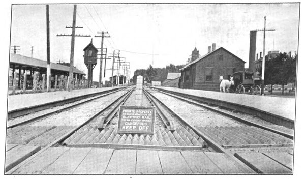
Another respect in which this transmission differs from he majority is in going under, instead of over, a number of other pole lines. The usual practice is to carry the high-tension lines over every other pole line. This line goes under all unusually high telephone pole lines, and at such places guard-wires are put over the lines. The guard-wires are strung between rectangular frames surrounding the cross-arm, some of which can be seen in the back-ground in the view taken at Wheaton.
| |||
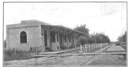
| Sub-Station and Platforms at Maywood |
At the crossings, which are of sufficient length so that the car must drift for a distance with no current, the annoyance to passengers from the lights going out will be obviated by putting up a short section of trolley wire at these places, with which a small sliding contact-bow trolley on the can roof will make contact. This will carry current enough for the lights on the car. The arrangement of the direct-current feed and sectioning of the line is a matter of much importance on a high-speed road of this kind, where the fluctuations in load will be extremely violent.
The arrangement employed on this road is practically the same as on all interurban roads fed by sub-stations. The third rail between any two sub-stations constitutes a continuous section fed from the sub-stations at each end. Sectioning of the third rail takes place only at the sub-stations. Each sub-station will, therefore, feed both ways, and as long as there is no trouble on the line, all the third-rail sections on the entire system will be connected together through the medium of the sub-station bus-bars and feeder panels, so that there will be opportunity for the sub-stations to divide the load among each other as far as the conductivity of the third rail will permit, and in case of an excessive load upon one section, the sub-station nearest will not be required to carry the total load. In case of a short circuit on any section of a third rail the circuit breakers at the two sub-stations that feed it will open, and it will be entirely disconnected. On the double track part of the road, the third rails on the two parallel tracks are not to be connected together permanently, but form two separate sections connected through the medium of the sub-station feeder panels and bus-bars, just as are any other sections.
 |
| Section Through Cable Terminal |
To the specialist in high-voltage switch-boards and switching arrangements the installation is of more than usual interest, because it is one of the first large high-tension alternating-current distribution plants to go into operation in which all the switching will be done on the high-voltage side of step-up and step-down transformers. Each generator in the power house has its own bank of three transformers, and each rotary converter in the sub-stations has its bank of three transformers. In each case the trans-formers are considered as a unit with the generator or converter. Each generator is connected with its bank of transformers directly without any switches or circuit breakers. In other words, each generator and its transformers constitute practically a 26,000-volt machine. Doing away with all low-tension switching apparatus and depending on switches in the 26,000-volt circuit alone is a proposition at first nothing short of startling to those familiar with the high-tension work that has been done in the past, and especially that in the far West, where it is the practice to do as much of the switching as possible on the low-tension circuits The manufacture of oil switches, which will with certainty open circuits of over 20,000 volts, has, however, materially changed the nature of the problem. Once a high-tension switch is introduced which is easily operated and certain in operation there are many reasons for doing way with the expense and complication of low-tension switches. The oil switch, which has made this feasible, is of the same general type as that made by the General Electric Company for the Manhattan Elevated power house in New York. Each leg of the switch is in an oil cylinder in a separate brick compartment. It is motor operated, a motor on each switch keeping wound up a spring which trips the switch open or shut. After each operation of the switch the motor winds up the spring to make up for the amount it un-wound during the operation. The motor is operated by direct current from the exciter panel, and is entirely automatic in its action. The trip of the switch is also worked by direct current from a small switch on the generator panel. Indicating lamps on the generator panel show whether the switch is open or closed.
| |||
| Third-Rail Tap and Cable Terminal |
Taking up the circuits in their logical order, on the station-wiring diagram, the main current from the generators (2300-volt three-phase) is taken directly to the low-tension terminals of its three-delta connected transformers, taps being taken off between the generator and transformer for a potential transformer which supplies switchboard instruments on the generator panel. Taps also lead off to a three-pole, double-throw oil switch on a transfer panel, from which a panel governing an induction motor driving the exciter is run, and also blower motor and lighting circuits. On the transformer panel the three generators are so connected, as seen, to the two three-pole, double-throw oil switches as to allow any of the three generators to operate the station circuits, which are run from the transfer panels. The lighting circuits can be supplied either by direct current from the exciters or by alternating current. The main generator current, after passing through its three step-up transformers and being raised to 26,000 volts, passes through current transformers, which are for operating the ammeter, power-factor indicator, induction wattmeter and reversal relay on the generator panel. After passing the current transformers the leads are taken to the machine operated oil switch, from which they pass to the alternating-current 26,000-volt bus-bars. The reversal relay is a combination of current and potential coils so arranged as to trip the generator switch should current start to flow from the line toward the generators. Direct current from the exciter circuit is brought to the generator panel for controlling the main switch, which is located some distance from the switchboard. The generator and feeder panels have no high-voltage wires upon them whatever.
| |||
| At Wheaton, on the Aurora, Elgin & Chicago Railway, Showing Sidewalk Crossing, Sign and Stock Guard. Superintendent's and Dispatcher's Office in Depot at Right. High Tension Lines With Guard Wire Frames at Left in Distance |
From the generator panels the 26,000-volt bus-bars pass to the high-tension feeder panels. Each feeder passes first through a machine-operated oil switch similar to those in the generator circuits. It then passes a current transformer, which operates feeder power-factor meter, ammeter and the overload relay, which closes the switch-tripping circuit whenever the current flowing exceeds the amount for which the relay is set. The main feeder switches can also be operated by a hand control switch, as well as automatically by overload. Other features of the power-house switchboards are made plain by the wiring diagram. There are three 1500-kw three-phase General Electric generators now installed. The 26,000-volt wiring in both power station and sub-stations is carried in brick flues or conduits, which isolates each circuit from adjacent circuits. The regular sub-station equipment for all the sub-stations comprises two 500-kw rotary converters with a bank of transformers for each. The sub-stations have basements which are air-tight, and in which air is kept under pressure by the blower for cooling the transformer.
| |||
| Typical View of Double Track on Aurora, Elgin and Chicago Railway |
Referring to the accompanying wiring diagram of a sub-station it is seen that one panel of the switchboard is devoted to the incoming 26,000-volt line. Where there is one or more sub-stations beyond this one there is another panel devoted to the outgoing line to the next sub-station. The principal object of this is to make it possible to cut off the line beyond in case of short circuit. After passing the lightning arresters the incoming line goes through current transformers which supply current for an indicating ammeter and the current coils of a reversal relay. This reversal relay is similar to that on the power-house generator panels, and will act to open the oil switch in the in-coming feeder in case the sub-station attempts to give cur-rent to the line instead of receiving it. This might happen at any of the sub-stations on a loop circuit in case of a short circuit on the high-tension lines between the powerhouse and the sub-station. The sub-station would then receive current from the other direction, and feed back into the short circuit. In case it were desired as a regular thing to feed back from the sub-station because of some section of the high-tension lines being cut out, it would be done by adjusting the reversal relay to allow this. After passing the current transformers, the incoming line is taken to the three-pole oil machine switch. The switch is controlled by a hand switch on the feeder panel, as well as by the reversal relay on that panel. From the oil switch the incoming feeder goes directly to the bus-bars. The panel for the outgoing line and controlling apparatus connected therewith are similar to the incoming, except that the machine switch is controlled by an overload relay, instead of a reversal relay, and there is an ammeter in each leg of the circuit. The potential transformer for the reversal relay on the incoming panel is connected directly to the bus-bars. Current for the operation of the machine switches is supplied from the 500-volt direct current ordinarily, but when the converters are not in operation and the third rail is dead, the switches can be worked by current from a small storage battery located in a cabinet in the sub-station. This is a 125-volt battery in series with a resistance.
| |||
| Long Cut on the Aurora, Elgin & Chicago Railway |
Each rotary converter has its bank of transformers controlled by an oil machine switch. The alternating-current panel for each converter, while having no high-voltage wires upon it, is, to all intents and purposes, a high-tension panel, because its instruments and controlling switches all relate to the 26,000-volt line before it passes to the step-down transformers. After passing the main switch, which is operated by a hand switch or by an overload relay on the converter panel, the high-tension lines go through current transformers for the switchboard instruments, and then to the three main step-down transformers. Potential trans-formers for the switchboard instruments are on the low-voltage side of these. The converter panel contains a power-factor meter, ammeter, voltmeter, overload relay and controlling switch. The controlling switch on all these type-H oil switches is arranged on the principle of a faucet handle. The handle, or key, rotates to open or close the switch, standing vertical when the switch is closed, and horizontal when it is open. Indicating lamps show green when the switch is open, and red when it is closed. The rotary converters can be started either by direct current from the third rail or by alternating current. The converters are connected six-phase, as shown. When starting from the alternating-current end the three-pole double-throw switch is first put up, thereby giving only part of the full voltage until some speed has been attained, when this switch is thrown down and the converter given full alternating-current pressure through the reaction coils, the latter being for enabling the converter to make use of its com-pound field winding to hold up the voltage. The three-pole starting switch is mounted near the transformers on top of the reactive coils.
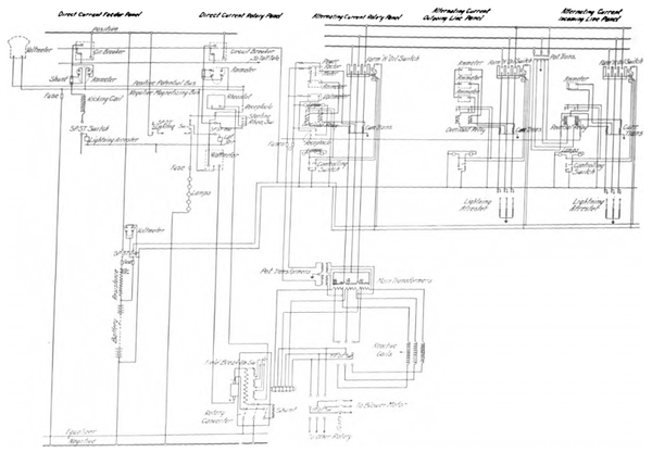 |
| Wiring Diagram of Sub-Station |
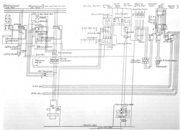 |
| Wiring Diagram of Main Station |
The road is operated under despatcher's orders given by telephone. At sub-stations train orders are received by the sub-station attendant for delivery. There are also telephone booths at all sidings and crossovers for emergency use when cars fall behind time. There are two telephone circuits the length of the line, one for despatching, the other for general business. Double-throw, double-pole knife switches at each telephone instrument make it possible to talk over either circuit from any instrument. Double-pole switches are provided at stations for cutting out sections of telephone line in case of trouble. Some device for automatically cutting out booth telephones when not in use will be installed, so that careless trainmen cannot leave a telephone bridged across the line to the detriment of the efficiency of the circuit and to fall a prey to lightning. The stationary telephones are all Stromberg-Carlson make. Each car carries a portable telephone to connect in along the line. These are made by the Garl Electric Company.
| |||
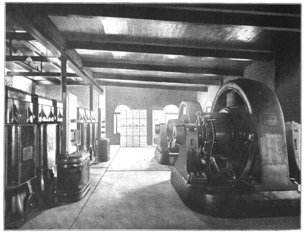
| Interior of Sub-Station , Aurora, Elgin & Chicago Railway |
The rates of fare are approximately 1 cents per mile, and are about half the regular steam-road fare between the points reached. Because of the present limited equipment no attempt has been made yet to meet the steam-railroad monthly commutation rates. All 5-cent fares are registered. Tickets are sold at sub-station waiting rooms and at terminals. Cash fares are receipted for by conductors with a ticket like that used on the Orchard Lake Division of the Detroit United Railway, which is illustrated else-where in this issue in an article on the passenger department of that system. The car shops are being built at Wheaton, where also are the operating offices.
At present writing the road has not been in operation long enough to have made it wise management to give the fast train service ultimately intended, because the roadbed is new and subject to settling, and the trainmen need time to get used to the service. The present service is a car every half hour from the terminal at West Fifty-Second Avenue to Aurora. The Elgin line is not completed because of lack of rails, and at present writing the Batavia branch is not open, although almost ready. The run to Aurora is made in 1 hour and 15 minutes, making all stops. Cars stop at platforms along the line only to receive or discharge passengers. Stopping platforms are all shown on the map. The time to Wheaton, 20 miles, is 42 minutes. There are twenty-four platforms in that distance, but in ordinary operation only about a quarter of these require stops. The present schedule speed is maintained with great ease, and gives the company good reason to think that with track ballast settled the local trains between Chicago and Aurora can make the distance in one hour. A through service, stopping only at Wheaton and at some points within the Chicago city limits, is contemplated, with a running time of 45 minutes. The distance is 34.6 miles. The time required to go from the Union Elevated loop in Chicago to Fifty-Second Avenue over the Garfield Park line of the Metropolitan Elevated is 30 minutes at present, and could be reduced somewhat by an express service, which may be put on. A 45-minute run from Fifty-Second Avenue to Aurora would mean that Aurora could be reached from the downtown district in Chicago in considerably less time and with less annoyance than on the steam roads, to say nothing of the greater frequency of the electric cars. The infrequency of the steam trains is one of their greatest drawbacks, as all Chicago people who have visited towns along the Fox River can testify.
| |||
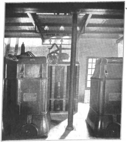
| Oil Switch and Transformers in Sub-Station |
However, this electric service needs no argument in its defense, because the traffic it has carried every day since it opened has demonstrated that the road is meeting a popular demand and also creating travel which did not before exist. Considering the newness of the road and the fact that some paving operations in Aurora have prevented the cars from running to the center of that city, or even leaving these out of account, the results are very gratifying. For two of the first weeks of operation the gross receipts from the half-hour local service between Chicago and Aurora were given by the management as $904.19 per day.
The service called for the operation of five cars. On Sundays the traffic has been enormous, and has sometimes swamped the ability of the company to take care of it, even with two-car trains. One Sunday, Aug. 31, with only five cars in operation, the receipts ran as high as $1,872. One gratifying thing about traffic so far has been the amount of through business between Chicago and Aurora, which constitutes the best and largest part of the business. And this is the very business which the increase in speed and operation to the center of Aurora will help. With the entire mileage of the road open for business, as it will be upon the completion of the Elgin and Batavia branches, and with fast through service inaugurated, it would not be unreasonable to expect that the gross receipts would be three times those at present. Allowing even a liberal percentage of this for operating and maintenance, as compared with other interurban roads, would leave enough for the investors in the securities to put the road on a solid financial footing. Of course, these are unusually prosperous times, and all rail-road earnings are abnormally high. On the other hand, while there may be temporary declines in receipts, the general average is sure to rise as time passes, because of the increase in the riding habit and the increase of population along the line. At the present time this road touches the southern edge of a number of old, thickly settled suburban towns. There is certain to be growth in these towns along the line of the road, as well as in the villages further out. Taken altogether, it is gratifying to know that the prospects for this enterprise are so good, for it is a matter of interest to many more than the investors in this company's securities. The financial outcome of such an electric railway undertaking as this has an important bearing on future development and investment in the electric railway field; a matter in which both the public and all connected with the electric railway business are interested.

