[Trade Journal]
Publication: Electric Railway Journal
New York, NY, United States
vol. 38, no. 7, p. 268-273, col. 1-2
Power Generation and Distribution System of
the Aurora, Elgin& Chicago Railroad
This Article Also Includes Notes About a New Exhaust Steam Turbine, a New and Reconstructed
Boiler Plant, Transmission-Line Reconstruction and the Supply of Energy for Lighting to
Municipalities and Farmers.
An account was published last week of the development of the Aurora, Elgin & Chicago Railroad and of the service given by that company. A description follows of the company's power station and distribution system.
All of the energy for operating the Aurora, Elgin & Chicago Railroad system and three connecting trolley lines, as well as lighting several cities, is generated in a large plant located near the Batavia terminal on the Fox River. At this point coal is obtainable over a nearby steam road and condensing water is taken from the river. The power plant includes several interesting additions made since it was described in the STREET RAILWAY REVIEW for August, 1902. It now has a daily average summer load of 115,000 kw-hours.
| |||
| Aurora, Elgin & Chicago Main Power Station |
The station building as originally constructed included an engine room, 198 ft. x 94 ft. in plan, and a boiler room, 198 ft. x 47 ft . in plan. The boiler room section has been lengthened 66 ft. to house additional equipment installed during the past year. The generating equipment as first installed included three 1500-kw, 2300-volt, three-phase, 25-cycle, revolving-field General Electric alternators driven by Cooper-Corliss horizontal cross-compound engines supplied with steam from eight boilers. As the load grew it became necessary to install a fourth engine unit and two additional boilers, thus completing the station as originally planned . All of the horizontal engine-driven units are still in active service and in addition a 3700-kw low-pressure turbine is operated.
The original boiler equipment with the additions for the fourth engine unit consists of ten Edge Moor boilers, each of 500-hp capacity, designed to operate at 180 lb. gage pressure. Each boiler has a 200-tube Green fuel economizer of 2700 sq. ft. heating surface located between the boiler and the main flue. Green chain grates with an area of 95 ft. each were installed with the boilers.
In 1909 the load had reached the capacity of the station, and as the result of a study of various plans for obtaining additional capacity, an order was placed with the General Electric Company for a low-pressure turbo-generating set. A high-vacuum surface condenser outfit of the Worthington type and additional boilers were also purchased.
LOW-PRESSURE TURBINE
The new turbine is of the mixed-pressure type so connected that a supply of steam at boiler pressure is available for immediate use by means of a special governor and set of valves. This system, when required, makes up deficiencies that may occur in the amount of exhaust steam from the engine-driven units which ordinarily operate the turbine. In case of emergency it is possible to operate the tur-bine entirely by the high-pressure supply and at an economy slightly less than that obtained with the condensing engines alone. At present the high-pressure system is used only for starting, and as soon as the turbo-generator has been synchronized with the engine-driven units the high-pressure steam supply is cut off and the unit is run on the exhaust from any two of the four reciprocating-engine sets.
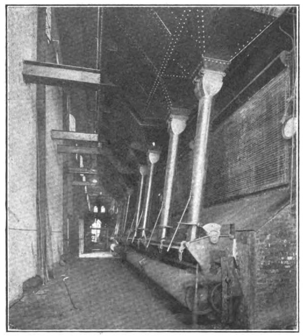
| |||
| Aurora, Elgin & Chicago Low-Pressure Turbine in Main Station |
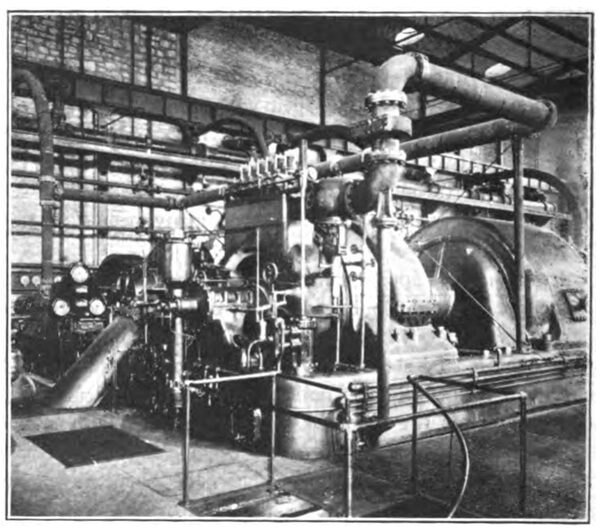
The low-pressure turbine is located in the center of the engine room and takes its supply of steam from a 22-in. exhaust header which extends the full length of the plant and into which all four engines exhaust. By means of suitable motor-driven sectionalizing valves in this exhaust header it is possible to obtain any combination of two engines supplying steam to the turbine, allowing the other two to operate independently on their own condensers. The turbine was selected of such a capacity as to be able to handle all of the exhaust steam from two of the reciprocating engines. Preliminary tests which have been made up to date would indicate that there is approximately an 18 per cent saving in the operation of the low-pressure turbine in connection with reciprocating engines over the same amount of output by the reciprocating engines alone. The company's engineers contemplate making exhaustive tests of this power installation in the near future and these will be made the subject of a separate article.
The new low-pressure turbo-generator was purchased as a 2500-kw machine on the old railway rating of a 35-deg. C. rise for continuous operation. This corresponds to approximately 3700-kw rating on the basis of the so-called "maximum continuous load." This machine has carried the latter load for considerable periods and more than 4000kw for short intervals. When operating normally all speed regulation for the system is done by means of the engine governors, but it is an interesting fact that with the turbine floating on the system the fluctuations in speed are very much decreased and the voltage regulation correspondingly improved. This seems to be due to the fact that the turbine absorbs most of the load fluctuations and thus allows the engines to run at approximately uniform loading.
BOILER PLANT IMPROVEMENTS
At the time the low-pressure turbine was installed the boiler house of the plant was extended to permit the installation of an additional equipment of four 500-hp boilers of the same manufacture as the original boilers. The new boilers were all equipped with Green chain-grate stokers, each having a 6-ft. flat arch and a grate area of 106 ft. This is an increase in grate area of approximately11.6 per cent over that of the earlier installation of boilers of the same horse-power rating. The new boilers are fifteen tubes high instead of twelve, and are installed with-out economizer equipment. Instead a Hoppes open feed-water heater was installed to utilize the exhaust steam from certain auxiliaries which formerly were electrically driven or exhausted to atmosphere.
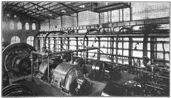
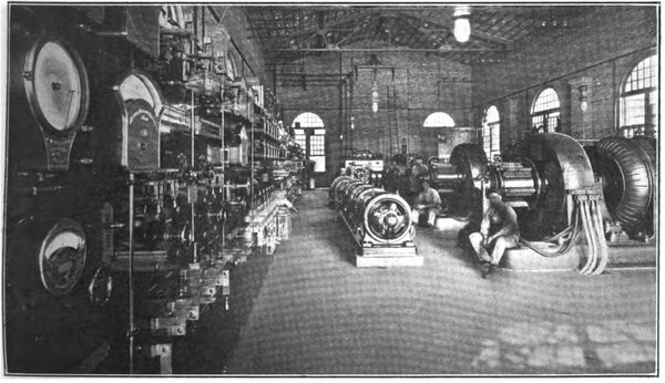
| |||
| Aurora, Elgin & Chicago Main Generating Station, Showing Low-Pressure Turbine in the Foreground |
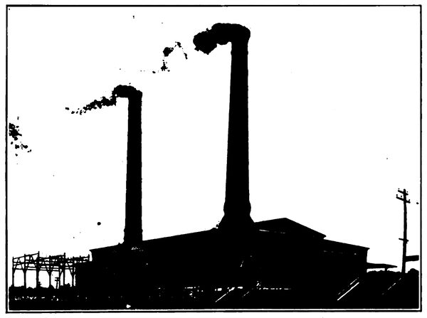
The installation of the new boilers necessitated the construction of a second stack, which was built at the end of the new boiler-house extension and has sufficient capacity for handling the exhaust gases from four more boilers when installed. The new stack was built of common hard-burned brick, exactly duplicating in design the original stack, and was made by the Heine Chimney Company. It has a height of 225 ft. above the boiler-room floor and its flue has a diameter of 11 ft. at the top. The power-plant equipment includes a Schaeffer & Budenberg stack-draft recording gage installed in the chief engineer's office.
BOILER PLANT CHANGES
In order to obtain the highest possible capacity from the older boiler plant several successful changes have been made in the installation. The stokers on the first eight boilers are being replaced by others of the chain-grate type, but having a larger grate area and being standard with those earlier mentioned for the new boilers. Suspended igniting arches 6 ft. long have also been installed. Another change which brought about improved combustion conditions was the lowering of the grates about 18 in. to increase the height between the grates and the lower tubes to 5.5 ft. In this way the combustion chamber was considerably enlarged. This reconstruction work, how-ever, required a lowering of the boiler-house floor, and this work was carried forward at the time the new stokers were installed. When the new stokers were installed the fire boxes were extended forward to form a half Dutch oven and at the same time new steel bunkers were erected to give additional coal storage capacity inside the plant. These improvements, together with better draft conditions ,due to the addition of the second large stack, make it possible easily to obtain 75 per cent over-rating from the boilers.
The new boilers have been equipped with water backs which supply water to the feed-water heater at about the boiling point. In installing the new chain grates coal pockets were provided in the floor in front of the boiler settings so that fine coal which leaks through the chain grates may be reclaimed into cars in the basement and thus save handling with shovels in the boiler room.
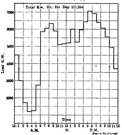
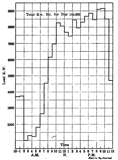 |
| Aurora, Elgin & Chicago Load Curve for July 4 |
Owing to the growth of the load it has been necessary to discard the original motor-driven triplex boiler-feed pumps and in their places have been installed a steam-driven duplex boiler-feed pump of the pot-valve type and an Alberger steam turbine-driven 6-in. centrifugal, four-stage boiler-feed pump, either one of which has sufficient capacity to handle the entire boiler feed-water requirements for some time to come.
Other miscellaneous improvements in the power plant included the installation of motor-operated valves with re-mote control for the high and low-pressure steam lines. By the use of these valves it is possible to shift the tur-bine steam supply conveniently and quickly from one group of reciprocating engines to another.
But few changes have been made in the electrical equipment other than the addition of control panels for the new turbo-generator and the installation of a 2400-amp, 125-volt exciter driven by a 450-hp, 2300-volt General Electric induction motor.
| |||
| Aurora, Elgin & Chicago New Boilers, Bunkers and Dutch Ovens |
A small machine shop has been added on the gallery at one end of the engine room so that most of the repair work on the engines and power-plant equipment can be done by the station employees.
This power house is now feeding 175 miles of track for the Aurora, Elgin & Chicago line, 28 miles for the Aurora & DeKalb line, 34 miles for the Elgin-Belvidere line and 11 miles for the Aurora-Joliet line. In addition it sup-plies current for all the lighting in the city of Elgin, for seven smaller municipalities and for a number of small motor installations fed from the 600-volt distribution lines, as described later. The accompanying diagram shows the growth of the total output of the generating station since1904. During that year the output of the plant was 18,667,-000 kw-hours. Last year the output was 38,764,000 kw-hours.
 |
| Aurora, Elgin & Chicago Typical Weekday Load Curve for Generating Station |
Accompanying load charts show the typical power-station loading for a weekday and also show the load for the Fourth of July this year. The shape of the curve is controlled very largely by the service on the third-rail divisions, but the lighting and street railway service assist materially in increasing the daily load-factor.
POWER DISTRIBUTION
Energy is distributed from the main generating station of the Aurora, Elgin & Chicago Railroad at 26,400 volts. It is transmitted over three aluminum-cable, high-tension transmission circuits extending one each to the north, east and south. The general arrangement of the transmission system is in the form of a triangle with an extension from each corner. Any side of this triangle may be opened and yet all substations receive current. One line extending north runs across country to connect with the Geneva branch near West Chicago, and the Elgin branch at Ingalton, from which point it branches in both directions following the right-of-way to Elgin and through Wheaton to Lombard. A second transmission line extends across country south from the power plant to Aurora. The third line extends eastward along the interurban right-of-way through Wheaton to Lombard, where it is joined by the line which follows the Elgin branch from Ingalton. The duplicate lines are carried on the same poles between Wheaton and Lombard. From Lombard a single trans-mission line extends east to Maywood.
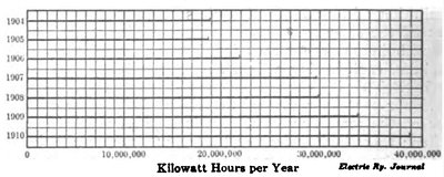 |
| Aurora, Elgin & Chicago Diagram Showing Total Output of Generating Station by Years |
The company plans to build during the coming year a duplicate pole and transmission line from Ingalton to Elgin. This will insure, when completed, a continuity of supply for the lighting substation at Elgin, which now is fed over the present single line and consequently has been subject to temporary interruptions. It will also be of assistance in maintaining continuous power supply for the Clintonville railway substation, which supplies power for the Elgin city lines and interurban lines in that vicinity.
As originally installed the high-tension transmission line had a 30-in. equilateral triangular spacing, but this has been increased to 65-in. spacing. It was found with the smaller spacing that the line wires could be easily short-circuited from accidental causes or by maliciously inclined persons, and the 26,400-volt arcs in many cases would hold long enough to burn in two the wires or to blister them so that the first cold snap would part them. Since the reconstruction of the line very few interruptions have taken place.
| |||
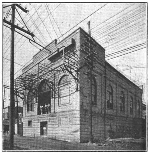
| Aurora, Elgin & Chicago Substation at Elgin |
The high-tension line was reconstructed without impairment to the service. On the triangular loop, which has earlier been described, the work of reconstructing the line was carried on in the daytime. One side of the loop can be cut off at any time and still all substations be supplied. The reconstruction work on the extensions from the corners of the loop was done by working three hours each night when car service was lightest.
| |||
| Aurora, Elgin & Chicago Elgin Substation |
The insulators installed at the time of reconstruction were the Locke No. 307, a three-part porcelain type which now is obsolete. For present maintenance and extension work on the 26,400-volt lines the Ohio brass No. 9413 insulator is used. This also is a three-part insulator weighing 8 1/4 lb., designed for 35,000-volt line voltage and 90,000-volt test voltage.
ROTARY CONVERTER SUBSTATIONS
The third-rail division of the Aurora, Elgin & Chicago is supplied with 600-volt current by seven rotary converter substations, two of which-those at Clintonville and Aurora-also feed the Fox River trolley line and the local street railway systems. The power-plant installation includes a rotary converter substation equipment for feeding both the third-rail division and the Fox River line. The total rotary converter capacity is 8500 kw.
| |||
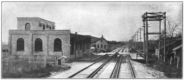
| Aurora, Elgin & Chicago Substation, Depot and Portable Substation at Maywood |
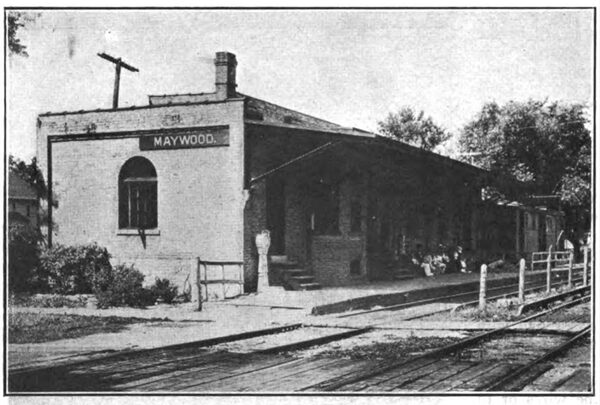
No new railway substations have been added to those originally built, but it has been necessary from time to time to increase the equipment in each substation as demanded by the increased train service. The original equipment of each substation included two 500-kw General Electric rotary converters with accessory apparatus. A third 500-kw unit has been installed in each of three of the substations, while in another that at Lombard one 500-kw rotary has been replaced by a 1000-kw rotary. The Maywood substation carries the largest load, and this has three 500-kw rotaries and is assisted by a portable sub-station having one 500-kw rotary. The company has standardized on 1000-kw rotaries for future additions.
| |||
| Aurora, Elgin & Chicago Combination Depot and Substation |
The only other substation changes of note have been the substitution of inverse time-element relays on all high-tension feeders and the replacement of the original 26,000-volt lightning arresters with the multi-gap type arresters made by the General Electric Company. These changes have been important in reducing interruptions to service.
THIRD-RAIL DETAILS
Some of the standards of construction on the 600-volt distribution system may be of interest. The type of third-rail was described in the issue of this paper for Aug. 5. The third-rail, of 100-lb. section of soft steel, is electrically continuous throughout the length of the road and is subdivided at the switchboard feeder panels only. On the Wheaton-Chicago double-track section the two third-rails are operated in multiple and thus furnish a carrying capacity approximately equivalent to 4,000,-000 circ. mil cross-section of copper. No supplementary feeders are used on the third-rail division, and this road, by reason of the large carrying capacity of its third-rail, is particularly fortunate in being thus able to maintain high average voltage conditions. Tests made over considerable sections of tracks, including numerous highway crossing cables, show the third-rail leak-age to average 0.6 amp per mile of track on 600 volts. This leakage is practically the same in wet and dry weather. All new work and replacements are being done with the Ohio Brass Company's porcelain insulators.
THIRD-RAIL HIGHWAY CROSSING CABLES
On the third-rail division it is necessary, of course , at all street and high-way intersections to break the third-rail and carry the current underground. The connecting cables spanning these highway gaps as originally installed consisted of paper and rubber-insulated copper cables of 1,500,000 circ. mil and 2,000,000 circ. mil cross-sectional area, sheathed with lead and protected by jute. These were installed underground and protected only by having 1-in. boards placed above them. Insulating terminal heads furnish weatherproof outlets of large cross-section. The terminal heads are connected with the base of the third-rail by compressed terminal stranded bonds of Electric Service Supplies Company manufacture. So much trouble was experienced by the burning out of these high-way crossing cables that a special construction was developed.
As installed in the new way the cables give excellent service. Ordinary rubber-covered cable is used in place of he expensive lead-covered, paper or rubber-insulated cable. The cable is pulled into a 3-in. bituminized fiber conduit entirely incased in concrete. The sections of conduit are carefully joined and at each end of the cable aright-angle bend serves to bring the cable above ground at the proper location. The terminals of the cables are protected from the weather by concrete or porcelain caps. The original method of connecting to the rail is still followed. The maintenance cost of the third-rail and its highway crossing cables is $55 per mile of rail per year. The maintenance crew for the third-rail division, which cares for approximately 100 miles of third-rail and transmission line, consists of one electrical man, a foreman and five repair men. This crew also has charge of the high-way crossing cables. During the past year the company has rebuilt a consider-able portion of its city overhead system with No. 00 trolley wire and its interurban trolley lines with No. 000 wire ,and also has installed considerable additional 500,000-circ.mil feeder cables on the trolley lines.
