[Trade Journal]
Publication: Electric Railway Review
Chicago, IL, United States
vol. 17, no. 10, p. 322-326, col. 1-2
OPERATION AND CONSTRUCTION OF THE ELGIN &
BELVIDERE RAILWAY.
BY R. H. RICE.
The formal opening on February 2, 1907, of the interurban line between Elgin and Belvidere, Ill., brought into the electric railway field a high-speed line that has exceptional opportunities for developing a rapidly increasing through traffic in the territory served by it and by the line with which it connects. This new line is the property of the Elgin & Belvidere Electric Company and extends from Elgin in a northwesterly direction to Belvidere, a distance of 36.5 miles.
Route and Connections.
The road connects at Elgin with the Aurora Elgin & Chicago Railway (the third rail to Chicago), also with the trolley line operated by the same company extending to Aurora and connecting with other roads to points beyond. At Belvidere connection is made with the Rockford & Interurban Railway operating west from Rockford to Freeport. From Rockford, the Rockford Beloit & Janesville Railroad operates a line north which will afford a direct route to Madison when extended. A short extension from Marengo may possibly be built northward to Harvard, thus making connections with the Chicago Harvard & Geneva Lake Railway, affording transportation to Geneva Lake from Chicago and intermediate points.
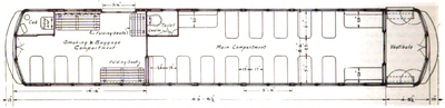 |
| Elgin & Belvidere Electric Company Plan of Combination Car. |
The region through which the Elgin & Belvidere Railway and its immediate connections pass is a well settled and prosperous community and offers opportunities for a large passenger and freight traffic.
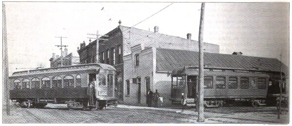
The operating office of the Elgin & Belvidere Electric Company is at Marengo, Ill. The building occupied by the company is located at the intersection of the two main streets of the town and provides a waiting room, ticket office, freight room, trainmen's quarters and superintendent's office. The substations at Gilberts, Union and Garden Prairie contain passenger, freight and baggage rooms. At Elgin and at Belvidere waiting stations are jointly maintained, by the Elgin & Belvidere Electric Company and the connecting railway companies with which it has a mutual working agreement. The Belvidere terminal is shown in one of the accompanying illustrations. The schedules have been arranged so as to give patrons close connections with all trains running east, west or north. By this arrangement what is practically a through service from points north and west of Belvidere to Chicago and all points on the Aurora Elgin & Chicago Railway is obtained.
| |||
| Elgin & Belvidere Electric Company Belvidere Terminal, Showing Elgin & Belvidere and Rockford & Interurban Cars. |
The running time between Elgin and Belvidere is now one hour and forty-five minutes, but as soon as the track has settled, the time will be reduced to one and one-half hours. An hourly schedule is maintained in both directions. Regular agency stations are maintained at Elgin, Gilberts, Huntley, Union, Marengo, Garden Prairie and Belvidere. Stops are regularly made at these stations and upon signal cars will pick up passengers at any of the principal highway crossings along the line. Limited trains will later be added to the service.
The regular meeting points for cars are at Almora, 3 1/2 miles from Elgin, Smith's Siding, 17 miles from Elgin, and Thorne's Siding, 27.4 miles from Elgin. In addition to these regular meeting points sidings are provided at Gilberts, Marks, Huntley, Coyne, Marengo, Garden Prairie and Camp Epworth.
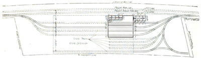 |
| Elgin & Belvidere Electric Company Plan of Car House and Yards. |
The Stromberg-Carlson telephone system is used for dispatching trains. The main switchboard is located in the ticket office at Marengo and telephone booths are maintained at each of the agency stations. Jack-boxes are conveniently located on poles every 2,000 feet along the line and as each car is equipped with a portable box telephone ,the trainmen can, in case of trouble, quickly get into communication with the dispatcher. The standard interurban train order system, as recommended by the committee of the American Street and Interurban Railway Association, has been adopted.
Track and Overhead Construction.
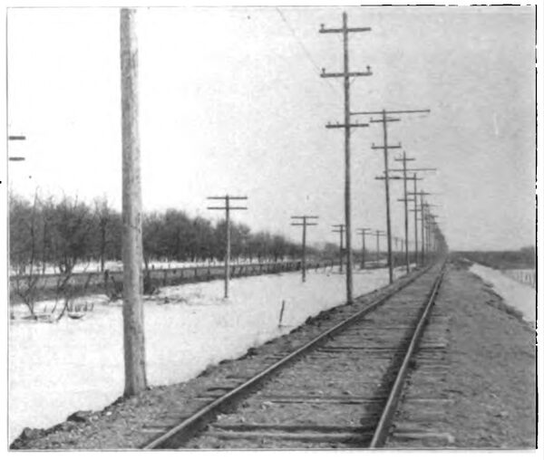
The railway is built on private right of way except through the towns. Excessive grades and short radius curves have been avoided. The longest tangent, 7 miles long, is just west of Marengo. There are also many shorter stretches of straight track that will figure prominently in running trains on a fast schedule. There are no grade crossings with railroads and the number of highway and farm crossings is not large. The line passes under the Chicago & North-western and the Chicago Milwaukee & St. Paul railroads.
| |||
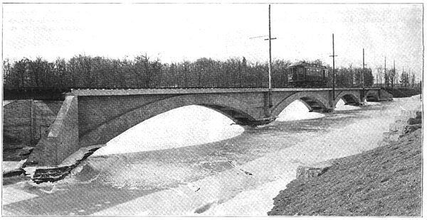
| Elgin & Belvidere Electric Company Kishwaukee Bridge. |
The subway under the Chicago Milwaukee & St. Paul Railway near Almora is of concrete construction. The tunnel is 43 feet long and has a width of 14 feet and a clear height above the top of the track rails of 20 feet. The sides of the tunnel spread out into wing walls at the ends. The trolley is supported from mine hangers fastened to the under side of a wooden trough. The telephone lines and trolley feeders are carried through the subway on brackets set into the side walls near the roof, while the high-tension lines are taken over the track and telegraph lines of the railroad company. The transmission line wires are mounted on 60-foot poles set 50 feet center to center. Protection is afforded by a guard net placed 25 feet above the railroad tracks. Standard overhead equipment furnished by Porter & Berg and the Ohio Brass Company has been used throughout. The copper wire was furnished by the American Steel & Wire Company.
A bridge over the Kishwaukee river is one of the interesting points in the roadbed construction. It is of the ribbed concrete-steel type, having four arches each 872 feet in length, and a solid concrete floor with 12-inch concrete stringers for retaining the ballast under the track. The approaches are built up on pile bents filled in with earth. Details of the methods employed in building this bridge were given in an article in the Electric Railway Review of August, 1906, in which many details of the track and overhead construction were described.
| |||
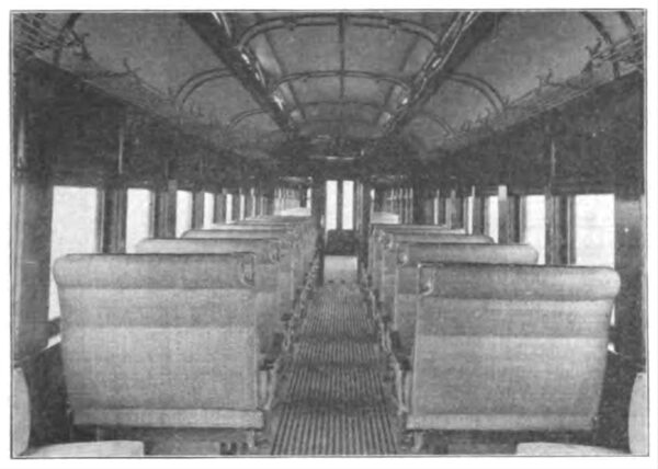
| Elgin & Belvidere Electric Company Interior View of Passenger Car. |
Power is purchased from the Aurora Elgin & Chicago Railway and is transmitted from its Clintonville substation, across the country and around Elgin to the right of way of the Elgin-Belvidere line. The current is three-phase, 25-cycle at 26,400 volts, which is stepped down and distributed from rotary-converter substations at Gilberts, Union, and Garden Prairie, approximately 10 miles apart. The three buildings are practically alike in construction and were described in the article previously mentioned, in which a vertical section illustrates numerous features. A foundation plan of the substations at Union and Garden Prairie is presented herewith and illustrates some features not shown in the vertical section.
| |||
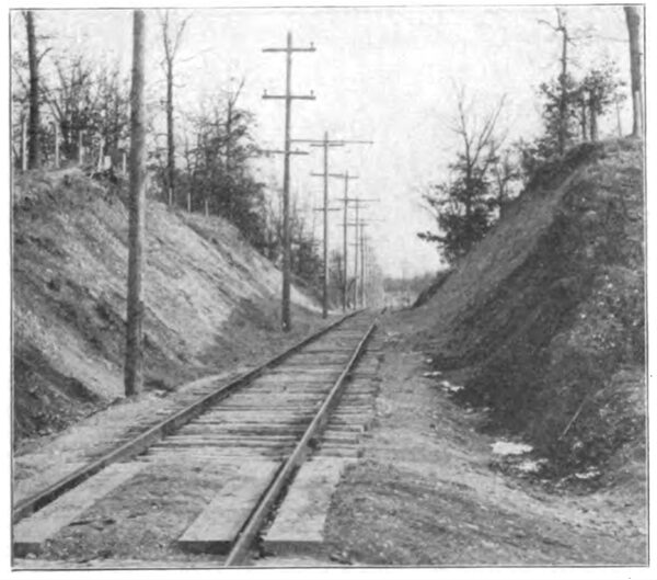
| Elgin & Belvidere Electric Company Typical Cut. |
The main portion of each substation is 29 feet 3 inches by 30 feet 5 inches and in the rear is an extension 11 feet8 inches by 25 feet 7 inches, extending 16 feet above the ceiling of the main portion of the building. This tower receives the incoming high-tension lines on a rack fastened outside the front wall of the building, the wires being carried over a parapet wall on two 45-foot poles located opposite the front of the building. All wires are supported by Locke No. 606 high-tension strain insulators. The wires enter the building through porcelain tubes mounted inside of three concentric fiber insulator tubes and pass through lightning arresters and oil disconnecting switches. Beyond these the line conductors are separated by brick barriers. The main high-tension lines pass out of the building in a manner similar to the incoming lines, the arrangement virtually making a loop of the high-tension lines into the building.
The local lines, which are tapped off from the main conductors in the barriers, pass through lightning arresters, choke coils and oil disconnecting switches.
| |||
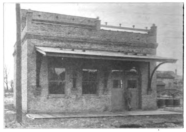
| Elgin & Belvidere Electric Company Substation at Union, Ill. |
The lightning arresters are of General Electric 26,400-volt, three-phase, multiplex type and the oil-cooled choke coils are also of General Electric manufacture. The three transformers, which are delta connected on both the primary and secondary sides, are each of 110 kilowatts capacity and step down the voltage from 26,400 to 370 volts. The three transformers feed into an alternating-current rotary panel of the switchboard which is thoroughly equipped to control the rotary.
| |||
| Elgin & Belvidere Electric Company 7-Mile Tangent West of Marengo, Ill. |
The three-phase, 25-cycle, rotary converters are of 300 kilowatts capacity, designed for 370 volts on the alternating-current end. The direct-current voltage is 600, the current being fed into a direct-current switchboard containing two feeder panels of 1,200 amperes capacity serving the trolley line. The feeder panels are equipped with a 1,200-ampere General Electric C. P. circuit breaker, a 1,500-ampere T. F. T. ammeter with shunt, and a 1,500-ampere single-pole single-throw quick-break main switch. All of the electrical equipment, including the rotary converters, switchboards, transformers, oil switches, choke coils and instruments, was furnished by the General Electric Company and consists of their standard type of apparatus designed for this work. At present one rotary converter only is installed in each station. The space left for additional equipment is shown in the accompanying ground plan of the substations. The location of the conductors connecting the various pieces of apparatus may also be seen.
All wiring is done in 3-inch tile ducts imbedded in the concrete floor as shown by the section along BB.
Rolling Stock.
The passenger cars used on the line are of the Pullman double-truck single-ended vestibule type manufactured by the St. Louis Car Company. An exterior view is shown in the illustration of the Belvidere terminal. The cars have an overall length of 47 feet 1 inch, a width over sheathing of 8 feet 6 inches and a height of 9 feet 4 inches from the under side of the sills to the top of the roof, which is of the monitor deck construction over the entire body.
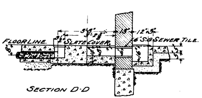 |
| Elgin & Belvidere Electric Company Section Through High-Tension Ducts. |
The interior of the car is divided into two compartments, the main portion being in accordance with standard interurban practice, having transverse rattan seats of the walk over pattern. The interior finish is of dark mahogany with a ceiling decorated in green and gold and finished with bronze metal fittings. The arrangement of the smoking compartment is somewhat out of the ordinary. The motor-man's cab is located at the forward end on the right side ,as shown in the detail plan. This allows the left side for the use of passengers, affording an unobstructed view from the transverse seats. Back of the motorman's cab is a sliding baggage door. By dropping the three longitudinal folding slat seats, ample space for baggage is provided when necessary. Heating is secured by a Peter Smith No. 2 magazine coil heater, located in the smoking compartment. Α speaking tube is provided to afford communication between the motorman's cab and the rear vestibule.
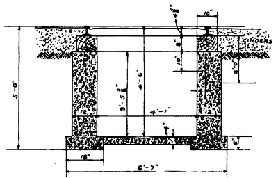 |
| Elgin & Belvidere Electric Company Section Through Concrete Track Pits. |
While the car is intended to run forward under normal conditions, a controller and air equipment has been provided in the rear vestibule to allow backward running if necessary. Two trolley poles are also provided to facilitate running under such conditions. The trolley harps and wheels were supplied by the General Electric Company. The motor equipment, furnished by the same company, consists of four 74-horsepower motors, with parallel controllers, and all necessary auxiliary devices. The total weight of these motors is about 15,000 pounds.
The interior lighting is furnished by 25 incandescent lamps and an arc headlight is fitted at the forward end. All the wiring is placed in concealed iron conduit.
The car is equipped with a truck pilot on the forward end which is so arranged as to permit of two cars being coupled head on. The total weight of the car with its equipment is 32 tons.
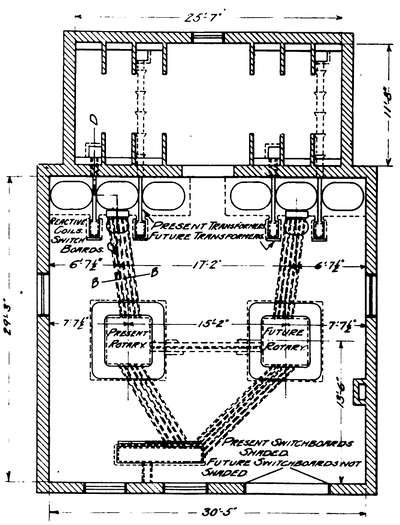 |
| Elgin & Belvidere Electric Company Plan of Rotary-Converter Station. |
The baggage and express cars used on the line have double trucks and are 45 feet long over all and 8 feet 6inches wide. These cars are made to conform in general exterior appearance to the passenger cars. They are equipped with four G. E. 65-horsepower motors and straight airbrake equipment, being intended to run at a maximum speed of 30miles per hour.
Car House and Shops.
The car house and repair shops are located just outside of Marengo. The main building, 91 feet by 105 feet in area, is of brick, concrete and steel and is divided longitudinally into two equal bays, one of which is designed for the car repair work and the other for car storage purposes. The machine shop, which is equipped with a lathe , drill press and other tools essential in repairing cars, occupies the north-east corner of the bay set aside for the car-repair work. The structure is lighted by four saw-tooth skylights which extend the length of the building. An addition 21 by 50 feet in floor area has been constructed at the northeast corner of the main building. In this portion are located a boiler room, and a coal and oil storage room. The superstructure of the building is of brick and the roof of frame construction.
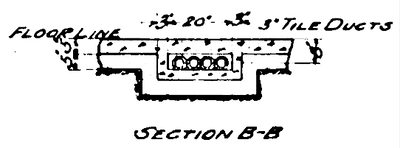 |
| Elgin & Belvidere Electric Company Section Through Low-Tension Ducts. |
The Arnold Company of Chicago had charge of the entire engineering and construction work, which was supervised by George A. Damon, managing engineer, George Weston, civil engineer, E. N. Lake, electrical engineer, and W. H. Rosecrans, superintendent of construction. The general offices of the Elgin & Belvidere Electric Company are at 181La Salle street, Chicago, and the operating offices are at Marengo, Ill., as before stated.
