[Trade Journal]
Publication: The Railway & Engineering Review
Chicago, IL, United States
vol. 47, no. 10, p. 181-184, col. 3,1-3
The Elgin & Belvidere Electric Railway.
The most recent piece of important electric interurban railway construction in northern Illinois is that of the Elgin & Belvidere Electric Co., connecting the two cities named. This road, which was formally opened for traffic February 2, 1907, is 36 miles in length; and its location is such that its completion makes material changes in the interurban railway map of Illinois. Elgin has long been connected with Aurora and with Chicago by the high-speed, third-rail line of the Aurora, Elgin & Chicago R. R.; and Belvidere is the eastern terminus of the Rockford & Interurban Ry., which extends to Rockford and beyond to Freeport, Ill., and to Beloit and Janesville, Wis. The Elgin & Belvidere line is therefore in the position of a connecting link between systems of considerable magnitude, and may be expected to derive a good part of its revenue in that way. But aside from the more remote territory from which the road is in position to draw traffic, the country which is immediately tributary has a large and prosperous population. Elgin is a city of 23,900 inhabitants and an adjacent population of 5500; and Belvidere has a population of 9000, with 2000 in the immediate vicinity. Situated along the line between the two cities are a number of villages of which Union and Marengo are the largest, with populations respectively of 700 and 2200. Taken as a whole the line is without doubt most advantageously situated with regard to possibilities of future patronage.
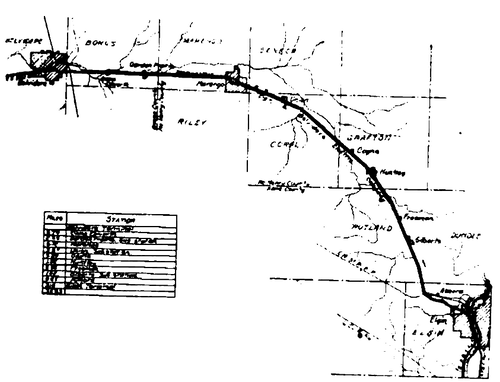 |
| Fig. 1 Map Showing Interurban Line of the Elgin & Belvidere Electric Co. |
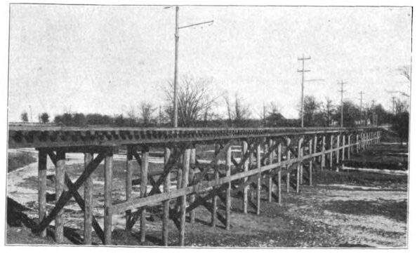
The country traversed by the line is very favorable for economical construction, it being nearly level for almost the entire distance. Under these circumstances it was possible to adopt a minimum grade, and to avoid any objectionable amount of curvature. The road is therefore constructed for operation at high speed, and except for those parts which lie in the cities and towns, is located on private right of way 50 ft. wide, throughout its length. The earthwork involved in the construction was relatively small, though the grading was sufficiently liberal to insure a roadbed of the most permanent character. There are several tangents of considerable length on the line, the longest being west of Marengo for a distance of six miles. The most notable bridge is that at the Kishwaukee river, between Garden Prairie and Belvidere. This bridge is entirely of concrete, in four 872-ft. arches. It is single-track, and with ballasted floor throughout. Some novel methods were employed in its erection, by the Strauss Bascule & Concrete Bridge Co.; but space will not permit further reference at this time. The longest trestle is that shown in the accompaying [sic] accompanying illustration, Fig. 2, located near Elgin.
| |||
| Fig. 2 Trestle Near Wing Road, Elgin. |
The standard roadbed has a width at grade line of 14 ft. on embankments for single track, and a width of 27 ft. at sidings. In excavations the width of the roadbed at grade line is 18 ft. for single track and 31 ft. at sidings, this including ditches. The ballast on private right of way is of gravel to a depth of 6 inches below the ties. It is brought to the top of the ties at the center of the track, and sloped to an elevation two inches above the bottom of the tie at the end of the tie and dressed to a curved line intersecting the sub-grade two feet from the end of the tie.
The standard adopted for bridging and trestlework includes, in general, pile bents 16 ft. center to center, four piles to the bent. These are capped by 12 x 12-in. timbers, carrying two chords of two 8 x 16-in. stringers each, in 32-ft. lengths and broken joints. Every sixth bent on trestles is fitted with a pole support. Ties on trestles are 6 x 8 ins. by 10 ft. Guard rails are 6x8 ins. in size, dapped to the ties, lap-jointed, and all drift bolted and spiked. Wooden culverts are of 12 x 12-in. timbers in the side walls stepped back at the ends to a slope of12 horizontal to 1 vertical. They are covered by 12 x 12-in. timbers dapped upon the inside to take the thrust of the side walls. All timbers mentioned are yellow or white pine except the 8 x 16-in. stringers which are of fir. Piles are of white oak, burr oak, cedar or cypress, and the minimum size is 8 ins. at small end and 12 ins. at the butt. In sinking them they were driven until a blow from a 2000-lb. hammer at a hight [sic] height of 25 ft. produced a movement of only one-half inch. The standard tile drains are of 12-in., 15-in., 18 and 24-in. vitrified clay pipe, and they are generously placed to care for the maximum amount of moisture. In wet cuts 4-in. farm drain tile are laid at a depth of 3 ft. beneath the outside ditches.
The track is of 70-lb. T-rails, 33 ft. in length. The joints are staggered and fitted with 4-bolt, 22-in. Weber splices. The ties are of tamarack, hemlock and cedar, and are spaced 17 to each 33-ft. rail. The minimum sizes for tamarack and hemlock is 6 by 8 in. by 8 ft., while of cedar the minimum is 5 and 6-in. face and 7-in. thickness. All curves are fitted with a guard rail of the same section as the running rail. Turnouts are split switches and No. 8 spring frogs, guarded; and at through turnouts spring switches of the same description are used. The rail joints are bonded with one bond of the Ohio Brass Co's. spectacle type, 11 1/2 ins. long, soldered to the web of the rail, and of 0000 capacity. At intervals of 1000 ft. 0000 cross bonds connect the opposite rails. The right of way is fenced with woven wire fencing of the American Steel & Wire Co. In hight [sic] height, the standard is 45 ins., eight wires, with one strand of Glidden two-point barbed wire on the top. Wing fences at cattle guards are of frame construction of 1 by 6-in. boards. The standard posts are 4 ins. in diameter at the top, 7 ft. long, with 2 ft. 6 ins. in the ground. On straightaway fencing braces are provided four to the mile, these being of No. 9 wires twisted. The posts at these points are 5 ins.in diameter, 8 ft. long and 3 ft. 6 ins. in the ground.
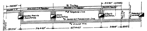 |
| Fig. 3 Diagram of Electrical Transmission System, Elgin & Belvidere Electric Railway. |
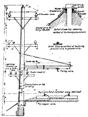
Energy for operation of the line is obtained from the electrical system of the Aurora, Elgin & Chicago R. R. The Clintonville substation of that road is located 3 3/4 miles south of Elgin, and at that point the transmission system of the Elgin & Belvidere road, receives the power. The distribution system, which is shown diagramatically [sic] diagrammatically in the accompanying illustration, Fig. 3, includes as its principal element a high-tension transmission system which carries the three-phase alternating current at 26,400 volts to the several substations along the line. At these substations the current is transformed to 600 volts direct current, and distributed along the trolley wire through low tension feeder wires as shown in the diagram. The typical arrangement of the overhead system is shown in the accompanying illustration of the standard pole, Fig. 5. Fixed to the extreme top of the pole is the ground wire. The two upper cross arms carry the high-tension wires; and the lowest cross arm carries two telephone wires and the low-tension feeder. This arrangement, while standard, is departed from on those parts of the line where the full complement of wires, as named, is not required. Moreover, in passing through cities, the bracket-arm construction as shown is abandoned for span wire suspension. At these places, one line of poles carries the wires arranged approximately as shown, while the opposite pole line is of shorter poles and serves only to support the span wires. Through the streets of Marengo, where the span wire suspension is used, the pole line which carries the high-tension system is of 60-ft. poles, 8 ins. diameter at the top, these being the longest used on any part of the system.
| |||
| Fig. 4 Long Tangent West of Marengo. |
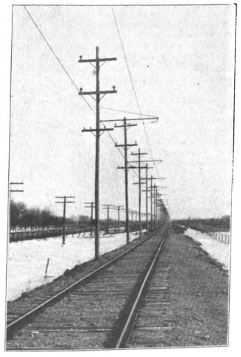
The standard pole where the bracket-arm suspension is used varies between 30 and 40 ft. in length, and is of cypress, 7 ins. in diameter at the top. All poles are roofed on the top and the roof painted one coat. The poles used in the cities are painted one coat before erection and one coat afterward. The poles are spaced 100 ft. apart, and are set 7 ft. in the ground. They are placed 7 ft. from the center line of the track, on the right hand side, facing Belvidere. They are set vertical on straight line, but on curves up to 3 degs. they are given a slight rake in order to draw up to vertical. On sharper curves the poles are braced. In soft ground an effective anchorage is provided in the shape of an A frame, which extends horizontally from the pole into the roadbed, and is firmly fastened there beneath the track to six 2 x 4-in. stakes driven into the ground. The poles are freely guyed at corners and curves, and even on straight lines, head guys are located at intervals. The cross arms for the high-tension wires are of southern pine, 3 3/4 x 5 ins. by 6 ft. The lowest cross arms which carry the telephone wires and the feeder, are 3 1/4 x 4 1/4 ins. by 5 ft.
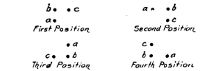
The high-tension conductors are three No. 6 copper wires, carried on the two upper cross arms, and their arrangement thereon varies between the four insulators as shown. This variation of the position of the wires is the means taken to effect the transposition, and is necessary to avoid the interfering effect of the alternating currents. The wires are transposed to make two complete turns between Garden Prairie and Union, three between Union and Gilberts and two between Gilberts and Clintonville. In effecting this the wires are led successively onto the vacant insulator on the crossarm, the arrangement taking four successive positions as shown in the diagram herewith, Fig. 6. The insulators which support the wires are of chocolate colored glazed porcelain, high-tension Locke No. 408-A, designed for the voltage carried. They are made in two pieces cemented together, and are 8 ins. in diameter and 7 ins. high, with the groove for the conductor at the top.
 |
| Fig. 5 Standard Pole Arrangement, Elgin & Belvidere Electric Ry. |
An interesting detail of the transmission system is the provision of the ground wire along its entire length, and the effective arrangement for grounding it at frequent intervals, wire consists of No. 6 solid galvanized iron wire. The ground It is attached to the pole by a lag screw driven vertically into the washers under the head of the screw. apex, being held between fifth pole to provide for grounding of the wire, a At every strip of No. 22 galvanized band iron 3/4-in. wide is held at the end beneath the lag-screw washer and led down the pole. It is securely fastened to the pole by nails at 18-in. intervals and comes to an end at the lower extremity of the pole. The ground strip is there riveted to these bands of galvanized iron which encircle the base of the pole a few inches apart. At the poles where the ground strip is attached to the ground wire, a piece of No. 6 iron wire is tied to the lag screw at the top of the pole and left with the end loose and extending up-ward 6 ins. At the points of transposition the ground wire is supported some inches above the top of the pole by an extension provided for the purpose, this being done to insure proper clearance between the ground wire and the high-tension wires. All guys which extend to within 6 ft. of the ground are connected to the ground wire.
Lightning arresters are installed on every twentieth pole in the position shown in the illustration. These lightning arresters are of a type designed for 600 volts direct current and are mounted in weather-proof boxes. The ground wire from the arrester is No. 6 B. & S. copper wire, and it is led down the pole along the ground strip and soldered thereto by an effective fastening. At the foot of the pole the ground wire passes into the ballast under the track and connects with a 0000 cross bond attached to both rails. At the Kishwaukee river and at two other points on the line, stations 1065 and 1647 respectively, ground plates of 1/8-in. sheet copper, 12 x 24 ins. in size, are buried in the embankment below water level, and connected by No. 0 copper wire to both the ground wire and the rails .The company which installed the lightning arresters made the guarantee that by virtue of the ground wire and the ground strip, as above described, efficient protection from lightning effects could be insured with the use of only 50 per cent of the number of arresters that would otherwise be required.
 |
| Fig. 6 Diagram of High-Tension Transportation. |
The low-tension, direct-current feeder parallels the entire length of the line and distributes the current along the trolley wire, from the three sub-stations. The size of this feeder is 300,000 circular mils. It is supported on Locke No. 47 insulators of glazed porcelain, one piece, double petticoat, and 4 ins. in diameter by 3 ins. in hight [sic] height. At substations an 800,000 c.m. feeder leads the return current from the track into the building. The telephone wires, which are carried on the same cross arm, are copper No. 12 B. & S. gage on Locke No. 12 insulators. The telephone wires are transposed at every fifth pole. Telephone jack boxes are provided at frequent intervals , at which the portable instrument carried on the car may be plugged in to afford communication with any part of the system. Located on the poles at certain intervals are section tie switches, by which sections of the trolley wire and feeder may be isolated or thrown together at pleasure. These are single pole, quick-break knife switches with auxiliary contacts and terminals, and they are mounted on slate bases in weatherproof boxes. The cover to the box may be locked in either the open or the closed position.
| |||
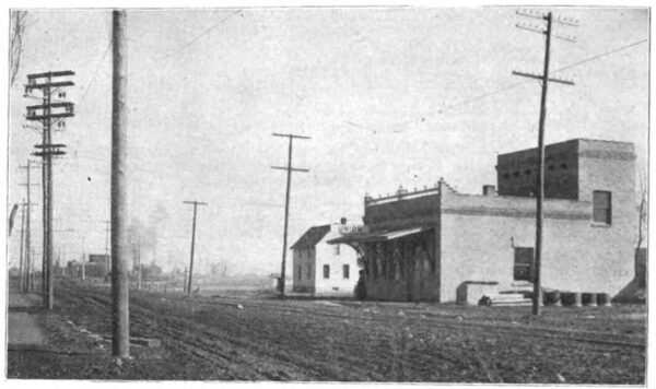
| Fig. 7 Substation at Union, Elgin & Belvidere Electric Ry. |
The bracket-arms which support the trolley wire are of the common type, of 12-in. structural steel tubing. 9 ft. in length. Where span suspension is used, the span wire is 5-16-in. galvanized strand. Two wood strain insulators, 1 x 9½ ins., with galvanized malleable fittings are inserted in the spanwire, one on each side of the trolley. The normal hight [sic] height of the trolley wire is 19 ft. above the ground ;and the sag of the wire at the time of erection was limited to 4 ins. per 100 ft. The trolley wire is000 grooved copper. Very complete arrangements are taken for anchoring the trolley wire, guys of 1/4-in. strand being used every 2000 ft. These guys are fastened to the trolley wire by strain ears clamped and soldered to the wire, and head guys are run to the poles at every anchorage. The feeder wire is tapped into the trolley at intervals of 1000 ft. Split T clamps are used for the purpose and the method may be seen in the illustration of the standard pole, Fig. 5. In the accompanying illustration of the substation at Union, Fig. 7, may be seen something of the method used to bring the high-tension wires into the substation. At a point opposite the sub-station, two poles are set 15 ft. apart with the cross arms turned to an angle of 45 degs. with the usual plane of the cross arms. From these cross arms the high-tension wires pass directly and without other support to the insulators fixed on the bracket on the wall of the substation, thence passing through a tubular insulator into the wall of the substation. The pole span adjacent to the 45-deg. poles is shortened from the usual length to 92 1/2 ft., and guys are provided to brace each pole against the strain in two directions. The tubular insulator referred to consists of triple concentric tubes, the center one of porcelain and the outer ones of fibre, separated from each other by fibre rings. The porcelain tube, through which the wire passes is 40 ins. in length and 1½ ins. in diameter; the fibre tubes are respectively 6 ins. and 12 ins. in diameter and 20 ins. and 30 ins. in length. The whole unit of tubes is inclined at an angle of 4-in. to the foot to carry condensed moisture outward.
| |||
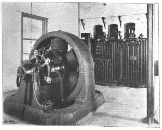
| Fig. 8 Interior of Garden Prairie Substation. |
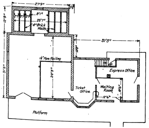
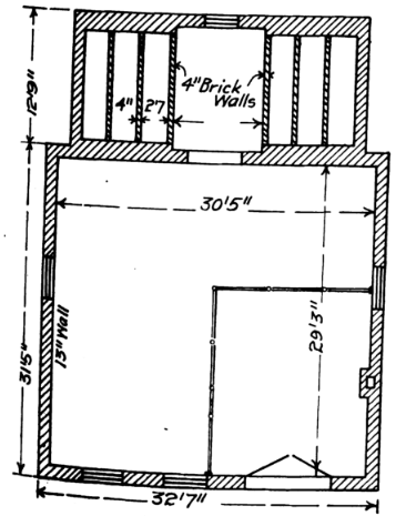
The three substations along the Elgin & Belvidere electric railway, as has been mentioned, are located at Gilberts, Union and Garden Prairie. The structures provided for this purpose are approximately similar, and the type of building may be seen in the illustration of the substation at Union, Fig. 7. The plan and elevation of the typical building are also shown in the illustrations. The substation at Gilberts, while in arrangement similar to the others, has some additional features in that apart of the building is two stories high and the main floor is materially enlarged. This building was in part remodeled from a structure already on the site. The substations are built of brick on concrete foundations, with concrete floors and roofs. The concrete floor is composed of one part of cement to three parts of sand and five parts of crushed stone, and it is laid upon 8 ins. of gravel and finished on top with one inch of top dressing. The roof is of cinder concrete, one part cement to three parts sand and five parts cinders, and it is water-proofed by hot pitch and three thicknesses of felt roofing.
 |
| Fig. 9 Plan of Substation at Gilbert's. |
With the exception of the Clintonville substation which is the property of the Aurora, Elgin & Chicago R. R., the equipment of the three substations is very much the same. It consists in every case of one 300 kw. 25 cycle, 3-phase, rotary converter, designed to receive the current at 370 volts alternating and deliver it at 600 volts direct current. The transformers are three in number at each station, of 110 kw. capacity, and they lower the current from 26,400 volts to 370 volts, 25 cycle. Included in each equipment is one oil-cooled reactance coil of 45 k. v. a. capacity. The switchboard equipment includes one outgoing panel, one direct-current rotary converter panel, two direct-current feeder panels , one direct-current voltmeter, one starting panel, and two lightning arrester equipments. The Clintonville substation in place of this equipment has in its switchboard but one out-going panel, carrying the necessary controlling switches and a polyphase induction recording wattmeter.
 |
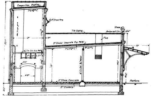
| Fig. 10 Plan of Typical Substation, Elgin & Belvidere Electric Road. |
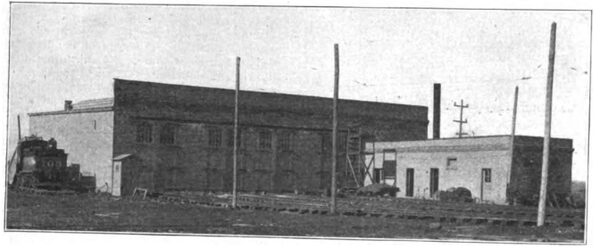
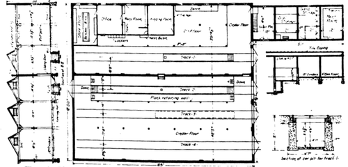
The car house and repair shop facilities of the road are combined in one building located a short distance west of Marengo. As now constructed the building is much smaller than the ultimate plans allow for. The accompanying illustration, Fig. 12, showing the track layout, gives the dimensions of the present building, 105 x 91 ft., and the size to which it will be extended when needed. In the illustration, Fig. 13, is shown a view of the exterior of the car house and the structure is shown in plan and sections in the illusration [sic] illustration, Fig. 14. The walls are of brick on concrete foundations. The interior framing and the roof are of wood, and a brick fire wall divides the principal structure into a north and a south bay. The south bay, shown below in the plan herewith, is used for car storage, inspection and general repairs . The north bay is divided into a number of rooms, the purposes of which are apparent from the illustration; and in the largest of these spaces is located the machine tool equipment. The winding room is set off by a fireproof partition of 4-in. tile. The boiler room, coal storage, sand storage and paint room given space in the small wing of the main building. The car house is lighted by four longitudinal saw tooth sky-lights; and arc and incandescent lamps generously placed furnish illumination by night.
 |
| Fig. 11 Section of Standard Substation of Elgin & Belvidere Electric Co. |
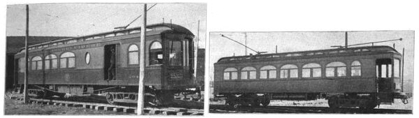
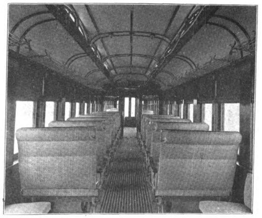
The initial rolling equipment of the road includes six passenger cars and two baggage and express cars, all built by the St. Louis Car Co. The passenger cars, one of which is illustrated in the accompanying views, Fig. 15, are arranged for single-ended operation and divided into a passenger compartment, and a smoking and baggage compartment. Both ends are vestibuled, and the passenger entrance is at the rear only. The toilet room is at the forward end of the passenger compartment. The heater is located in the smoking compartment. The motorman occupies an enclosed cab, fitted with a folding seat. The interior of the car is finished in dull mahogany with semi-empire ceilings of No. 14 sheet steel, decorated in green and gold. The smoking compartment is finished in light oak. High-back walk-over seats of the St. Louis Car Co., upholstered in rattan, are used. On the exterior the car is painted in green body with yellow panels. The length over bumpers is 47 ft. 1 in., and over vestibules 45 ft. 5 ins. The width over outside sheathing is 8 ft . 6. ins., and the hight [sic] height from the under side of sills to top of the roof is 9 ft. 4 ins. The truck centers are 26 ft.8 ins.
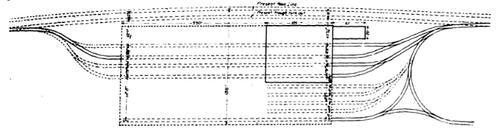 |
| Fig. 12 Present and Proposed Layout Car House Property at Marengo. |
The bottom framing includes side sills built up of a 5 x 8-in. and 5 x 6-in. yellow pine timber and a 1/2-in. by 6-in, steel plate, all bolted together. The two center sills and the two intermediate sills are 6-in. I-beams with yellow pine sills on each side bolted together, forming rectangular members into which the cross sills are framed. The end sills are 6 x 8-in. oak, reinforced with cross sills of 2 x 6-in. yellow pine framed between the longitudinal sills; 5/8-in tie rods extend along each cross sill and two needle beams of 6-in. I-beams fitted with truss rod struts are secured to the bottom frame. The truss rods are 14 ins. in diameter.
The auxiliary equipment of the car includes hot water heaters of the Peter Smith make, with No. 2 magazine coils, sectional parcel racks, pantasote curtains, the hand brake of the St. Louis Car Co. and Ohmer fare registers. The couplers are of the Van Dorn type No. 21 automatic, with No. 100 casing. The pilots are fixed to the trucks in such a position that they do not interfere with coupling two or more cars together. Arc headlights are used.
| |||
| Fig. 13 View of Elgin & Belvidere Car House at Marengo. |
The trucks are made by the Baldwin Locomotive Works, and the total weight is about 8000 lbs. each. The wheels are from the Standard Steel Works, and are of forged and rolled steel 34 1/2 ins. diameter. The flange is 7/8 ins. high, the tread is 3 ins. wide and the rim is 3 ins. thick. The wheelbase is 6 ft. 6 ins., and the axles 5 1/4 ins. The trucks are constructed of wrought iron frames with channel iron transom. The axles are of open-hearth steel and the journal boxes cast steel center, M. C. B. type. The minimum radius of curvature for which the trucks are designed is 45 ft., and the speed calculated upon is 50 miles per hour. The weight of the car body light is 30,-000 lbs. The maximum load is 14,000 lbs., making a total weight of 44,000 lbs., and the weight of the motors, of which four are carried, is 15,000 lbs. to the car. The motive equipment of the cars consists of four motors per car of 65 h. p. capacity, General Electric type, G. E. 74. Control equipment is the type M multiple unit for the purpose of allowing operation of the cars in trains when desired. Air brakes are provided.
 |
| Fig. 14 Plan and Section of Car House and Shop, Elgin & Belvidere Electric Co. |
The baggage and express cars are double-trucklike the passenger cars, but are designed for double ended operation. The length over bumpers is 45 ft., and the width over sheathing 8 ft. 6 ins. The hight [sic] height from under side of sills to top of roof is 9 ft. 4 ins., and the distance between truck centers is 26 ft. 8 ins. The trucks are different from those under the passenger cars, having 33-in. wheels and a wheel base of 6 ft. 6 ins. The axles are 54 ins. in diameter and the journals 44 x 8 ins. The maximum speed for which the trucks are designed is 30 miles per hour; and the minimum radius of curvature is 35 ft. These cars are heated by stoves. The couplers are the same as on the passenger cars, and pilots are also attached to the trucks.
| |||
| Fig. 15 Right-Hand and Left-Hand Views of Standard Interurban Passenger Car, Elgin & Belvidere Electric Co. |
The Elgin & Belvidere electric railway is now operating its cars on an hourly schedule between the two cities. The actual running time is about 1 hour and 45 minutes, the schedule allowing two hours for the trip. This time will be materially reduced as the roadbed and track are brought into better shape for high speeds. The fare between the two cities is 75 cents. The terminals at both Elgin and Belvidere are conveniently arranged for ready transfer to the connecting interurban lines, and schedules are arranged to give the best possible connection.
| |||
| Fig. 16 Interior of Elgin & Belvidere Passenger Car. |
The construction of the Elgin & Belvidere Electric railway as above described, was planned and executed by The Arnold Company, Chicago, engineers. Those in active charge for the company were George A. Damon, managing engineer; E. N. Lake, electrical engineer, George Weston, civil engineer, and W. H. Rosecrans, superintendent of construction. Officers of the Elgin & Belvidere Electric Co., are Hamilton Browne, president, and R. G. Arnold, secretary and treasurer. The road has offices in Marengo and also at 181 La Salle street, Chicago.
