[Trade Journal]
Publication: Street Railway Journal
New York, NY, United States
vol. 30, no. 15, p. 650-664, col. 1-2
SINGLE-PHASE ELECTRIC MOTIVE POWER ON THE
ROCHESTER DIVISION OF THE ERIE RAILRAOD
By W. N. SMITH.
One of the most important electric railway developments of the present year is the change from steam to electric motive power on a portion of the Rochester Division of the Erie Railroad, which took place on June 18, 1907. This is the first installation of a single-phase alternating system of electrical motive power upon a steam railroad, to go into commercial operation.
The Erie electrification can justly claim the priority of application of several important features which are of interest in connection with the discussion now prevailing upon systems best suited for steam railroad electrification. This line was the first in this country to operate electric cars on the single-phase system over the tracks of an operating steam railroad; the first in this country to use 11,000 volts working pressure commercially on a trolley, and the first instance of a single-phase traction system receiving power from a 60,000-volt transmission line.
| |||
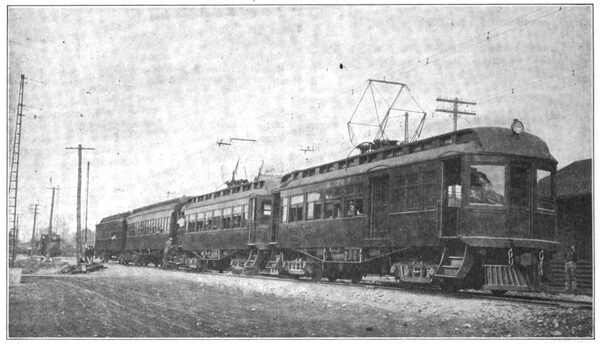
| Four-Car Electric Train on Erie Single-Phase Railway |
All of the construction described below, except that of the 60,000-volt power transmission line and the car bodies and trucks, was designed, executed and placed in operative condition by Westinghouse, Church, Kerr & Company, engineers, through whose courtesy the drawings and photographs were furnished which illustrate this article.
The section of track equipped is 34 miles long, extending from Rochester, over the main line of the Rochester Division, to Avon, a distance of about 19 miles, thence 15 miles over the Mt. Morris Branch. The railroad is entirely single-track, with sidings at way stations, averaging 3 to 4 miles apart. The grades are light, and the curvature for the most part quite easy, the line being relatively quite straight.
The track was originally laid with 68-lb. rails, but was relaid with 80-lb. rail, taken from another division just prior to the electrification. The road-bed is ballasted with gravel, and the joints are of the Weber type. A single No. 00 protected rail bond is applied to each rail joint under the plate, one of the advantages of the high-tension single phase system being that the relatively small current combined with the high impedance of the main circuit renders it unnecessary to resort to heavy bonding.
The line crosses a number of bridges, the longest one, that over the Genesee River, about 1 1/2 miles south of Rochester, being 780 ft. long and comprising seven spans. There are also through truss bridges at Rush, and at Caneserauga Creek, near Mt. Morris, and a stone arch bridge over Conesus Creek, a short distance south of Avon.
The electric service is devoted solely to passenger traffic, which is of the local interurban type. The freight service is handled exclusively by steam as heretofore, as are also the through trains operating between Rochester and Corning over the main line of the Rochester Division, a distance of about 94 miles. The steam service between Rochester and Mt. Morris originally comprised three round trips daily. The principal villages served are Avon, Geneseo and Mt. Morris, the other regular way stations being little else than cross-road stops. The population is entirely agricultural, and the Genesee Valley traversed by this line is probably one of the most beautiful and prosperous farming regions of New York State. Instead of three round trips per day, the electric service has introduced six complete round trips between Rochester and Mt. Morris, and three more between Avon and Mt. Morris.
POWER SUPPLY.
The power is generated at Niagara Falls, in the plant of the Ontario Power Company, and is transmitted at 60,000 volts, three-phase, over the lines of the Niagara, Lockport & Ontario Power Company, whose system has been fully described in former technical papers. The Iroquois Construction Company built a branch line from Mortimer, a little over 4 miles south of Rochester, to Avon, locating it upon the Erie Railroad right of way for nearly the whole distance. The pole. construction used upon this branch transmission line is the A-frame type, using two 40-ft. cypress poles, set abreast of each other, and inclined so that their tops are framed together, the butts being joined by horizontal plank braces underground. The cross-arms consist of two 3 1/2-in. x 6-in. timbers, 8 ft. long. The insulator pins are of cast steel, one being placed at the apex of the A-frame, and the other two bolted near the extremities of the cross-arms, so that there is an equilateral spacing of 7 ft. between each of the three wires. The insulator pins are grounded by copper wire. The neutral of the transmission system is grounded at the power station through a resistance. Lightning protection of the horn arrester type has been installed at every fifth pole. The conductors are of No. 4, hard-drawn, stranded copper cable. The standard length of span between poles is 220 ft., which is shortened at curves where necessary. When crossing over the tracks of the Erie, or other railroads, recourse is had to a special construction of No. 0 copper cables carried on steel towers, so reinforced by guys that it is impossible for a failure of the line to result in dropping the conductors across railroad tracks.
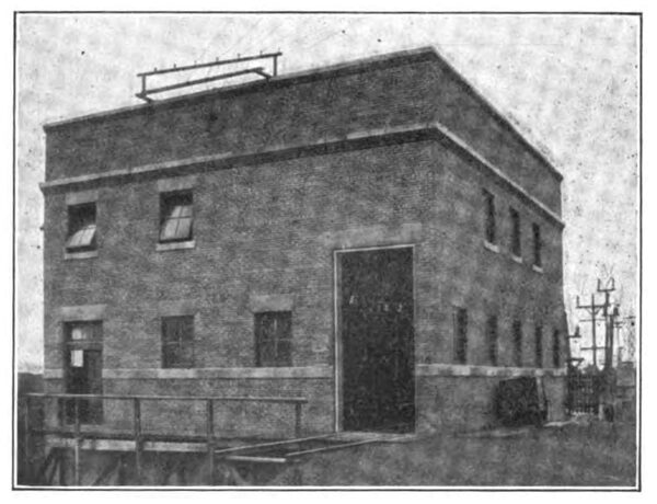
SUB-STATION BUILDING.
The sub-station building is located in the Y formed by the railroad tracks at Avon, and together with the car shed, is adjacent to the roundhouse and division repair shop. The walls of the building are of brick, resting upon solid concrete foundations, the roof and floors being of reinforced concrete. The floors are supported upon steel beams, but the roof beams are of reinforced concrete, like the slabs which they support.
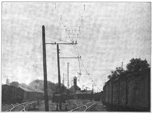
| |||
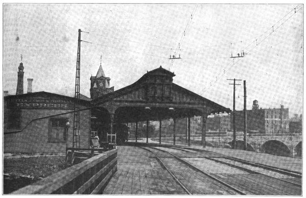
| Passenger Train Shed, Rochester Terminal, Showing Overhead Construction |
The building is absolutely fireproof, the doors and windows being of kalomein construction, and fitted with wire glass. The building is 39 ft. 8 ins. x 44 ft. on the outside and 29 ft. 10 ins. high from the top of the foundation to the top of the parapet. The door sills and lintels are of concrete blocks, and for architectural effect a belt of concrete blocks runs around the building, at the level of the window sills. The parapet is also topped off with a coping of concrete blocks.
In the basement of the building are located one of the transformer oil tanks and the oil pump. The main floor is divided into three rooms, the main transformer room being 43 ft. x 17 ft., and extending the full height of the structure to allow room for the high-tension bus-bars, which are carried over the transformers. The remaining space on the main floor is divided into a high-tension room (through which the 60,000-volt wires enter, and which is the location of the high-tension circuit breakers, 16 ft. 8 ins. x 19 ft. 8 ins.) and the operating room, which is 19 ft. 8 ins. x 24 ft., where all the 11,000-volt switching apparatus and the measuring instruments are located. Directly over the operating room is a mezzanine floor, reached by an iron staircase, in which are located the 11,000-volt lightning arresters, the 60,000-volt choke coils and the 60,000-volt series coils. The high-tension connections enter through the high-tension room, which runs from floor to roof and pass through the choke coils and series coil, on the mezzanine floor, and then turn through a wide opening in the wall to the 60,000-volt bus-bars, which are located in the upper portion of the transformer room.
There is space in the transformer room for another transformer of the same size and there is also space in the high-tension room for an oil-insulated circuit breaker should it ever be decided necessary. The interior is painted with cold-water paint of the same light green shade that is commonly used by the Erie Railroad for interior finish.
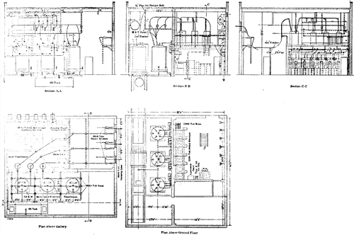 |
| Plans and Sections of the Avon Sub-Station |
The interior lighting equipment consists of forty-seven 16-cp incandescent lamps. Heat is supplied by a simple system of Colonial wall-type steam radiators, supplied by steam from the locomotive roundhouse.
SUB-STATION EQUIPMENT.
The transmission line terminates at the lightning arrester yard in the rear of the sub-station. The arrangement of the 60,000-volt lightning arresters consists of three horn gaps, arranged one behind the other, on each of the three conductors, the first gap being 4 3/4-ins. across, the second 5, and the third 6 ins. A concrete column is in series with the first gap, an electrolytic arrester in series with the second and a 5-ft. fuse of No. 18 copper wire in series with the third; that is to say, between one horn and the ground. Both horns of each gap are of 1/2-in. round iron. Between the line and the first arrester there is a hook-type knife switch, and between, the last arrester and the lead into the substation, there is a No. 18 copper wire fuse, in each conductor, placed horizontally upon the structure especially devised for it on top of a pole. These fuses are enclosed in wooden tubes about 5 ft. long, wrapped with torpedo twine. The entire arrangement of lightning arrester gaps, fuses and switches is mounted upon eighteen chestnut poles; and a suitable elevated platform, railed off and fitted with a gate to keep out trespassers, affords means of access to the apparatus when attention is required.
The three high-tension conductors enter the sub-station through glass discs held in 36-in. tile, set in the upper portion of the rear wall of the sub-station.
Within the sub-station, the wires first pass through three 60,000-volt stick-type circuit breakers, mounted directly inside of the rear wall. Thence, over bare copper conductors to the three oil-insulated choke coils, situated on the mezzanine floor, thence to three oil-insulated series transformers, also on the mezzanine floor, from which connections are taken to the power measuring instruments in the operating room. The main connections finally terminate upon a set of copper bus-bars in the transformer room, which are run upon porcelain insulators mounted on wooden cross-arms and placed at a convenient height directly over the line of transformers.
| |||
| Main Transformer Room in Avon Sub-Station |
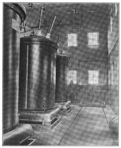
The 60,000-volt three-phase current is rendered available for single-phase distribution by means of three transformers of the Westinghouse oil-insulated water-cooled type, each of 750 kilowatts capacity. For the present installation, two transformers only are used at one time, the third being a spare. The high-tension connections are such that in case of one transformer failing while in service, its connections can quickly be taken off the bus-bars, and put on the spare transformers. The transformer windings are fitted with taps enabling the three-phase to two-phase "Scott connection" to be used. The low-tension windings can be so connected that either 11,000 volts or 22,000 volts can be obtained, so that in case it should ever be desired to transmit railway current for an extension of 40 or 50 miles, to another sub-station it could readily be done without adding transformers to this equipment. The low-tension windings also have six taps, enabling relatively small variations in the secondary voltage, if the same should be necessary to suit operating conditions in the trolley line.
One end of each low-tension winding is directly grounded to the boiler iron case, which in turn is, by means of a No. 0000 stranded copper cable, directly connected to the track return circuit.
| |||
| Avon Sub-Station |
The transformer cases are made of boiler iron, and set on a square cast iron base, which is in turn mounted on three pairs of wheels running upon an iron sub-base set in the concrete floor of the room. A track runs lengthwise of the room directly in front of the transformers, a transfer truck running upon it, upon the top of which there is another set of little wheels or rollers, which line up with those upon which the transformer cases are set. When it is desired to remove the windings from the transformer case, it is only necessary to disconnect the electrical, water and oil connections, roll the transformer off its sub-base, and onto the truck, which is then pushed to the rear end of the transformer room where it comes directly under a 10-ton hand hoist, which is able to lift any part of the transformer that repairs may make it necessary to handle.
Two cylindrical boiler-iron oil tanks are provided, each of slightly greater capacity than a single transformer. One is located in the basement directly under the transformer room, so that the oil from the transformer can readily be drained into it. The other is suspended from the concrete roof beams at the top of the transformer room, close to the side wall of the building, this being intended to act as a reservoir for distributing oil back into the transformer. The oil is pumped from the lower to the upper tank by means of a steam pump supplied from the boiler room in the adjacent division roundhouse, where steam is always available. From the upper tank oil is fed by gravity into either transformer. It is thus a simple matter to draw the oil off from any transformer if its insulating qualities are found to have depreciated, and the dehydrating, filtering or purifying apparatus can readily be employed with the aid of the pump, and the supply returned again to storage. The oil piping is of iron throughout.
The water circulation is by gravity, the supply coming from the railroad company's water tank system, at the adjacent round house, being pumped originally from the Genesee River about a mile distant. An artesian well had been opened up on the premises, but the water was so strongly impregnated with sulphur and other impurities that it was thought best not to introduce it into the copper piping in the transformers, although the cost of such a supply would have been practically nothing.
There are three separate water-cooled coils in each transformer case, each one controlled by its own valve, so that the amount of water may be controlled as found necessary under various conditions of load.
The necessary tranformation [sic] transformation from three-phase to two-phase, fits in very well with the natural subdivision of the electrified line into two sections, one of which is about nineteen miles in length, north of Avon, the other about fifteen miles in length, being to the south of Avon. The connections were therefore laid out to operate the sections upon separate phases of the two-phase secondary system. Either the T or V connection can be used, the latter method being employed at present. Each one of the active transformers therefore feeds a separate section.
As mentioned above, one terminal of each single-phase, 11,000-volt transformer is grounded. The middle transformer of the three is ordinarily used as a spare, and the other low-tension lead from this transformer runs to the center of a double-throw switch, whose outside poles connect separately to two low-tension bus-bars. The un-grounded low-tension terminals of the other two transformers connect through single-pole switches, one to each of these bus-bars.
The low-tension bus-bars run along the wall of the operating room, and directly beneath them are three type-E Westinghouse automatic oil circuit breakers, one on each of the two trolley feeders, the third breaker which is situated between the other two, being a spare. One pole of each of the three oil breakers is connected to the center pole of a double throw hook type switch, by means of which it is thrown upon either bus-bar. The other pole of the oil breaker runs directly to the feeder. The outgoing lead from the middle or spare circuit breaker can instantly be thrown upon either one of the feeders, should the breaker usually controlling that feeder be temporarily disabled. This system of connections is simple, compact and flexible, and has admirably fulfilled the conditions for which it is intended.
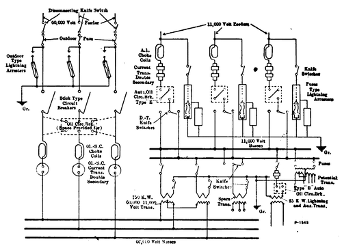 |
| Diagram of Connections, Avon Sub-Station |
The outgoing 11,000-volt feeders run up to the mezzanine floor directly over the operating room, where they emerge from the building through perforated glass discs, set in 18-inch round tiles. Before emerging there are tapped to them two Westinghouse low-equivalent lightning arresters, set in brick compartments, and reinforced by two electrolytic lightning arresters of the 11,000-volt type. A set of call bells is provided so that when the automatic breakers open a bell is rung in the car-inspection shed, adjoining. Also, if the temperature of any transformer runs above normal, a bell circuit connected to a thermometer in the top of the trasformer [sic] transformer tank is similarly made to operate. The station itself does not require the continuous presence of an attendant, which is needed in the case of a rotary converter sub-station. The working force is so organized that the car-repair men are always available for manipulating the sub-station circuit breakers, and the cost of attendance is thereby reduced to a minimum.
CATENARY TROLLEY CONSTRUCTION.
The overhead trolley construction is in many respects unique. It was the first of all catenary installations to operate regularly at 11,000 volts. There were very few precedents to follow; many of the details of the overhead work are entirely original, and nearly all of them were especially designed for this installation by the engineers who executed the work.
The poles are of chestnut, averaging 25 ins. in circumference at the top, and about 42 ins. at the butt. Most of them are about 35 ft. long, but 40-ft. poles were used where the embankments were narrow and steep, and in span construction. Nearly all the construction is of the bracket type, except at the railroad yards at Rochester, Avon and Mt. Morris, and for some distance at Mortimer, where there is a siding on each side of the main track, which prevented the use of bracket construction there.
The poles are given about 12 ins. rake. The poles are tamped with cobblestones, of which plenty were available from the coarse gravel with which the road is ballasted. The ground proved very deceptive as regards the nature of the digging, much water-bearing gravel and quicksand being encountered, and oil-barrels had to be resorted to in many instances, to prevent caving in of the holes during pole setting.
The brackets are of on entirely original design, each consisting of a 3 x 2 1/2-in. tee, 10 ft. long, the heel of which is fastened to the pole by a pair of bent straps, the outer end being supported from the pole-top by two 5/8-in. steel truss rods, instead of the single rod commonly used for bracket work. The two rods are attached about 27 ins. back from the outer end, and run one to each side of the pole, and are fastened there to a pole clamp devised for this work, which grips the top of the pole instead of requiring the bolt or truss rod to pass through it. In this way the timber of the pole is kept intact, and does not have a hole bored through it which will admit moisture and induce rot. The two truss rods are threaded at both ends, and at the upper end each one passes through a small iron casting which is in turn carried upon a bolt projecting out from the cast-iron portion of the pole clamp, like a trunion. The whole construction is extremely rigid, and is stronger and more conducive to a long life for the pole than any bracket hitherto used. Where necessary, at switches, extra long brackets are employed, being lengthened by splicing and an extra truss rod being attached by means of a clamp to the outer end of such a bracket, and run to the extreme top of the pole.
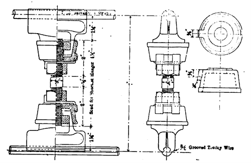 |
| Trolley Hanger Catenary Construction |
The insulator pins are of malleable iron, of a type specially devised for this work. The lower portion of the pin was divided and fitted closely over the flanges of the tee bracket, being provided with a single 5/8-in. bolt by means of which the lower split portion of the pin is clamped .securely against the bracket. The brackets and pins were furnished to the engineers' designs, by the Electric Service Supplies Company.
The insulator is of the R. Thomas & Sons manufacture, 6 7/8 ins. in diameter, and 6 ins. high, made in two parts, but of the three-petticoat type, and known as the No. 3029. It was designed by the engineers especially for this installation. As most of the overhead work was done during the winter months, and had to be rushed, a quick-setting cement of litharge and glycerine was used in place of Portland cement, which not only enabled rapid work in construction, but obviated troubles due to the freezing of hydraulic cement while setting.
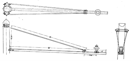 |
| Bracket for Catenary Trolley Construction |
The insulator pins are ordinarily about 12 ins. from the end of the bracket, but there is 27-1/2 ins. space between the end of the bracket and the point where the truss rods support it, which enables sufficient variation in location of insulator to meet most of the requirements in shifting the alignment of the trolley wire on curves.
 |
| Method of Grounding Bracket |
The messenger wire is of "extra high strength" steel, furnished by the American Steel & Wire Co. It is of seven strands and is 7/16 in. in diameter. Joints are made by using the so-called "open and "closed cable sockets, the sockets being sweated on to the abutting ends of the cables and joined by a pin connection through the eyes of the sockets. The trolley wire is No. 000 B & S grooved copper, the lengths being spliced with the usual type of soldered splicing sleeve.
The spans on the straight line track are 120 ft. in length, and as much shorter than this on curves as required by the radius of the curvature. The maximum deflection from the center line of the track, on curves, is 7 ins. each way. The catenary hangers were of the Electric Railway Equipment Co.'s drop-forged type, being modified by the engineers to suit the requirements. The messenger clip and the trolley clip are of the same type but grooved differently to accommodate their respective wires. They are joined by a 5/8-in. iron hanger-rod, with right-hand threads on each end, the longer rods being flattened in the middle to admit of bending them slightly, so as to conform to the divergence of the messenger and trolley wire near the ends of the spans. Both trolley and messenger ears are secured in position by jam nuts. This type of suspension was developed especially for this installation, and is so constructed that there is no possibility of parts coming loose and falling apart on account of vibration. It is also very quickly and easily adjustable on trolley wires. The hangers are spaced every 10 ft.
| |||
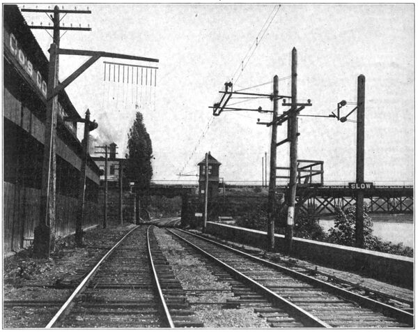
| Overhead Construction at Clarissa Street Bridge, Rochester, Showing Trolley Section Insulator, Bridge Warning and Block Signal Tower |
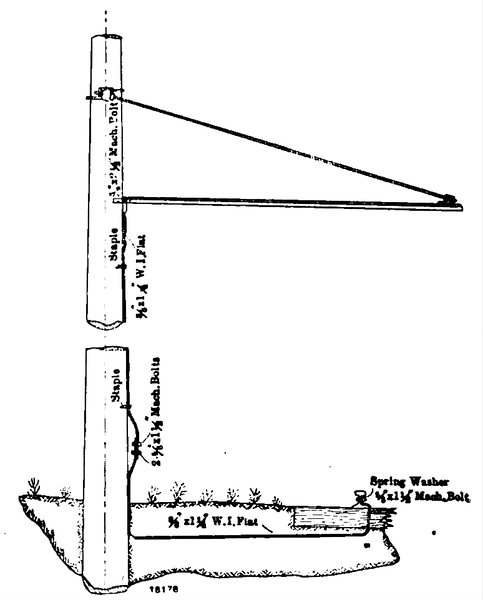
The steady strain rods are of treated wood of the Westinghouse Electric & Mfg. Companys make, and they are mounted at one side of the bracket instead of directly underneath, in order to give sufficient clearance for the paragraph trolley on curves, where the super-elevation results in the tilting of the shoe from the horizontal. Each steady strain rod is hinged to a spool type Thomas porcelain strain insulator, which is clamped to one side of the bracket in such a manner that the hinged end of the rod is almost at the elevation of the top of the tee bracket. The method of attaching the steady strain insulators to the bracket is such that they can readily be shifted along the bracket to follow up any change in alignment of the trolley wire that may be required by curvature or for any other reason. The clamps holding the steady strain insulators are of 3 in. x 3/8 in. bent iron. The spool type insulators are cemented on to pieces of 3/4-in. pipe, through which passes the 5/8-in. eye-bolt by means of which they are attached to the bent irons. Steady strains are used only on curves and turnouts and were not found necessary on tangent track.
The tie wires are of No. 9 Extra BB, galvanized telegraph wire, because it was thought best not to make too rigid an attachment between the messenger wire and the insulator; so that if a bracket became detached from the pole for any reason, its weight and the shock of detachment would tear the wire clear from the messenger and allow the bracket to fall entirely away from the wire and reduce the chance of steam railroad trains colliding with it. An accident to the electrical equipment of a railway operating both steam and electric trains, may shut down the electric service, but will not automatically place any check upon the steam service, so that accidents to steam trains must be guarded against, as a steam train might easily be wrecked by an obstruction which would automatically prevent power from being supplied to an electric train. This was one of the reasons for installing the system of "ground rods" from the brackets to the rails, which is carried out very consistently throughout the installation. Every bracket is grounded to the rail, so that an insulator failure will instantly throw off the power, as it will cause a complete metallic short-circuit. There is thus no danger of setting the wooden poles on fire, which would be possible if this precaution were not taken. The burning of a wooden pole would not of itself necessarily cripple the electric service, but it would be quite likely to cause an obstruction dangerous to the passage of steam trains which are, of course, independent of any disturbances on the electric motive-power system. Up to the present time, however, there have been no cases where the overhead construction has caused any obstruction to the passage of the steam traffic.
 |
| Detail of Deflector for Catenary Construction |
The ground rods consist of 3/8 in. x 1 1/4 in. flat steel, their upper and lower ends being bolted to track rail and bracket respectively.
The span construction is as nearly as possible similar to the bracket construction, and uses the same type of pin and insulator. A piece of 3 in. x 2 l/2 in. tee about 30 ins. long is suspended from the span wire by hangers of galvanized strand cable, adjustable in length, and fastened to the span wire cable by specially designed clips, the construction forming a sort of stirrup upon which the pin and insulator are carried. The messenger wire rests upon the insulator just as in the case of regular bracket construction. This form is used, not only for spans where there is but one track, but also in the yards at Avon, and Rochester, where three or four parallel tracks are electrified. Span construction, in general, was only used where conditions absolutely required it.
| |||
| Overhead Construction, Mt. Morris Terminal |
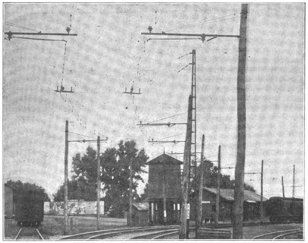
The Rochester yard was a difficult piece of construction on account of the distance between supports (which reaches a maximum of 94 ft., where spanning seven tracks, four of which are electrified), and also on account of the uncertain nature of the soil which on the river bank is filled in with gravel and cinders. For these long spans, where it was impossible to use guys of the usual type (the river bank being on one side and the main highway which gives teams access for loading and unloading of freight cars on the other side), it became necessary to use self-supporting span construction, and this was done by using the "Tripartite" type of steel pole, set in Concrete. This type of pole being constructed of re-rolled Bessemer steel rails, is less subject to rust, and consequently more durable than any other available type of metal pole, and all of its surfaces are always open and easy of inspection. On account of the great tensile strength of the material, there is considerable saving in weight, and the fact that it was a standardized product, enabled quicker delivery to be made than though special riveted poles of structural steel shapes had been especially designed for these locations. The span wires consist of the regular messenger cable fitted with cable sockets sweated on at each end. the same being fastened to turnbuckles and pole collars at the tops of the poles. There are two span cables at each pair of poles, the upper one being used to carry the weight, the lower one acting to steady the arrangement and also to act as a relay in case of an accident to the upper span. Similar construction was also used at Avon, where guying of side poles was not always possible.
A very simple type of pull-off was devised for curves in span construction, and it so happens that both the Rochester and Mt. Morris yards have considerable curvature. The pull-off consists simply of a spool-type insulator, with a piece of pipe cemented through the center, this pipe being slipped over the hanger spacing-rod joining the messenger and trolley clips, thus giving an insulating connection through which an ordinary pull-off cable can be attached to both messenger and trolley wherever required. The division of the horizontal pull between the messenger and trolley, wires is easily adjusted to suit the conditions, by shifting the spool-type insulator up and down the spacing rod, by inserting longer or shorter nipples of pipe underneath it. In general, when near a span wire, the messenger cable is supported rigidly on its insulator and the trolley wire needs all the side pull; but in the middle of a span the pull must be equally divided between messenger and trolley wire.
The presence of several through-truss bridges over streams and two low bridges over the Erie right of way necessitated the employment of special construction at these points, particularly at the bridge at Clarissa Street, on the outskirts of Rochester. The original clearances here were so low that the road-bed had to be excavated out and the track lowered about 2 ft., and the minimum clearance between the rails and the trolley wire being finally 18 ft. The messenger is fastened to a horizontal stool-type insulator mounted at the center of a substatial [sic] substantial piece of turned oak, which is long enough to carry two more similar insulators, one on either side of the center one.
| |||
| Avon Yard, Looking South Toward Station |
The steel hangers reaching down from the overhead bridge structure carry the two side insulators, so there are always two insulators in series between the 11,000-volt messenger cable and the steel work of the bridge. These insulated supports are suspended at short intervals from the under side of the steel-work of the bridge, and are further supplemented by the use of steady strains which prevent any side displacement of the trolley wire. The shortest sizes of hanger spacing rods are used in such places. Where the bridge trusses are high enough to permit it an iron stirrup is employed like that used in span work, which carries the standard form of straight line insulator, and the regular type of catenary suspension is employed.
At either side of these overhead obstructions it was necessary to provide warnings for brakemen upon the tops of freight cars, as substitutes for the warnings of hanging pieces of rope previously used. In the accompanying cut on page 657 is given a view of the Clarissa Street bridge, showing both the old arrangement of ropes and the new one, for electrified tracks, which supplanted it. It will be noted at this point only one of the two tracks is electrified and freight trains are here obliged by rule to use the unelectrified track; but to insure that the place shall be absolutely safeguarded, the electrified track is fitted with warning signs of the type shown. They consist of the well-known type of horizontal, suspended swinging wooden rod, mounted with its axis at an angle, so that it swings up as it is pushed to one side. The pantograph trolley is fitted with a set of springs on each side, one of which strikes this warning sign a blow as it passes under and instantly throws it to one side. The blow is struck upon a heavy leather strap held taut by a coil spring of steel wire in tension, the whole contrivance being fastened to the lower half of the pantograph trolley mechanism so that it is at the right height for striking the warning sign. The swinging rod is mounted upon the pole by means of insulators, effectually preventing any leakage to the ground, even though a car might stand still directly under the sign and make contact with it for an indefinite length of time.
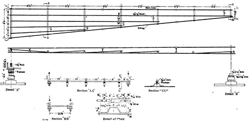
Nearly all the telephone and telegraph wires which cross over the 11,000-volt trolley wire have been put underground, particularly in the case of the leads composed of only a few wires, but where the line is crossed by heavy telephone trunk lines, they have been protected by the basket type of construction, so designed as to effectually prevent a broken telephone wire from falling across the messenger or trolley wire. This consists primarily of four galvanized steel cables stretched between opposite ends of two cross arms, one placed above and the other below the wires of the intersecting telephone line, and the four cables are joined by a basket-work of light strap-iron ribs placed at intervals of 3 to 4 feet across the whole span, forming the sides and the bottom of the cradle and effectually preventing a broken telephone wire from dropping any further. This construction was also followed in the case of an electric light line at Avon.
The telegraph department of the railroad company, in connection with the signal department, constructed a private telephone line of two copper wires between Rochester and Avon, with instruments at all signal towers and stations in the dispatcher's office, and at the sub-stations, and car shed, and master mechanic's office. This telephone system is run upon the trolley bracket poles, transposed every third pole, and has worked satisfactorily.
Lightning protection for high tension single-phase railway lines not having as yet been standardized, only a part of the line was equipped with line lightning arresters, which are of a swinging fuse gap type of construction, made by the Westinghouse Electric & Manufacturing Company. This type of lightning arrester consists of a gap one side of which is connected directly to the trolley through a No. 4 copper wire, and the other side being directly connected to the ground rod through a fuse enclosed in a tube which, while the fuse is intact, is maintained in an inclined position like a pendulum held back from its position of rest; but when the fuse is blown, a latch is released which allows the fuse tube to swing to a vertical position which shows conspicuously from the ground, and signifies to the patrolman that the fuse should be replaced. The fuse tube can then be lifted off the suspending lugs by a pair of insulating tongs made for the purpose, and the fuse renewed and replaced in a few moments.
On the other half of the line, lightning arresters were not installed. During the summer, two of the poles were struck by lightning, but the metal-work of the brackets and truss rods being entirely grounded, these poles were not damaged below the topmost point of attachment of the truss rods, which is generally not over 18 ins. from the top of the pole. In a number of instances the lightning-arrester fuses have blown, but it is not known how many of them have blown simultaneously. Although the extent to which this type of arrester is fully protective, is hardly established as yet, it can be stated that at no time since regular operation started, has any injury to the car equipment resulted from lightning, though there were several severe storms during June and July.
The trolley line is divided into seven sections one comprising the Rochester terminal, one of the Avon yard, three sections in the main line between Rochester and Avon, and two sections south of Avon.
The sections are divided by trolley section insulators, made by the Westinghouse Electric & Manufacturing Company. They are of the overlapping type, made of impregnated wood, and are of sufficient length to insure insulation at 11,000 volts. Each section insulator is carried upon two brackets, mounted on poles spaced 10 ft. apart. As the trolley and messenger must both be completely insulated on opposite sides of the breaker, heavy strain insulators are introduced upon which the messenger is dead ended, the two insulators being connected across the gap by a heavy steel rod. This entire combination is supported upon standard insulators mounted upon the regular brackets.
One of the breakers, that opposite the sub-station at Avon, is different from the above-mentioned type, in that it is not of the overlapping type, it being necessary to absolutely separate the two halves of the trolley line in order to utilize the separate phases of the trolley current in each half
The only feeders necessary are those connecting the substation with the trolley on opposite sides of this section break. The principal object of cutting the trolley into additional sections is to facilitate the locating of line trouble.
The conditions of electric traction upon this line are such that no feeder is necessary besides the trolley wire, and consequently there is no necessity for feeding the sections separately. A jumper is therefore provided at each section insulator in which is placed a hook-type knife switch that can be operated in case it is desired to cut that section out. Normally, however, the switches are closed and the effect of the jumpers is to make the trolley wire continuous.
Another detail peculiar to the catenary type of trolley construction is the "deflector" a sort of mechanical fender placed in the angle formed by the intersecting trolley wires at switches. The type of deflector here used consists of four or five bars of flat steel, 1/2 x 1/4, suspended by riveted hangers, from crossbars spaced five feet apart which in turn rest on standard trolley clamps fastened to the trolley wire. The particular advantage gained by this construction is that no extra tension is needed to keep the bars from sagging and getting crooked, this type of deflector being of minimum weight and entirely self-contained. They are placed in both angles of each switch. The object of the deflector is to prevent the end of the pantograph shoe, when traveling under either wire from becoming hooked over the other.
CARS.
The cars equipped with electric apparatus are six in number, and together with their trucks were furnished by the St. Louis Car Company. The electrical apparatus was installed upon the cars and trucks by the engineers at the railroad companys car shops in Buffalo, N. Y. The cars are 51 ft. 4 ins. over bumpers, 40 ft. over corner posts, and 29 ft. 4 ins. betwen [sic] between truck centers. They are 8 ft. 9 ins. wide over sheathing, and 13 ft. ins. in height above the rail. Four of the six have two passenger compartments, the other two having a baggage compartment about 14 ft long, and a small smoking compartment with six seats, besides the regular passenger compartment.
The bottom construction of the cars comprises side sills of 5 x 8 yellow pine, with 6-in. steel channel and fillers, intermediate sills of 4 1/2 x 6 yellow pine, and center sills of 6-in. I-beams, with fillers. All the cars have upper and lower truss rods and needle beams of 5-in. I-beams. End sills are 8 x 6 in. oak. The flooring is double, and trap doors are fitted over the motors.
All the lower side windows are equipped with sash balances, and the interior of the car is finished in mahogany with light green veneering in the ceiling, of a very pleasing appearance. The seats are of the Walkover" type, upholstered in dark green plush in the main passenger compartment, and in rattan in the smoking compartment. There is a continuous basket rack on either side over the windows. The end doors are of the double sliding type. The vestibule doors are of the single sliding type, and trap doors are fitted over the steps. Each vestibule is fitted with a double-acting swinging door so arranged as to form the motormans cab, and when not so used it is folded back to completely enclose the control apparatus and brake gear, and leaves the vestibule unobstructed for passengers.
Each car is fitted with a 50-cp headlight, at each end, on top of the hood, and it is also fitted with a gong, air whistle and with the standard train air signal used by the Erie Railroad. The toilet is in the center of the car, adjacent to the partition between the compartments. The Standard" steel type of platform buffer is used, and the regular M. C. B. coupling, air hose connections and safety chains are provided, so that the cars can couple up to any of the standard Erie Railroad rolling equipment.
There being an open space between the abutting vestibules when two motor cars are coupled together, due to the rounded and projecting buffer beams of the platforms, this opening being nearly 18 ins. in width, which is wide enough to allow a person to fall between the cars, there were provided canvas curtains about 5 ft. high with snaps attached which enable them to be quickly stretched across the space, one on each side of the vestibule end door, so as to insure the safety of trainmen and passengers when walking from one car to another, with the train in motion.
The trucks are both alike, wheel base being 6 ft. 8 ins. The axles are 6 1/2 ins. diameter. The trucks are of the standard M. C. B. swing bolster type, with heavy framing. The brake shoes are inside hung.
The heating equipment consists of thirty-two of the Consolidated Car Heating Company's electric heaters of the truss plank type and 450 watts capacity each in the main portion of the car, and two No. 192 M. S. heaters in each cab.
ELECTRICAL EQUIPMENT.
The electrical equipment of the cars consists of four No. 132-A Westinghouse single-phase railway motors, with nominal rating of 100 hp each, the gear ratio being 20.63. The suspension is of the nose type, and solid gears are pressed upon the axles.
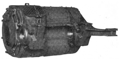 |
| 132-A Single-Phase Motor Used on the Rochester Branch |
The control system is of the Westinghouse electro-pneumatic type, and includes three distinct circuits, the high potential, the low potential and the control circuit.
The high potential circuit includes the pantograph trolley, line switch and the transformer. The pantograph trolley mechanism is operated by a pair of springs and by an air cylinder. The trolley is raised and held against the wire by means of springs against its own weight, and it is lowered by the application of air pressure to pistons working in cylinders that form part of its base. When down, it is automatically locked, and the latch of this lock can only be withdrawn by applying air pressure to another small piston which then unlocks the pantograph, allowing the springs to raise it. This trolley mechanism is so connected with the control circuit through the line relay that any interruption in the supply of high-tension current immediately causes the trolley to be lowered by applying the air to the main clinders [sic] cylinders in the trolley base.
The line switch is equivalent to a main high-tension circuit breaker. It is opened and closed by air pressure, admitted by electrically operated valves. In case the supply of air is exhausted, as when the car has stood for some time unused, the line switch must first be held in mechanically by means of a handle provided for the purpose until the air pump, which can then be thrown into operation, has compressed air to about 50 lbs. pressure, which is enough to properly actuate the control system.
To raise the trolley when there is no air pressure available, there is provided a small automobile tire pump. This pump is placed underneath one of the car seats, and is connected by a three-way cock into the trolley air piping system. It enables the air-operated trolley latch to be withdrawn and power to be obtained to start the air compressor and set going the motor generator set used for charging the storage battery and supplying current to the control circuit.
The transformer is of 200 kw capacity, and is of the oil insulated type. It has three high potential and eight low potential taps, the latter running from 300 down to 110 volts, at which latter pressure current is provided for heating, lighting and auxiliary purposes.
The high-tension wiring of the car is done mainly with varnished cambric cable, drawn through loricated iron conduit. A small amount of high-grade rubber cable is used, but it is thoroughly protected with varnished cambric tape wherever there is danger of a brush discharge to ground breaking down the insulation.
In the main low-potential circuit are the switch group, the preventive coils and the reverser. The switch group is a set of air-operated switches controlled by magnet valves, all mounted in one frame. It is placed athwart the car as near as possible to the low-tension end of the main transformer. The switches of the group are all provided with interlocks, which automatically govern the connections in such a way that each switch of the group acts only when the current in the motors has reached a predetermined value, thus making acceleration automatic. Preventive coils are used across the terminals of some of the switches of the group, to prevent excessive current flowing at the instant of closing the switch. Each switch in the group is fitted with its own blow-out coil. There are two reverser switches actuated by air pressure, one for each pair of motors.
Current from the main motor circuit is led through the motor limit switch, which makes effective the functions of the interlocks on the switch group, and renders it impossible for the successive switches to be thrown in unless the limit switch is closed.
The control circuit includes a master controller in each vestibule, the train line wires and their connections to the valve magnets and interlocks, a storage battery supplying current for these wires, and a motor generator set, which is used either to charge the batteries or to actuate the control system. The master controller makes the proper connections by means of which the 15-volt storage battery actuates the valve magnets which control the action of the air-operating main contactors in the switch group, and the reversers. The controller handle is normally held in a vertical central position by springs, unless it is moved to one of the running points by the motorman. When released from the grasp of the hand it flies to the vertical position, cutting off the power, and enabling the emergency application of the brakes by means of brake relay valve alongside of it. There are two holes in the face of the master controller, directly under the handle, and attached to the handle by means of a chain is a plug which may be inserted into either of these holes. The master controller is not operative unless this plug is pushed all the way into the lower hole, which closes the line switch, connects the generator and battery, and puts the brake relay valve into circuit. This is the ordinary running position of the plug. In case the line switch is opened by an overload, which generally causes the trolley to be lowered, the plug is taken out of the lower hole and placed in the upper, which action immediately closes the line switch, releases the trolley, and allows it to spring up against the wire. As soon as the power is thereby returned to the main circuit, the plug is taken out of the upper hole and replaced in the lower one.
There is a push button upon each side of the bottom of the master controller case. That on the right hand side is used for dropping the trolley and opening the line switch. When the button on the left hand side is pressed the switch group is stepped up to the last or high speed notch and remains in that position until the handle of the controller has been returned to the off position.
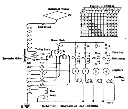 |
| Schematic Diagram of Car Circuits |
There are four distinct notches on each side of the controller, the first corresponding to the coasting position with the power off, the others enabling such gradations of speed as may be desired. Reversal is effected by moving the controller handle to the opposite side of the center or dead point. If the controller stops on the dead point, as it will if released by the hand, it will immediately apply the brakes.
The motor generator set is a compact machine of about 1/6 kw, the motor being of the self starting induction type, wound for no volts, the generator being normally of about twenty-three volts. It is placed under one of the seats in the car and. is covered by a box with removable lid, so that it can easily be reached for such small attention as it requires. It is mounted upon rubber bushings, and runs so quietly that its presence in the car can hardly be detected.
The storage battery consists of seven cells contained in a wooden box with handles, carried in an enclosed box underneath the car. No other auxiliary lines for any purpose are connected to the control circuit in order to prevent it from being disabled by accidental grounds.
In one vestibule there is located in an asbestos lined compartment enclosed with steel doors a slate switchboard panel upon which are carried all the switches and fuses for the control of the battery and motor generator set, the lighting circuits and heaters, and also the main connection from the low tension side of the transformer to the auxiliaries.
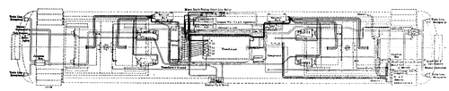 |
| General Arrangement of Wiring and Electrical Apparatus |
The control circuit is fitted with junction boxes, branches running to receptacles at each of the four corners of the car directly under the end sills. The jumpers for connecting the cars and the receptacles are of the 12-point type, there being twelve wires in the main control circuit.
The low tension wiring between the transformer and switch group and motors is all enclosed in a boxing of "Transite," to insure its protection against mechanical injury, as the inductive effect of heavy currents at low potentials renders the use of iron conduits impossible for this part of the wiring.
The air brake and electrical equipment a were placed upon the cars by the engineers at the Buffalo car shops of the Erie Railroad.
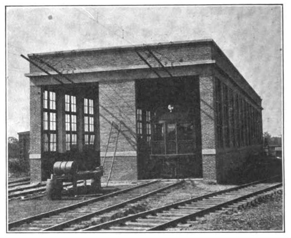
CAR INSPECTION SHED
Adjacent to the sub-station is a car inspection shed, a brick building that will accommodate four cars. It is 136 ft. 6 ins. long, 30 ft. 5 ins. wide and 20 ft. high in the clear, between the track and the bottom of the roof girders, and 24 ft. high from the top of foundation to the top of the parapet. The general style of construction is similar to that of the sub-station. It is remarkably well lighted, there being a window in each bay 6 ft. 11 ins. wide by 13 ft. 6 1/2ins. high. Two tracks run clear through the building, the ends of which are enclosed by rolling steel doors of the Wilson type, about 12 ft. wide and 18 ft. 9 ins. high. One of the two tracks is provided with a pit about 110 ft. long and 4 ft. 4 ins. wide, in the clear, and 3 ft. deep from the top of the rail to the top of the convex brick floor.
The foundations consist of concrete piers, joined by heavy reinforced concrete lintels upon which the brick walls rest between the piers. The building is located on filled-in ground, and the piers reach down to a reasonable distance below the level of the original natural soil. The space around the building and between piers and underneath the floor and pit of the building is filled in with gravel and cinders.
The roof is a 4 1/4-in. reinforced concrete slab, supported by steel girders, slightly pitched in one direction. There are no partitions or separate rooms in the building.
A trolley hoist is provided at the rear end of the building, traveling across it on the bottom flanges of an I-beam attached to one of the roof girders. A third track, not connected with the outside tracks, runs up and down the middle of the building between the two car tracks. A transfer table is located in a cross pit situated about midway of the building, by means of which a car standing on the floor track may have a truck taken out from under it and shifted over to the center track, on which it can be run under the trolley hoist in case repairs are needed. The sides and bottom of this transfer pit are made of concrete.
The floor of the car barn, other than that taken up by the repair pit and transfer pit, is paved with second-grade paving brick, laid on sand, which was well packed down with water.
The station is supplied with light by means of seventy-seven incandescent lamps in pairs and clusters, connected up by a conduit system and steel plate switch cabinet to the auxiliary light transformer in the sub-station.
The pit is also provided with ten incandescent lamp outlets and extension plugs. No electrical means are provided for moving the cars in the station, there being always steam locomotives available for shifting the cars in and out of the building.
The inspection shed is, like the sub-station, heated by steam. The radiators are of the Colonial wall type, one being set in each bay and fed by a steam pipe passing underground through a concrete pipe trench, which also carries the compressed air piping. The latter is supplied from a steam air compressor outfit in the division repair shop. The main steam supply header runs overhead directly above the windows, and the condensed steam waste is discharged into the open air. A 4-inch water line runs completely through the building, and there is one 2 1/2-in. hydrant at each end just inside of the door and a third.in the center of the building.
| |||
| Car Inspection Shed |
The above facilities for effecting electrical repairs are supplemented by the regular division repair shops, located alongside the steam locomotive roundhouse at Avon, which are equipped with the usual complement of machine tools. At the Rochester terminal a concrete inspection pit 60 ft. long is provided on one of the side tracks close to the passenger station.
OPERATION
The equipments above described were intended to be sufficient for operating single car trains with one stop per mile over the entire road, at an average schedule speed of twenty-four miles per hour, or to haul one trailer making stops about two and one-half miles apart at the same schedule speed. The company has furnished shelters where the public highways cross the line, there being twenty-two of these flag stations besides the regular intermediate way stations at which steam trains stop, six in all, or a total of twenty-eight stations at which electric cars may be required to stop. Practically the electric cars stop at all the regular way stations, but at only a portion of the flag stations. A single passenger coach is frequently attached to a motor car, and on some trains baggage, milk or postal cars are regularly hauled. When two trailers are hauled two motor cars are required, making a four-car train, as shown in the attached photograph. The service has proved immensely popular throughout the Genesee Valley through which it passes, and it is intended to increase the number of motor cars in order to handle the business a little more comfortably next season. It is found that the electric trains on their thirty-four miles of line can be depended on to keep to their running time rather better than the steam passenger and freight trains operating over the main line.
SIGNAL SYSTEM
The railroad company has installed a positive block system for insuring the safety of trains with the frequent headway at which they are obliged to be run upon the single-track road, which must also handle steam passenger and freight traffic at the same time. The blocks extend between the regular way stations, or if such blocks are too long, switch towers are added, making the blocks average about four miles in length from one end of the line to the other. Without going into detail it may be stated that the function of the positive block system is to absolutely prevent more than one train at a time from occupying a block. The sidings are fitted with interlocking switches controlled by the block operators in the towers or in the way stations, and the movement of trains is thus regulated with the greatest care. The towers are all connected by the private telephone line, while the way stations retain the usual telegraphic communication with the train despatched office at Rochester. By means of the telephone communication it is instantly possible for a train crew to get in touch with the chief despatcher and be properly located, but all train orders are transmitted by telegraph and written out on Form 31, as is the uniform steam railroad practice throughout the country.
TELEGRAPH SYSTEM
As is well known, the single-phase trolley system causes interference with telegraph lines along the right of way, and unless both the electrostatic and electromagnetic induction are properly compensated there is always danger of telegraphic communication being seriously affected. The static effect is particularly annoying, as it is absolutely continuous as long as the trolley line is charged, whether or not there are any cars moving. Various means were proposed and tried by the Western Union Telegraph Company for the elimination of the static, which always causes the telegraphic relays to chatter, but the most successful thus far known is that due to the inventive genius of E. W. Applegate, quadruplex expert for the Western Union Telegraph Company, who has developed a very simple means for overcoming static interference. Mr. Applegate worked upon the theory that it was useless to try to compensate for the static, and that the thing to do was to "pacify" the instrument by additional devices. The Applegate "static pickup," for which a patent has been applied, comprises a back contact relay and a high resistance shunt. The current enters the relay 1 and 2 through a 150-ohm coil or magnet, attracting the armature C. When the line opens by any operator opening his key the armature C falls back and through the back contact connects points C and D by the aid of a spring 5.
The shunt A consists of 350 ohms of carbon stick, and provides a better path for the static than do the magnets, pacifying the magnets to a certain extent. When the line opens and the armature connects with the back stop C and D, both the A and B shunts are in with the main line and pick up the static which escapes through shunt A, relieving the agitation of the armature so that it can respond to the closing of the line.
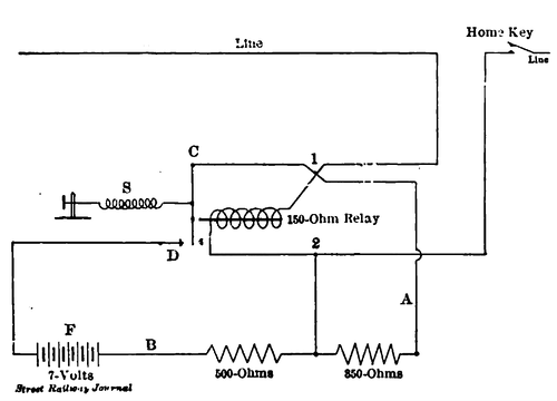 |
| Diagram of Static Pickup for Telegraph Relay |
The shunt A robs the relay of main line battery current very materially, so that it responds to the home key sluggishly. Consequently the auxiliary battery F is inserted in shunt 2. When the armature C falls back this battery acts upon the magnets and assists their prompt response to the home key or to any other operator to such an extent that the shunt A does not cause noticeable drag. No matter what the line static may be these shunts "pacify" the instruments and the static is not felt.
The armature spring is adjusted high enough to overcome the wave of static that escapes A and B shunts. The aid of the 7-volt battery overcomes this adjustment and leaves the relay very prompt and satisfactory.
The resistance of the shunt A must be determined by the distance from the ground and battery at each end of the line. The nearer to the ground the less is the resistance of the shunt, as in close proximity to battery and ground the static is more pronounced and the effect of the main battery upon the relay is likely to be correspondingly diminished.
By this arrangement all the telegraph wires are "singled," and metallic circuits, the necessity for which was at one time pending, were discontinued, and the repeater service which they necessitated was also discontinued, and there is now a spare wire between Rochester and Mt. Morris through the entire zone of static interruption.
Speech over the telephone line is very clear and distinct, and although the wires and instruments have a heavy static charge, a few simple precautions enable it to be of great use to the operating department. It is intended to carry portable telephones upon the cars.
ORGANIZATION
The single-phase system was recommended for the electrification of this division by the Electric Traction Commission of the Erie Railroad, and after authorization by the company was installed under the general direction of J. M. Graham, vice-president and head of the construction department of the Erie.
The engineering and the construction work were carried out and the system brought into operative condition by Westinghouse, Church, Kerr & Company, who designed and erected the buildings and the catenary trolley construction, bonded the track and installed the electrical apparatus in the substation and on the cars.
| |||
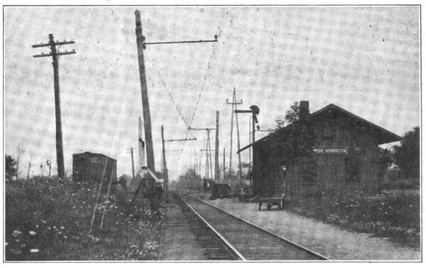
| Overhead Bracket Construction Main Line and Siding at West Henrietta Station |
The The adjustment of the telegraph system was carried out jointly by the Western Union Telegraph Company and the telegraph department of the railroad company.
The order was given to the engineers on June 6, 1906, and although the intense activity in construction work all over the country at that time rendered it difficult to secure materials and labor promptly, the work was pushed so rapidly that about seven and one-half months later, on Jan. 22, 1907, the first official trial trip was run between Avon and Rochester. The severe winter weather thereafter prevailing delayed the completion of the work until spring. During April and May the whole equipment of sub-station apparatus, lines and cars was thoroughly tried out in a course of experimental operation, which also enabled the railroad employees to become familiar with the new system. On June 18 commercial operation began and has since continued permanently with marked success.
The Erie is one of the oldest steam railroads in the country, but that it is also one of the most progressive is demonstrated by its policy of giving a thorough trial to a system of electric traction whose characteristics of simplicity in construction and economy in operation make it so eminently fitted to replace steam motive power wherever the economic conditions point to the desirability of its substitution, for the betterment of either passenger or freight service.
