[Trade Journal]
Publication: The Railway Times
London, England
vol. 95, no. 23, p. 557-559, col. 1-2
A NOTABLE SINGLE-PHASE AMERICAN RAILWAY FROM
CHICAGO TO SOUTH BEND.
Compared with the absence of enterprise in this country in the application of electricity to railway work, progress in the United States is astonishing. It is particularly noteworthy in the direction of transport between closely adjacent towns. Concessions for the construction of what are termed interurban lines are obtained with great readiness, and there is an almost unimaginable absence of State and municipal trammels in the construction of these lines. A typical instance is afforded by the new electric line which has recently been constructed from Pullman (celebrated as the seat of the chief manufactory of the Pullman Palace Car Company), where it connects with the Illinois Central Railway, round the southern end of Lake Michigan to South Bend, a distance of about 77 miles. The railway runs through the streets in the cities, and crosses a large number of roads in the country. As showing the general excellence of the service, it may be mentioned that while the limited trains between Pullman and South Bend make the run of 77 miles in 2 hours and 15 minutes, the journey by the Illinois Central suburban express train from Randolph Street ,Chicago, to Pullman, a distance of 15 miles, requires 45 minutes. The limited trains make stops at only six towns in the 77 miles, but the local trains stop on signal at all highway crossings in the country and at all city street crossings.
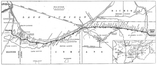 |
| Map of Single-Phase Electric Railway From Chicago to South Bend. |
The new line will work in conjunction with the suburban service of the Illinois Central Railway, and the journey between Chicago and South Bend will be made in 3 hours. The construction of the new line is due to the remarkable industrial growth of the district round the south shore of Lake Michigan. The route lies through comparatively flat country, and the line has apparently been constructed in a thoroughly substantial way, the road bed, and, in fact, the equipment throughout, following closely the methods employed in American steam railway practice. The rails weigh 70lbs., and are laid on white oak ties. All bridges over other railways are constructed of steel, while the highway bridges are of reinforced concrete.
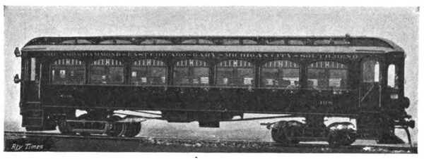
| |||
| Car for Express Service. |
The rail bonds on the rural sections of the line are of No. 0000 copper, with in. solid terminals placed under the base of the rail. The holes for the terminals were made with hydraulic punches, which left cone-shaped openings with their larger diameter at the top. The bonds were inserted from beneath the rail, and the terminals were then expanded into place with hydraulic compressors at a pressure of about 15 tons per square inch. It is stated by the Electric Railway Journal of New York, to which we are indebted for these particulars and the excellent drawings which accompany this notice, that after four months' use by heavy ballast trains and 70-ton locomotives, working over the unballasted track, not a single loose terminal was found, although a considerable number of the bonds had been broken by the movement of the loose joints. No. 0000 cross bonds were placed 700ft. apart. It is an interesting commentary on the social conditions prevailing in the vicinity of Chicago that it has been found impracticable to continue the use of these bonds on some sections of the line, owing to the activity of copper thieves, whose operations are a source of continual trouble and loss to other lines in the vicinity. To discourage this industry, it is now proposed to use heavy iron bars extending between and connected to both rails by the ordinary rail bonds, which are less attractive to the copper thieves.
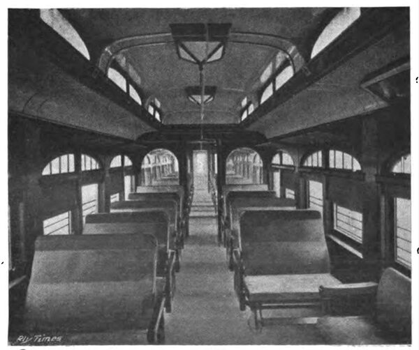
| |||
| Interior of Express Car. |
The line is equipped on the single-phase system, and a good idea of the details of the construction of the track and trolley line will be gathered from one of the accompanying drawings. The single-phase high tension circuit from the power station at Michigan City to each of the two sub-stations is carried on the tops of the same poles which support the trolley brackets. The supporting poles are of creosoted Southern pine. Each pole is 45ft. in length and 9 in. in diameter at the top, and is set 6 ft. in the ground, being bedded in concrete, which is firmly tamped at the top and bottom of the hole to afford secure bracing.
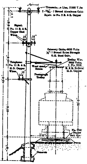 |
| Track and Trolley Construction. |
Aluminium conductors, equivalent to No. 2 copper, are used for the high voltage circuits. The two wires are placed 65 in. apart at the ends of a creosoted cross arm of 4 in. by 5 in. section. In place of cross-arm braces of iron, triangular blocks or gussets were spiked to of iron, triangular blocks or gussets were spiked to the poles under the high tension cross arms, and to prevent the tearing of the wood the usual lag-screw fastenings were replaced by galvanised hinged spikes with wedge-shaped points. The insulators on the transmission system are of porcelain, spray-tested to 80,000 volts. They are supported on special wooden pins impregnated by the vacuum process with a bituminous com-pound similar to that used for insulating railway motor fields. This transmission line is about 50 miles long.
A trolley voltage of 6,600 is used throughout, but arrangements have been made so that certain sections can ,if necessary, be fed with 700-volt current distributed through single-phase transformers. The trolley wire throughout is No. 0000 GE grooved section, supported by a 1/2 in. extra-strength double-galvanised catenary cable, except in city streets, where span construction is used. The cable has an 18in. sag between supports, which are 160 ft. apart on the straight and closer on curves. The trolley hangers are rods of 5/8 in. galvanised round iron with sister hooks at the top. Porcelain insulators tested to 20,000 volts support the catenary cable from the T-iron pole brackets. The trolley and catenary cable are anchored at both ends of every curve, and at one-mile intervals between curves. An extra pole is set for each anchorage, and the trolley and messenger are held against movement in either direction.
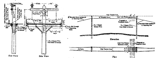 |
| Details of Catenary Trolley and High Tension Pole Line. |
To obtain an even deflection on curves, 14 in. Detroit type trolley clamps are used. The trolley splices are of cold-drawn copper tubing 36 in. long, soldered the entire length. To permit satisfactory operation of the pantagraph collectors at the very high speed desired (max. 75 miles per hour), it was found necessary to maintain the trolley exceedingly taut and the original splices 24 in. long, pulled out about as fast as they could be put in. It was found necessary to pull up the line with a dynamometer, so that the messenger and the trolley wire had the correct and uniform tension.
The line is provided with complete telephone arrangements, and the trains are handled by a dispatcher, assisted by the Telegraph Signal Company's system. A system of synchronous clocks, one placed at each meeting point, and a master-clock in the dispatcher's office, control the semaphore blades along the road. Any one of these boards may be thrown by the dispatcher. The semaphores indicate "stop" by a horizontal position of the arm by day and a red light by night in the usual manner. When a car is blocked by a semaphore the conductor proceeds to the telephone, obtains his order by the Egry register system, and, upon receiving an order from the dispatcher, sets the signal again to "safety" by pulling down a lever within the booth.
| |||
| A Straight Run on the Chicago and South Bend Line. |
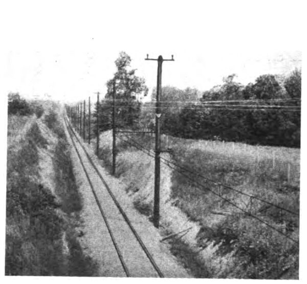
For fourteen miles the electric railway is parallel with the adjacent main line track of the Lake Shore and Michigan Southern Railway, and the Electric Railway Journal is responsible for the statement that frequent races take place between the steam and the electric trains. The electric cars frequently out-distance the steam trains, including the Twentieth Century Limited, a train well known to all travellers [sic] travelers between New York and Chicago as the finest thing that the Lake Shore and Michigan Southern Railway has to show.
The stations on the line are plain, well-designed, and not unattractive structures. The plan of the station at Gary, a brick structure, which is reproduced on the next page, may be taken as typical of the general arrangements.
The power station which supplies all the energy required for working the line is situated at Michigan City, on Lake Michigan, about midway between Pullman and South Bend. The single-phase current is thence distributed direct to the trolley wires at 6,600 volts, and to nine static transformer sub-stations at 33,000 volts. The equipment at the station consists of three turbo-generators, each with a capacity of 1,500 kw. Of the transformer stations, one is situated twenty-four miles on each side of the power station at the terminals of the 33,000-volt transmission line. There are also seven low tension sub-stations.
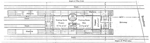 |
| Plan of A Typical Station on the Chicago and South Bend Railway. |
The general arrangement of the plant in the power station will be understood from the plan given below. The stack ,which is 210 feet high above the grates, is of Custodis radial tile, supported on concrete and pile foundations. In the boiler-room are six Babcock and Wilcox Stirling boilers of 500 horse-power capacity each, designed for 200 lbs. working pressure. Babcock and Wilcox superheaters have been provided with each boiler. These have sufficient surface to add 90 degrees super-heat to the steam at normal boiler capacity. The coal and ash handling plant is very complete. Coal storage for at least 10,000 tons is provided. The arrangements are so satisfactory that 160 tons of slack have been unloaded in ten hours by three men.
The three 1,500 kw. turbo-generators are of the Westing-house-Parsons type. Each has a capacity of 1,500 kw. single-phase, or about 2,000 kw. at the three-phase rating. The speed is 1,500 revolutions per minute. The three-phase units were chosen to provide against the possible future need of long distance transmission and possible commercial power load. There are two 100 kw. 125-volt direct-current exciters direct driven by Westinghouse compound engines. The switchboard is of the standard Westinghouse type, with electrically-operated oil switches. The general illumination of the power station, it may be added, is effected by mercury arc lamps of the Cooper-Hewitt type.
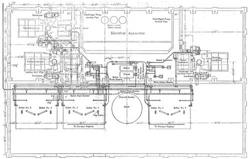 |
| Plan of Power Station at Michigan. |
The original rolling stock equipment included 24 passenger cars, 57ft. in length, and various cars for special service. A recent publication of the J. G. Brill Company, the largest manufacturers of street and electric railway cars in the United States, contains some particulars of ten express cars which they have recently constructed for the new line. As the illustrations show, these cars are of attractive design. They are 50 ft. long, and have an extreme width of 10 ft., which accounts for their roomy appearance. The height from the floor to the top of the clerestory roof is 9 ft. 5 in., and the distance between the truck centres is 28 ft. 4 in. The cars are divided into a smoking and a general passenger compartment, both being finished in quartered oak. The lighting is particularly effective.
The electrical equipment of the motor cars includes four Westinghouse No. 148 single-phase motors, rated at 125 horse-power capacity each, and multiple unit control. The cars have Westinghouse automatic air brakes and Peacock hand brakes. As security against any electrical injury the roofs of the cars are covered with 16 oz. sheet copper, well grounded. The cars start easily, and accelerate with little noise to speeds of more than 60 miles per hour.
