[Trade Journal]
Publication: Electric Railway Journal
New York, NY, United States
vol. 33, no. 15, p. 674-705, col. 1-2
THE CHICAGO, LAKE SHORE & SOUTH BEND RAILWAY
One of the most important single-phase installations now operating in the United States is the Chicago, Lake Shore & South Bend Railway, extending from South Bend, Ind., to Pullman, Ill., a distance of 77.5 miles. This new road furnishes direct communication in connection with the Illinois Central Railroad suburban service, between Chicago, Pullman, Kensington, Hammond, East Chicago, Indiana Harbor, Gary, Michigan City and South Bend. The territory around the south shore of Lake Michigan has recently shown such a remarkable growth in its industries and population that it evidently will afford traffic to support a line built in the most modern manner.
Several years ago a syndicate of Cleveland capitalists, recognizing the value of a road through this territory, obtained franchises and grants of especial value, including private rights of way through the new town of Gary. The Illinois Central Railroad Company agreed also to construct and equip that portion of the new line in Illinois and give the electric road the exclusive use of this track from Hammond to Pullman, Ill., at which point the electric line joins the Illinois Central suburban system.
The financing of the railway was undertaken and completed by Cleveland capitalists representing several of the leading trust companies in that city. A syndicate management was formed, with M. H. Wilson, vice-president of the Cleveland Trust Company, as the head. During the recent financial depression, when nearly all railway construction was either greatly restricted or entirely suspended, the work on this line was carried forward without delay, and all obligations were taken care of promptly.
The construction of the roadbed, inclusive of bridges, was done by a construction company organized for the purpose. The construction of the electrical distribution system, power house equipment and buildings was supervised by the Cleveland Construction Company, of Cleveland, Ohio, as consulting engineer. After careful examination of the different methods available for operation of the new line, the engineers recommended the use of the single-phase distribution system, which was adopted.
ROUTE
The eastern terminus is in the center of South Bend Ind., directly in front of the Oliver Hotel, near the City Hall and Court House. The company owns a street franchise in South Bend and private right of way within the city limits. In nine minutes after leaving South Bend terminal the cars can reach a point on the private right of way where a car can be run safely at high speed.
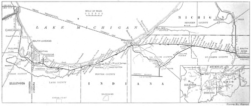 |
| Chicago, Lake Shore & South Bend Map of Route Traversed Between South Bend and Pullman, Showing Also Connections With Other Interurban Lines in Northern Indiana and Illinois |
The western terminus is at Pullman, Ill., where, for the present, passengers will transfer from and to the suburban trains of the Illinois Central Railroad, which run at intervals of 40 minutes to and from the heart of Chicago. An overhead footbridge has been constructed here for the convenience of the public, connecting the interurban platform with the suburban platform of the Illinois Central Railroad and permitting joint use of the depot at Pullman The train schedules are arranged so that cars of the new road make close connections with the Illinois Central suburban trains, offering quick and convenient service to the downtown district of Chicago at the Randolph and Van Buren Street stations of the steam road.
ROADBED AND TRACK
The roadbed has been constructed according to modern steam railroad practice; a maximum gradient of 2 per cent exists in but one place, which is the approach to a steam railroad crossing. Outside of cities the maximum curvature is 3 deg., with the exception of one 6-deg. curve. Tangents of 7, 8 and 14 miles exist, and all track work was designed for safe operation at the high speeds.
The main line track comprises 70-lb., A. S. C. E., 33-ft. rails laid on 6-in. x 8-in. x 8-ft. white oak ties spaced on 24-in. centers. The track in city streets is laid with 80-lb. Shanghai rails in 60-ft. lengths, with steel rail braces placed every 10 ft. All special track work is arranged for the standard M. C. B. flange and tread. Standard steam road spring frogs are used throughout. The switchstands are of the semaphore type, equipped with long-burning oil lamps with red and green lenses. At all crossings with main line steam tracks the grades are separated, except in cities, where derailers are installed. A grade crossing with the Chicago Outer Belt Line Railroad near East Chicago is protected by an interlocking plant, with a signal tower.
All bridges over other railways are of steel designed for Cooper's E-50 loading. Highway bridges are of reinforced concrete. There is but one section of pile trestle on the property, and this comprises the approaches to the Calumet River bridge. This wood trestle will be partly filled with sand and partly replaced by a steel viaduct.
Large culverts and cattle passes are of reinforced concrete. A minimum clearance of 17 ft. 6 in. above the rail is maintained under all structures over the track, to allow for catenary construction and the use of a pantograph.
| |||
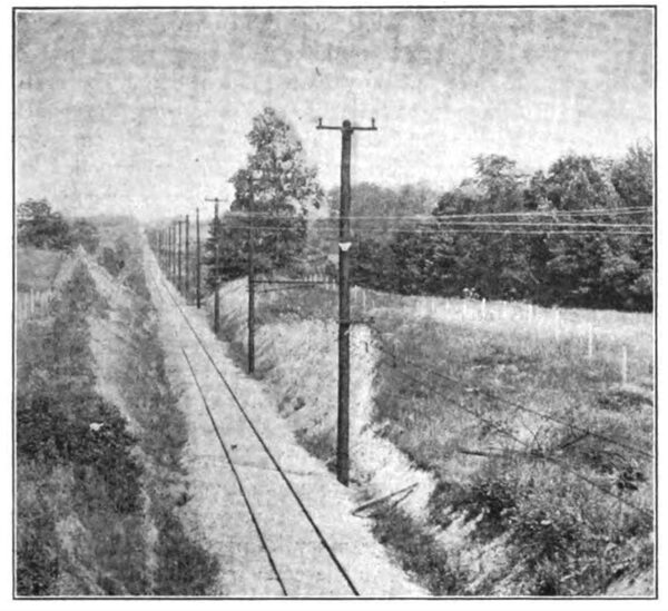
| Chicago, Lake Shore & South Bend A Long Tangent |
The rail bonds outside of cities are No. 0000 copper, with 7/8-in. solid terminals placed under the base of the rails. The holes for the terminals were made with hydraulic punches which left cone-shaped openings with their larger diameter at the top. The bonds were inserted from underneath and the terminals expanded into place with hydraulic compressors at a pressure of about 15 tons per square inch. After four months of use by heavy ballast trains and 70-ton locomotives operating over the unballasted track not one loose terminal has been found, although a considerable number of bonds have been broken by the excessive movement of the loose joints.
| |||
| Chicago, Lake Shore & South Bend Siding and Standard Switchstand |
No. 0000 cross-bonds were spaced 700 ft. apart. On account of the industry of copper thieves it was found impossible to maintain these bonds in the vicinity of Gary, and now it is proposed to replace the stolen bonds with heavy iron bars extending between the rails and connected to both by the ordinary rail bonds. The incentive for theft will thus be reduced to a minimum. All special work is shunted by two No. 0000 wires attached to cross-bonds at each end.
TRANSMISSION LINE
All the power for the operation of the entire road and the shops is generated in the Michigan City power station, which will be described in a later article. The trolley wire is fed near the station at the generating pressure of 6600 volts and the ends are also fed by two step-down transformer stations located respectively 24 miles east and west of Michigan City. The transmission voltage is 33,000 and the single-phase high-tension circuit from Michigan City to each of the two substations mentioned is carried on the tops of the same poles which support the trolley brackets. The pole line is exceptionally substantial. It is constructed of 45-ft. creosoted Southern pine poles with 9-in. tops. Each pole is set 6 ft. in the ground. Into each hole two barrels of concrete were placed, equally divided and tamped firmly at the top and bottom of the hole to afford a secure bracing.
| |||
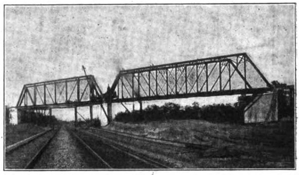
| Chicago, Lake Shore & South Bend Through Truss Bridge Crossing Tracks of the Pennsylvania Lines West and the Wabash |
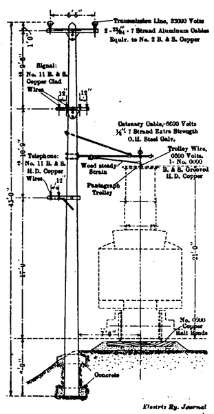
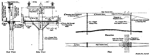
One of the engravings shows the details of a pole top of standard design. Stranded aluminum conductors of No. 2 copper equivalent are used for high-voltage circuits. The two wires are spaced 65 in. apart at the ends of a 4-in. x 5-in. creosoted cross-arm. In place of cross-arm braces of iron, triangular blocks or gussets were spiked to the poles under the high-tension cross-arms, and to prevent the tearing of the wood the usual lag-screw fastenings Were replaced by galvanized hinged spikes with wedge-shaped points specially made by the American Steel & Wire Company.
The insulators on the transmission system are 33,000-volt porcelain, spray tested to 80,000 volts, and were supplied by the Ohio Brass Company. They are supported on special wooden pins impregnated by the vacuum process with a bituminous compound similar to that used for insulating railway motor fields. The transmission line as here described is about 50 miles long.
TROLLEY LINE CONSTRUCTION
A trolley voltage of 6600 is used throughout. Arrangements are made so that in East Chicago, Indiana Harbor, Michigan City and South Bend, where it may be necessary to work on the trolley wire, it can be fed with 700-volt current distributed through single-phase transformers. The shop and yards are normally supplied with 700-volt current. No direct current is used in the trolley system. This use of alternating current only is important since it entirely avoids the complication of control apparatus required where car equipments must be operated on both direct and alternating trolley currents.
 |
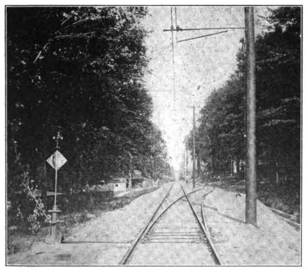
| Chicago, Lake Shore & South BendStandard Track and Trolley Construction |
The trolley wire throughout is No. 0000 GE grooved section, supported by a 1/2-in. extra-strength double-galvanized catenary cable, except in city streets, where span construction is used. Special care was taken in the specifications for the catenary cable to insure high strength and proper galvanizing. The cable has an 18-in. sag between supports, which are 166 ft. apart on tangents and closer on curves in proportion to the rate of curvature. The trolley hangers are rods of 5/8-in. galvanized round iron with sister hooks at the top. They are spaced 12 ft. apart. A wedge clamp serves to secure the trolley wire to the hangers. The overhead fittings were supplied by the Ohio Brass Company.
The catenary cable is supported on porcelain insulators tested to 20,000 volts, attached to T-iron pole brackets 9 ft. long with 5/8-in. over-truss rods. The trolley is further supported transversely by wood steady strains placed at every second pole on tangents and every pole on curves. When the catenary insulators were screwed to the iron bracket pins the pins were first wrapped with rubber tape. This affords some elasticity between the porcelain and the metal and has prevented a breakage of insulators which has been serious in several other installations. During four months of operation not one trolley or high-tension insulator has broken down in service.
The trolley and catenary cable are anchored at both ends of every curve and at 1-mile intervals between curves. An extra pole is set for each anchorage and the trolley and messenger are held against movement in either direction, thus preventing the falling of a length of wire in case of breakage. The catenary cable is anchored on each side of all overhead structures and the section between anchors carries no current.
 |
| Chicago, Lake Shore & South Bend Details of Standard Catenary Trolley and High Tension Pole Line |
To obtain an even deflection on curves 14-in. Detroit type trolley clamps are used. The trolley splices are of cold-drawn copper tubing 36 in. long soldered the entire length. To permit satisfactory operation of the paragraph collectors at the very high speed desired (max. 75 m.p.h.) it was found necessary to maintain the trolley exceedingly taut and the original splices, 24 in. long, pulled out about as fast as they could be put in. It was found necessary to pull up the line with a dynamometer so that the messenger and the trolley wire had the correct and uniform tension.
The trolley wire is sectioned about every 10 miles by a high-tension insulator with impregnated wood for insulation. Each breaker has a grounded brass band encircling the center of its insulation. This feature is of especial value at junction points of high and low voltage sections, because it assures safety from high voltage to any one working on the low-tension section. As the trolley and messenger are of the same potential porcelain spool section breaks are also installed in the catenary cable directly over the trolley section insulators. From either side of such a section-break a No. 0000 wire is run to a disconnecting switch on the pole opposite. Under ordinary operating conditions these switches remain closed, but in case of line trouble any switch can be opened by the dispatcher at Michigan City. The standard semaphore operating equipment of the Telegraph Signal Company is used for this purpose.
 |
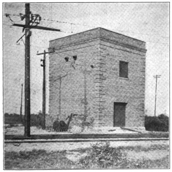
| Chicago, Lake Shore & South Bend Sections Through Static Transformer Substation Building |
In cities where a span wire suspension is used the construction is of standard type with heavy fittings. Steel poles are used in the downtown district in South Bend and high-tension porcelain strain insulators are used in spans and guys next the poles. Because of the excessive drop in both rail and overhead conductor within the cities when a potential of only 700 volts is used the length of the trolley sections is limited to about a mile. Transformers in fireproof stations are spaced accordingly and are fed from the 6600-volt trolley which is carried past each low-tension section on the poles at one side. Each section of No. 0000 trolley, which is arranged so that high or low voltage may be used, is supplemented by two No. 0000 stranded feeder cables, which parallel the trolley for substantially its entire length.
SUBSTATIONS
There are nine substations, two at the terminals of the 33,000-volt line, reducing to 6600 volts to supply the outer ends of the road, and eight available for supplying low-tension sections in towns if desired and at the car shop near Michigan City. The latter are connected between the trolley wire and track on both primary and secondary sides.
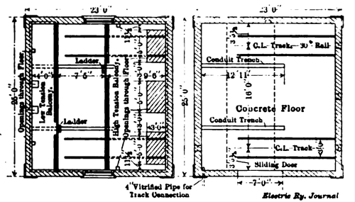 |
| Chicago, Lake Shore & South Bend Plans of Upper and Lower Floors of Static Transformer Substation Building |
The larger high-tension substation at East Chicago contains three 500-kw oil-insulated self-cooling single-phase transformers and the smaller, at Terre Coupee, contains two of the same units with room for a third. In these large substations the 6600-volt circuits have oil switches, but the 33,000-volt switches are the Westinghouse stick type using enclosed expulsion fuses.
| |||
| Chicago, Lake Shore & South Bend Static Transformer Substation |
The low-tension substations are located as follows: Three in East Chicago to supply 2 miles of main-line and 2 miles of branch-line trolley; two in Michigan City to supply 2.25 miles of main-line trolley; two in South Bend to supply 2 miles of main track and one at the car shops. All the low-tension substations are similar in equipment. That at Michigan City has duplicate equipments in one building. Each installation includes one 200-kw oil-insulated, self-cooling transformer with a stick-type, 6600-volt circuit breaker and low equivalent lightning arrester and an automatic oil circuit breaker in the connections to the low-tension trolley. The latter switch has a time lag which is materially shorter than that of the stick breaker.
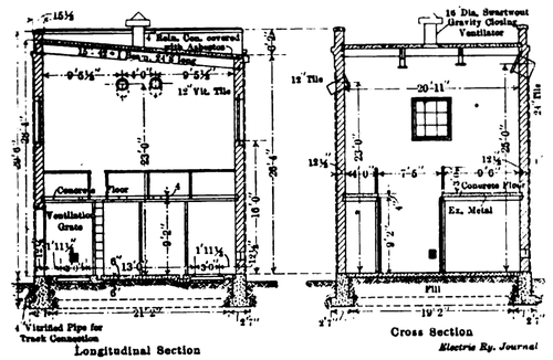
It was not practicable to equip the substation buildings with cranes and therefore the following expedients were used to assist in handling the transformers: In the high-tension substations the transformers are all set on trucks running on rails in the floor so they can be pulled out under a steel beam in the roof to which a chain hoist can be attached and any transformer lifted from its case. In the low-tension substations the track was not thought necessary, but each transformer was set on a concrete pedestal with a similar steel beam overhead so that the working part can be lifted out of the case and lowered to the floor. All the substation transformers are set high enough above the floor so that a standard oil tank can be rolled under the oil outlet when it is desired to drain the case.
| |||
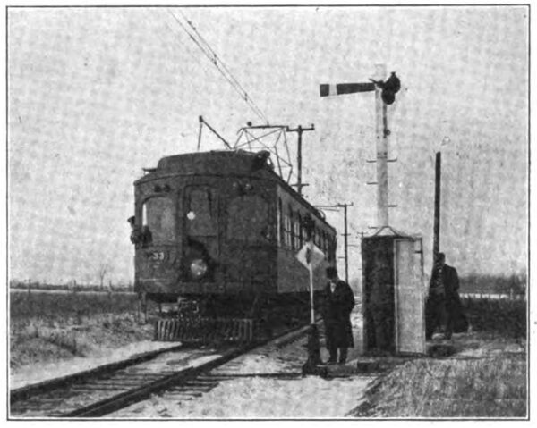
| Chicago, Lake Shore & South Bend Dispatcher's Signal and Telephone Booth at Siding |
The stick-type circuit breakers with enclosed fuses were adopted for the substation primary circuits because no substation attendance was expected; such breakers when seldom operated are less likely to get out of order than oil switches. The heavy time lag is also desirable so that the generating station breakers may have every chance to open first on an overload.
The substation buildings are simple fireproof structures. Accompanying engravings illustrate their general dimensions and design. During the past summer while the transformers were being dried out the trolley line 75 miles long was fed at its midpoint and the cars were satisfactorily operated over its entire length without using the transformer stations.
TELEPHONE LINE
There is one telephone circuit throughout the length of the line and a duplicate from Gary to Pullman, 17 miles. Each circuit consists, of a pair of No. 11 copper-clad steel wires supplied by the Duplex; Metals Company. The telephone circuit is half spiraled every second pole with vertical double insulator brackets. Owing to the fact, that the telephone line is on the same poles with the 33,000-volt transmission line and also with the 6600-volt trolley, extreme care was exercised in its construction. In addition to the transpositions a 1-to-1 ratio transformer, insulated for 30,000 volts and with a grounded core, was installed for each telephone. These transformers perform two valuable functions: They eliminate substantially all of the noise due to induction and leakage and also protect the telephone instruments from high-tension current. It is said that it is possible to cross one of the telephone wires with the 6600-volt trolley wire and still maintain ordinary conversation.
| |||
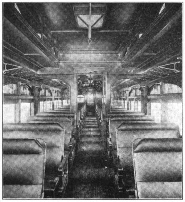
| Chicago, Lake Shore & South Bend Interior of Passenger Car |
In South Bend, owing to the obstruction of trees along the line, arrangements have been made with one of the local telephone companies to support the two railway wires through the city to the ticket office on the telephone companys poles. A transformer similar to those mentioned above was installed at the city limits, thus protecting all the local wires in case of a cross or ground.
Telephone booths of sheet steel are placed at each siding and at important stops. These booths contain a telephone instrument, block signal apparatus, described later, and an Egry autographic register for trainmen's use in taking and recording orders. All wires are brought into the booths under the tracks in steel conduit and a switch is located in the booth interlocking with the door. When entering the booth a party desiring to use the telephone must first close this switch and again he must open the switch as he leaves or the door of the booth cannot be closed. All booth telephones are without ringers and current is taken from the lighting system of the office building at Michigan City to operate the dispatchers ringer. The switchboard at the dispatchers office has provisions for extra lines and is connected to the long-distance Bell lines.
SIGNAL SYSTEM
To assist the dispatcher in handling trains with the telephone the Telegraph Signal Companys system, made by the Stromberg-Carlson Telephone Manufacturing Company, of Rochester, N. Y., was installed. A system of synchronous clocks, one located at each meeting point, and a master clock in the dispatchers office, control the semaphore blades along the road. Any one of these boards may be thrown by the dispatcher. The semaphores indicate stop by a horizontal position of the arm by day and a red light by night in the usual manner. When a car is blocked by a semaphore the conductor proceeds to the 'phone, obtains his order by the Egry register system and upon receiving an order from the dispatcher sets the signal again to safety by pulling down a lever within the booth.
| |||
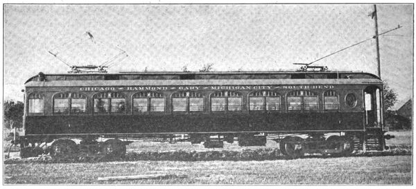
| Chicago, Lake Shore & South Bend Standard Motor Passenger Car |
The clocks are operated by weights and require winding about once in 30 days. The signal circuit consists of two hard-drawn copper wires. This installation has given full satisfaction.
CARS AND EQUIPMENT
The rolling-stock equipment includes 24 large passenger cars, one high-powered utility car, four smaller cars for local service, 20 Hart convertible cars, 3 box and 12 flat cars and 1 Russell No. 1 snow plow. The passenger cars were described and illustrated in the Electric Railway Review for May 23, 1908, page 628. Express cars are now being constructed. The passenger cars were built by the Niles Car & Manufacturing Company.
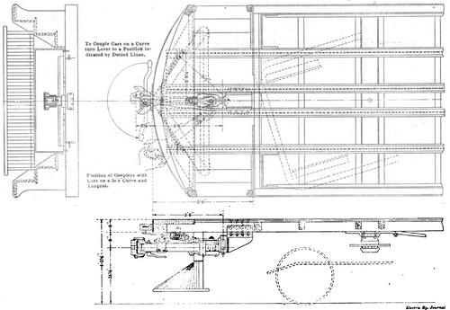 |
| Chicago, Lake Shore & South Bend Application of Janney Radial Couplers to Standard Passenger Cars |
From the following general dimensions presented it will be noted that the passenger-car bodies are of the regular steam coach width, which is a desirable feature that few interurban railways have been able to obtain.
Length over all................................. 57 ft. 2 in.
Length over body............................. 47 ft. 4 in.
Width over all.................................. 10 ft.
Height from floor to top of roof...... 9 ft. 5 in.
Truck centers................................... 35 ft. 6 in.
Width of aisle................................... 24 in.
Width inside..................................... 9 ft. 7 1/2 in.
The underframing of the passenger cars is of semi-steel construction with double outside sills that have 5/8-in. x 10-in. steel plates bolted between them. The four center and intermediate sills are 6-in. I-beams and extend the full length of the car from buffer to buffer. End doors in the vestibules with spring buffer platforms are provided so that the passengers may pass from car to car. Over the vestibule step openings are self-opening trap doors manufactured by the O. M. Edwards Company.
The interiors of the car bodies are richly finished in polished dark mahogany. The ceilings are full Empire style, artistically decorated and illuminated with incandescent lamps enclosed in Holophane bowls. An individual lamp is also supported over each seat by an artistic bronze bracket. The passenger cars have a seating capacity for 60 persons; the seats, manufactured by Hale & Kilburn, have stationary backs, foot rests, bronze grab and offset handles and arm rests and are upholstered in leather. The cushions are 38-in. long and the seats measure 48 in. from the inside of the car to the outside of the arm rests. A toilet room is located at the rear of the main passenger compartment.
| |||
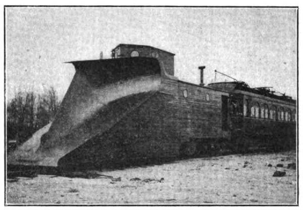
| Chicago, Lake Shore & South Bend Russell Snow Plow Pushed by Standard Passenger Car |
These cars are mounted on Baldwin Locomotive Works, Class 90-35 M. C. B. trucks with 7-ft. 6-in. wheel base. Each truck was designed for a working center plate load of 35,000 lb. Standard Steel Works solid steel wheels, 38 in. in diameter, are mounted on axles 6 1/2 in. in diameter at the center, 7 1/2 in. at the gear seat and 7 in. at the wheel seats. The journals are 5 1/2 in. x 10 in., inclosed in Symington journal boxes. Ball-bearing center bearings are used on all trucks.
The electrical equipment includes four Westinghouse No. 148 single-phase motors rated at 125-hp capacity each and multiple-unit control. The special equipment of the cars includes Peter Smith hot-water heaters, Westinghouse automatic air brakes, Peacock hand brakes, Lintern markers and classification lights and Knutson trolley retrievers.
| |||
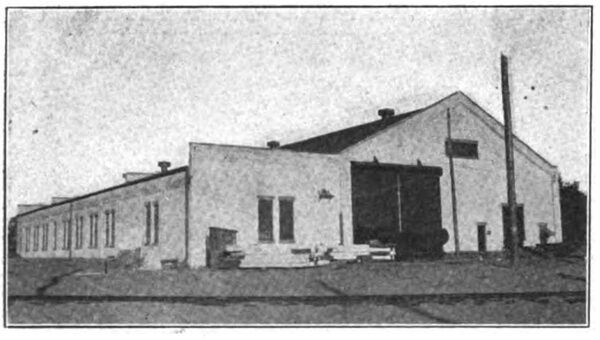
| Chicago, Lake Shore & South Bend Repair Shops at Michigan City |
All the cars are equipped with Janney radial M. C. B. coupler equipment made by the McConway & Torley Company, of Pittsburg, Pa. The coupler head is the same as that used extensively on the passenger coaches of steam railroads. Wide lateral movement of the coupler is required, owing to the severe curves over which the cars travel, while to automatically hold the coupler in the central position on the car for coupling on straight track, a special centering bar and spring are mounted immediately over and parallel with the drawbar. At the forward end of this centering device is a cam and lever, by means of which the compression can be removed from the centering spring, after which the coupler may be moved to any point required for coupling on curved track. On the side of the coupler head is a horn or bracket made to engage the guard arm of the opposing coupler, its object being to minimize the tendency of the couplers to buckle and to strengthen them in pushing cars around curves.
As security against any electrical injury the roofs of the cars are covered with 16-oz. sheet copper well grounded. The exteriors of the cars are painted in three shades of maroon with silver lettering. This exterior finish is similar to that of the Chicago & Alton limited trains. Each passenger car is provided with two wheel trolleys and a pantograph collector, the latter being used on 6600-volt current only. By means of a change-over switch either trolley can be operated on either voltage as desired.
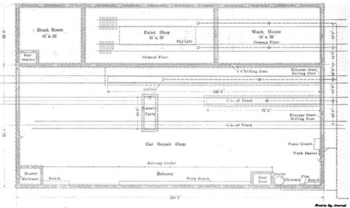 |
| Chicago, Lake Shore & South Bend Plan of Repair Shops at Michigan City |
The utility car is a combination equipment which can be used for a construction locomotive or for hauling freight trains. The underframing of this car is built of heavy steel with continuous sills 40 ft. long. The electrical and braking equipment is similar to that of the passenger cars. This car has been fitted with a box body. Both ends of the body have double doors through which such large pieces of freight as theatrical scenery may be loaded.
The interurban rolling-stock equipment since the beginning of operation in the summer has given excellent satisfaction. The cars start easily and accelerate with little noise to speeds of more than 60 m.p.h. For 14 miles west of South Bend the electric railway is parallel with and adjacent to the main-line track of the Lake Shore & Michigan Southern Railway. Frequent races take place between the steam and the electric equipments and it is said that the electric cars have time and time again out-distanced the steam trains, including the famous Twentieth Century Limited.
 |
| Chicago, Lake Shore & South Bend Floor Plan of General Office Building at Michigan City |
The four small cars earlier mentioned are in service in East Chicago and Indiana Harbor on about 4 miles of low-tension line. These cars are 42 ft. long, of the Brill semi-convertible type, and are equipped with Brill and Baldwin trucks. The motor equipment consists of two 75-hp Westinghouse single-phase motors with platform control so arranged that the cars may be operated on the 6600-volt sections.
REPAIR SHOPS
The repair shop of the system is located at East Michigan City and consists of a large building of sand-lime brick with a steel truss roof. It includes a general motor repair shop, armature room, store room, paint shop and wash room, all steam heated and well lighted. Two pits and a transfer table, are provided, together with swinging cranes, compressed air and all the necessary tools for car repairs, including a 400-ton wheel press and a wheel-turning lathe. The tools are driven by 30-hp Westinghouse induction motors. Fire protection is provided by a 25,000-gal. tank erected on a 60-ft. tower and a centrifugal pump of 500 gal. per minute capacity, operated by an induction motor installed in a fireproof building 50 ft. distant from the main building. There is also a separate fireproof building adjacent to the shop for storing sand, oil and wrecking tools. The main repair shop presents an unbroken space without columns or partitions.
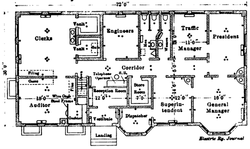
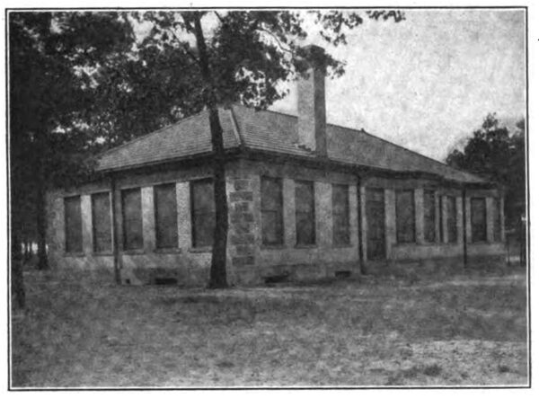
OFFICE AND STATION BUILDINGS
The general offices are also located at East Michigan City, adjacent to the repair shops. The office building is of white brick with red tile roof. It is one story high with a basement and contains offices for the general manager, auditor, electrical engineer, traffic manager, engineers, accountants, cashier, superintendent and train dispatchers, as well as telephone desk room, reception room, general store room, toilets, fireproof vaults, etc. The water supply is provided from the general storage tank for the shops and the lighting from a step-down transformer feeding from the 6600-volt trolley. The office building is splendidly located, being substantially at the center of the system and but 10 minutes' ride by local cars from the business district of Michigan City.
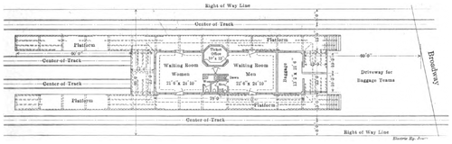 |
| Chicago, Lake Shore & South Bend Plan of Station and Platform at Gary, Ind. |
At Gary, Ind., is a substantial brick station building 23 ft. x 78 ft., with tile roof, similar in general appearance to the office building previously described. This contains a ticket office, waiting rooms, baggage room, etc. The location is near the plant of the. United States Steel Corporation at the head of Broadway and is close to several steam road stations. A 200-ft. platform, level with the car floor, is provided for the use of passengers and the handling of freight and express. It is expected that the business between Gary and Hammond, East Chicago and Chicago will be extremely heavy and a storage yard and Y for turning have been provided.
| |||
| Chicago, Lake Shore & South Bend General Office BuildIng at Michigan City |
At South Bend a large waiting room and ticket office have been secured on Main Street, close to the Oliver Hotel, opera house, county building, city hall and the terminus of the other traction lines. Arrangements also have been made here for the proper handling of freight and express, for which the company is now making especial preparations.
| |||
| Chicago, Lake Shore & South Bend Terminal at KensingTon on Illinois Central Railroad |
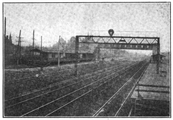
At Michigan City the depot for the present is located in a store building adjacent to the tracks in the center of the city. The waiting room in this building is 20 ft. x 57 ft. in size and at the rear is a freight and baggage room 20 ft. x 30 ft. Local ticket offices also are being installed in all of the larger cities and towns through which the road passes.
| |||
| Chicago, Lake Shore & South Bend Station at Gary, Ind. |
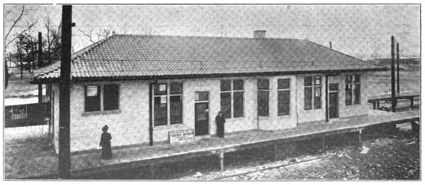
Neat wooden waiting stations and platforms are located at the principal highway crossings and stopping places. The road crossings have been named so that there may be no confusing of numbers. At each road intersection, crossing post or way station is posted a time-table showing when trains are due to stop at that point. These time-tables are painted with white letters and black background on a piece of tin about 6 in. x 8 in. in size. The permanent-way fixtures have all been installed with regard to the best high-speed service. Semaphores and switch targets are clear of the pole line, whistle posts are placed for each highway and at each local stop posts have been set so that the motorman may more easily stop the car with the rear platform at the best loading point. The name of the next station is painted clearly on each whistle post and every fifth pole is numbered so that car crews may accurately report location.
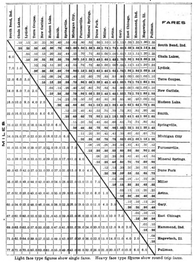 |
| Chicago, Lake Shore & South Bend Through Passenger Tariff and Mileage Chart |
The schedules offer a local train in either direction every two hours and limited trains in between. On the west end between Gary and Pullman the local service is on 40-minute headway to connect with each Illinois Central Railroad suburban train going into Chicago. An accompanying engraving exhibits the mileages and the one-way and round-trip fares between all stations on the new road. Because of the excellent roadbed the cars of this road can make fast time. The limited trains between Pullman and South Bend make the run of 77 miles in 2 hours and 15 minutes. It requires 45 minutes to travel by the Illinois Central suburban express trains from Randolph street to Pullman, a distance of 15 miles. Thus the trip between Chicago and South Bend, 92 miles, can be made in three hours. Limited trains make stops in but six towns in the 77-mile run. Local trains stop on signal at all highway crossings in the country and at all street crossings in the cities, and make the 77-mile run in 2 hours and 55 minutes.
The personnel of the managerial and operating staff of the Chicago, Lake Shore & South Bend Railroad includes: H. U. Wallace, general manager and purchasing agent; G. A. Buchanan, superintendent; Fred Hume, electrical engineer; T. R. Cummins, engineer maintenance of way; George F. Faber, traffic manager.
