[Trade Journal]
Publication: High-Tension Power Transmission
New York, NY, United States
vol. 2, no. 1, p. 25-30, col. 1
NOTES ON EXPERIMENTS WITH TRANSFORMERS FOR VERY HIGH POTENTIALS.
BY PROF. HAROLD B. SMITH, Worcester Polytechnic Institute.
The attention of the writer was first directed toward the problems involved in the production and application of high potentials of low frequency by certain of the exhibits at the Chicago Exposition of 1893, and particularly by the discussion before the International Electrical Congress of 1893 on power transmission.(1)
As a result of this interest, during the college year 1893-94, in connection with the direction of the School of Electrical Engineering at Purdue University, two senior students(2) at the University designed and constructed, under the writer's supervision, a small transformer to give an effective secondary potential of 10,000 volts.
This transformer was constructed with but slight knowledge of the difficulties involved and was a failure except for the many valuable lessons received from successive attempts to operate it under the proposed conditions.(3) The following year this transformer was reconstructed by two senior students at the University (4) and was operated for some time before a final break-down occurred, but there could be no hope for the final success of such a transformer.
Following a suggestion by Tesla in a paper before the Institution of Electrical Engineers, (5) paraffin oil was heated, and by means of an air-pump drawn into a closed metal-lined box containing the core and windings. The oil apparently penetrated to all the surfaces of the core and windings, and it is probable that, so far as this part of the work is concerned, good results were secured; but unfortunately rubber insulation was used on the secondary winding and this was promptly softened by the oil.
While this transformer was a failure in all respects, except that it led to success with later transformers, no responsibility for this failure should rest upon the four young men who assisted in its design and construction, as the writer was responsible for the important features of the design and the failure should be assumed by him alone.
On account of the pressure of many duties and the interruption of this work occasioned by the acceptance of the chair of Electrical Engineering at the Worcester Polytechnic Institute in 1896, this work was not continued until the college year 1897-98, when two graduate students (6) in electrical engineering at the Institute, under the writer's direction, undertook the design and construction of a 150,000-volt transformer, which was completed early in the spring of 1898. The experiences with the transformer of 1894, the succeeding interval of four years for occasional study of the various causes of its failure, together with many valuable suggestions from Prof. J. O. Phelon of the Worcester Polytechnic Institute and the remarkably able manner in which the two men who were engaged upon this work carried out the details of the design and construction, account for the thorough success of this second transformer.
A reference to this transformer, which had a ratio of voltages of 1 to 1500, and an illustration showing its construction appear in the Transactions of the American Institute of Electrical Engineers (7) in a note communicated by the writer to the discussion of the paper by Steinmetz on the "Dielectric Strength of Air.(8) More detailed descriptions of this transformer appear elsewhere (9) so that no extended description need be given here. However, a statement of experience with this transformer for the past six years may have some interest and value.
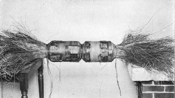 |
| Fig. 1--10,000-Volt Transformer, 1893. |
| |||
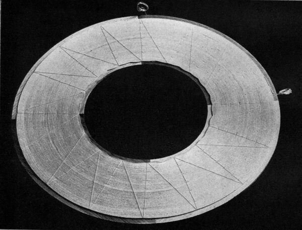
| Fig. 2--Coil of 200,000-Volt Transformer, 1904. |
For several years the transformer was in fairly constant experimental service in the laboratories of the Institute on work (10) which involved operation at potentials as high as 190,000 effective volts and for many days was operated for 10 hours per day at 175,000 effective volts. Nearly a year ago, this transformer was sold to be used for commercial testing by a company manufacturing insulators and information has been received recently of its continued satisfactory daily service at potentials ranging up to its rated capacity.
This transformer was exhibited at the Saratoga (1903) Convention of the American Street Railway Association, and at this time several coils of the secondary winding were injured in shipment and had to be replaced; with this exception, practically no difficulty has ever been experienced in its operation. It was designed primarily for experimental work in the laboratories of the Worcester Polytechnic Institute and many details of construction would naturally be changed in a design intended for commercial service, although the general features of the design have demonstrated their reliability for this class of work.
In the fall of 1899, two seniors (11) in electrical engineering at the Institute undertook the development of a transformer for still higher potentials and in the spring of 1900 produced, under the direction of the writer, a transformer designed for a secondary potential of 330,000 volts at 60 cycles per second; but under test, this transformer failed to develop potentials higher than 210,000 effective volts at the terminals of the secondary circuit.
| |||
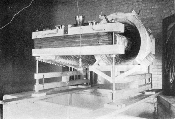
| Fig. 4--500,000-Volt Transformer, 1901. |
| |||
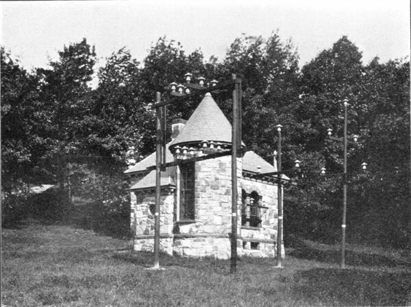
| Fig. 6--High-Potential Laboratory, Worcester Polytechic Institute. |
Failure to operate this transformer at higher potentials may be attributed, in part, to an absence of knowledge at the time of its design, of phenomena which occur at the higher potentials and which had not been observed in the operation of the 1898 transformer below 175,000 volts. In part, the failure of this transformer may also be attributed to defects introduced by frail construction and faulty design of the windings, as the transformer was regarded as a purely experimental affair, and expensive construction was avoided whenever possible and in too great a measure for satisfactory results. However, as in the case of the 1894 transformer, failure to accomplish the results anticipated led to a closer study of the phenomena involved in this class of work, and to success later in the production of a transformer for even higher potentials.
During the college year 1900-01, four graduate students (12) in electrical engineering at the Institute undertook the design and construction of a 500,000-volt transformer at the suggestion and under the direction of the writer. This transformer was in operation early in May, 1901, and at that time developed a secondary potential, at 60 cycles per second, which was capable of disrupting a 48-in. (1.22 meter) air-gap between sharp needle points.
As this is undoubtedly the first transformer and, so far as the writer is informed, the only transformer which, up to the present time, has, with a single transformation or even with several transformations by a number of transformers, secured low-frequency potentials in the neighborhood of one-half million effective or three-quarters of a million maximum volts, a brief description may be of value.
The design of this transformer called for a ratio of transformation of 1 to 2520, at 60 cycles, and a maximum core density of 8600 gausses, when at a secondary potential of 500,000 effective volts. The primary winding consisted of 46 turns of heavy stranded conductor 23 turns on each core-in series for a primary potential of 200 volts, 60 cycles, giving a maximum magnetic flux of about 1,600,000 maxwells at full rated voltage. The secondary winding was subdivided into 66 coils, each of which was further subdivided by cotton tape into four sections. There was a total of 115,920 turns of number 32 B & S double cotton-covered wire in the secondary winding. Each coil was wound in a spool turned from thoroughly seasoned white pine of the very best quality and carefully selected stock. The cross-section of the spool is shown in Fig. 5, and the outside diameters of the spools ranged regularly from 16 ins. up to 32 ins.
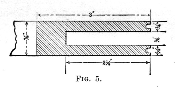 |
| Fig. 5 |
The middle of the secondary winding was connected to the core and to the primary winding, and carefully earthed in most of the work which has been done with this transformer, although it has been operated on a number of occasions without earthing the secondary circuit. The primary circuit, supplied with current from a generator which may be regulated as desired, was always earthed for the protection of the operator.
This transformer has been used for three years upon work of investigation connected with various thesis subjects (13) upon which students at the Institute have been engaged, together with some work carried out personally by the writer upon the dielectric properties of air and oils. During this time, it has been found necessary upon two or three occasions to cut out a few faulty coils of the secondary winding; but when it is stated that this winding contains about 125 miles (about 200 km) of No. 32 B & S wire which was not wound in layers, although each coil may develop from 8000 to 9000 volts, this is not surprising. Tests made with this transformer indicate that, with the substitution of a modification of the secondary winding which has been introduced by the writer in transformers of more recent design, a potential of not less than 750,000 volts effective, or over a million volts maximum, can be secured from this transformer. As soon as suitable opportunity presents itself, it is proposed to make this change. The transformer is located in a separate transformer-house on the campus of the Institute, at some distance from other buildings on account of the fire risk occasioned by over a thousand gallons (3800 litres) of oil required for insulating the secondary winding.
On May 27 of this year, an order was placed with the writer for a 200-kw, 300,000-volt transformer which was shipped to its destination July 18, and has recently been placed in operation and accepted by the purchaser (14). As this transformer was designed along lines which will permit its operation at considerably more than its rated voltage and power output and probably constitutes the largest transformer yet built for very high potentials, the writer has been permitted to give the following brief description:
| |||
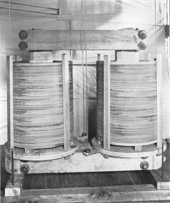
| Fig. 7--Side View of 200 Kw 200,000-Volt Transformer, 1904. |
Fig. 7 shows an assembled view of the transformer core and secondary winding ready to be immersed in the oil contained in the transformer tank. The connections to the primary and secondary circuits are so arranged as to permit full rated power output at secondary potentials of either 75,000, 150,000 or 300,000 volts, 60 cycles. The maximum ratio of primary and secondary turns is 316, as the primary is designed to be supplied from a 1040-volt generator. The secondary contains about 33,000 turns of about 42 miles (about 68 km) length of conductor.
On Aug. 15, work was begun upon two transformers which are not yet finished, but of which some information can be given. Fig. 2 shows one coil of the secondary winding, which contains 280 turns of double cotton-covered wire having a section of copper of .004 in. x .05 in.
These transformers have been given a preliminary rating of 200,000 volts, but have been designed along lines which should permit of their operation at potentials considerably above this value.
One of the transformers is provided with a removable yoke so as to permit of its experimental use as an induction coil of large output, when so desired, and both transformers have been provided with extra leads so as to permit of a variety of combinations for experimental work at the Institute on single, two and three-phase circuits of very high potential. One hundred coils, such as the one shown in Fig. 2, will constitute the secondary winding of each of these transformers, so that each secondary will have a length of about 25 miles (about 40 km) of wire.
1. Proceedings of the International Electrical Congress, 1893, pp. 422-472.
2. G. G. Phillips and S. Moore, Thesis, "The Design and Construction of a High Voltage Transformer." Purdue University, 1894.
3. Primary, 1000 volts; secondary 10,000 volts; frequency 140. Primary had 248 turns. No. 14 B & S, and secondary 2840 turns No. 22 B & S. Core made of No. 16 iron wire.
4. Messrs. A. C. Bunker and C. C. Chappelle.
5. Journal of the Institution of Electrical Engineers, Vol. 21, p. 79.
6. Ellery B. Paine and Harry E. Gough, Thesis, "High-Potential Discharges in Dielectrics." Worcester Polytechnic Institute, 1898.
7. Transactions American Institute of Electrical Engineers, Vol. 15, p. 328.
8. Ibid, p. 281.
9. Journal of the Worcester Polytechnic Institute, Vol. 1, p. 356; Electrical World, Vol. 32, p. 63.
10. S. S. Edmands and W. E. Foster, Thesis, "Distribution of Potentials Between High-Potential Conductors." C. E. Eveleth and E. F. Gould, Thesis, "Dielectric Strength of Oils." O. P. Tyler and S. T. Willis, Thesis, "High-Potential Tests of Solid Dielectrics." E. H. Ginn and W. J. Quinn, Thesis, "Surface Leakage on High-Potential Insulators." J. M. Bryant, Thesis, "The Commercial Production of Ozone." A. L. Cook, A. P. Davis and J. B. Wiard, Thesis, "Leakage Losses on High-Potential Transmission Lines." W. M. Adams and W. H. Sigourney, Thesis, "Surface Leakage on High-Potential Insulating Materials." H. W. Morehouse and E. L. Stone, Thesis, "The Distribution of Potentials Between High-Potential Conductors."
11. H. I. Cross and S. E. Whalley, Thesis, "The Design, Construction and Test of a High-Potential Transformer." Worcester Polytechnic Institute, 1900.
12. R. S. Beers, F. R. Davis, E. H. Ginn, W. J. Quinn, Thesis, "The Design, Construction and Test of a 500,000-Volt Transformer." Worcester Polytechnic Institute, 1901.
13. R. S. Beers, F. R. Davis, E. H. Ginn, W. J. Quinn, Thesis, Investigation of the Dielectric Strength of Air and Oils." L. Day and C. F. Harding, Thesis, "Investigation of the Leakage Loss Between High-Potential Transmission Conductors." A. L. Cook, A. P. Davis, G. E. Munroe, E. W. Kimball, J. A. Sandford, Thesis, Investigation of the Leakage Loss Between High-Potential Conductors."
14. The Locke Insulator Mfg. Co., Victor, N. Y.

