[Trade Journal]
Publication: Canadian Electrical News
Toronto, Ontario, Canada
vol. 16, no. 9, p. 250-257, col. 1-2
The Ontario Power Company of Niagara Falls
BY V. G. CONVERSE, ELECTRICAL ENGINEER ONTARIO POWER. COMPANY.
Briefly outlined, this company's development comprises the taking of water from the upper Niagara River, leading it through pipes and penstocks to turbines in a station below the falls and there utilizing its energy for the generation of electricity which is transmitted to a second station on the bluff above and thence distributed.
| |||
| Fig. I.--View of Head Works, Ontario Power Company. |
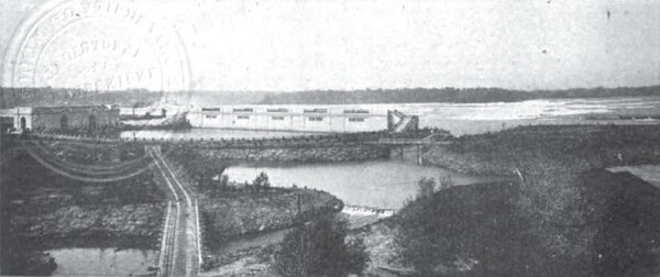
Starting from the headworks, the water is diverted tinder curtain walls into two forebays in series, so pro-portioned as to provide the proper velocity through screens and gates, and so constructed as to exclude ice. From the inner or second forebay the water is conveyed in large conduits underneath the ground, along the outskirts of Queen Victoria Park for a distance of approximately one and one-quarter miles to a point adjacent to the Horseshoe Falls.
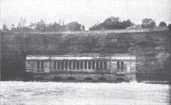
At the terminus of the eighteen-foot conduit now completed, nine-foot steel penstocks equipped with gate valves extend first vertically and then horizontally, each to a turbine unit in the generating station. This building is nearly on a level with the river below the Falls, and is as close to the cataract as conditions allow. It is to be noted that the full head of the water between the upper and lower rivers has been acquired so far as was feasible from an economic standpoint.
| |||
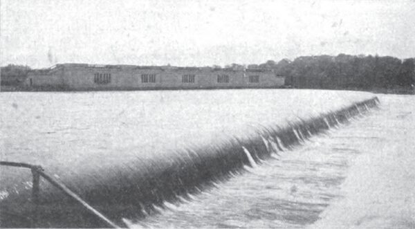
| Fig. 2.--Overflow of Outer Forebay, Ontario Power Company. |
Each generating unit consists of a horizontal double turbine direct-connected to a generator. The units are alike in appearance, but the fourth, or last generator installed, possesses an advantage over the others in a twenty per cent. increase of capacity. The completion of the station and the equipment of it will be but an extension of the present form until, according to existing plans, there is an installation under the one roof sufficient for the continuous delivery of 200,000 horse-power of electrical energy.
From the generating station the electric current is carried by underground cables to the distributing station on the bluff, 260 feet above and 600 feet back from the generating station. In the distributing station are the switching and transforming apparatus and the metering and controlling devices for the operation of the plant. From the distributing station go the overhead circuits of various voltages for the transmission of the power to the consumer.(1)
The hydraulic portion of the plant and a part of the generating equipment having been in service for nearly a year, it is befitting to remark that in general the plan of the headworks to exclude ice the operation of the first main conduit with its spillway, the location and action of gates, valves and reliefs for the water, together with the results obtained from turbines and generators, have proven most satisfactory. That all of these features have been put into use without a single difficulty, and have perfectly performed their various functions, is but the logical outcome of the careful study, painstaking attention to detail, and thorough execution of this portion of the work.
The coming month will witness the putting into service of the transformers, switches and other high voltage equipment of the distributing station, and the delivery of power to the enormous transmission system of the distributing company for use throughout western New York, and somewhat later will come the electrification of the circuits now building for the delivery of power to the Niagara district of Canada.
| |||
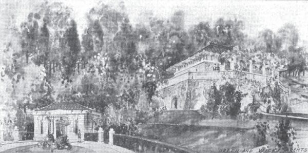
| Fig. 3.--Entrance and Spillway Buildings, Ontario Power Company. |
| |||
| Fig. 4.--Generating Station, Ontario Power Company. |
| |||
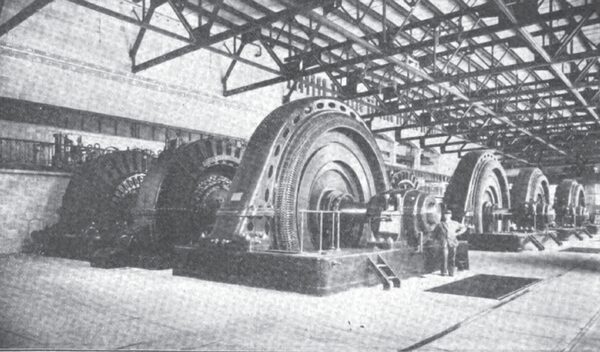
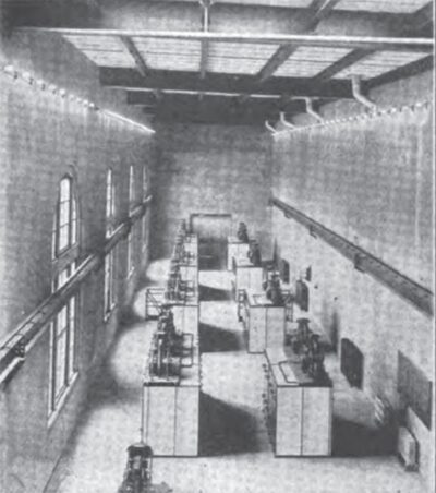
| Fig. 5.--Interior of Generating Station, Ontario Power Company. |
Much has been said of the disfigurement of the park by the power plant construction, and this with considerable justice, but to one who now sees the construction nearing completion, and notes the new channels and islands at the Dufferin Inlet, the provisions for the observation of the rapids and falls, the harmonious character of the buildings, and the general air of fitness and refinement, it cannot but appear that the retention of the beauty of Niagara has been in mind as well as its exploitation for power. At present the only exceptions are the entrance and overflow buildings at the terminus of the main conduit. Their erection, which of necessity has been delayed to the last, is in progress and very pleasing buildings will shortly hide the present unsightly constructions.
It is the essential purpose of this paper to describe the electrical features of the Ontario Power Company's plant, to which attention will now be directed. Three generators of 10,000-H.P. capacity each, and a fourth of 12,000-H.P. are now in service. These machines are wound for three-phase current at 12,000 volts, and 25 cycles, and have revolving fields, the speed of rotation being 187.5 R.P.M. The total weight of a generator is 231 tons. Assembly, including the building up of the laminated iron of the rotor, and the winding and insulating of the armature, has been done entirely upon the ground. Two exciters have been provided, each of 500-II.P. capacity at 250 volts, and driven by its own turbine. A single exciter is of sufficient capacity for the fields of six generators.
| |||
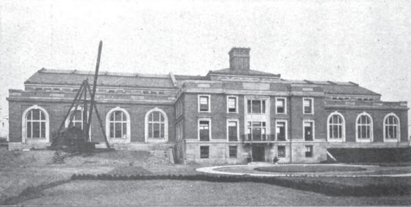
| Fig. 6.--Distributing Station, Ontario Power Company. |
The leads from the generators are single conductors, insulated with treated cambric. These leads, each in a separate compartment, are mounted on porcelain insulators, ample clearances to ground being allowed on all sides. The compartments are built up of thin shelves of reinforced concrete secured to the concrete sub-structure of the building, and are closed by doors of asbestos which may be readily removed for inspection. At no place are the leads of more than three generators brought into proximity, and the leads of each set of three generators where they approach their respective oil switches on the gallery in the generating station are so protected and isolated from each other that grounds or short circuits would seem to be impossible.
Field circuits, exciter leads and control wires are carried in iron conduit and are either in separate passages or at respectful distances from power wires.
The electrical equipment of the generating station, aside from the machines, consists of a switchboard, having a panel for each generator upon which are mounted an electrically controlled field circuit breaker, an ammeter, and a control switch for tripping the first generator oil switch; also a panel for each exciter, containing the customary switches, and a voltmeter and ammeter. Secondary to this board is another panel board for the distribution of alternating and direct current for the light and power service in the station, and also for the distant control of the valves in each turbine penstock. Back of the exciter switchboard are small panels, one for each pair of generators, on which are mounted the terminals of the control wires and the relays for the automatic operation of the oil switches.
There are also the generator oil switches, field rheostats, and small motors on the turbine governors all of which are controlled from the distributing station.
The detail electrical equipment of the station is simple, and being wholly on the operating gallery is within easy access of the operator. Ordinarily the operator is required to merely attend to the supply of exciting current, but in case of a destructive short circuit on a generator or other serious trouble, the control of the first generator nil switch and of the field switch is at his command.
| |||
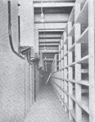
| Fig. 7.--View in Low Tension Bus Room, Bus Side. |
| |||
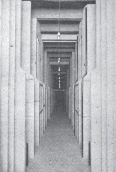
| Fig. 8.--View in Low Tension Bus Room, Between Busses. |
The outgoing generator leads from the oil switches go to cable heads supported and isolated in a substantial manner, directly under the floor supporting the switches. Here change is made to three-conductor cables, two being required for each generator. They are paper insulated and lead covered, having outside of the lead a spiraled steel ribbon armor imbedded in and covered with jute.
Thus far the electrical construction is of conventional form, but arranged and installed with due regard for ease of inspection, the isolation of power circuits, and the logical grouping of apparatus.
The necessity for the location underground of the three-conductor generator cables and the various low voltage control circuits leading to the distributing station, presented new problems which were met in the following manner. A tunnel approximately nine feet square with arched roof was cut through the rock. This tunnel starts on a level with the main floor of the generating station, extends through the rear wall and rises at an angle of thirty degrees until it has passed under the main water conduits. For this portion of the distance it accommodates the two thirty-inch penstocks for the exciter turbines. After passing under the main conduits it rises at an angle of sixty degrees and opens into a manhole halfway up the bluff to the distributing station. The difficulties were to support the three-conductor power cables and yet to isolate them and to provide for their easy drawing both in and out of the ducts.
| |||
| Fig. 9.--Low Tension Switch Room. |
| |||
| Fig. 10.--View in Transformer Room. |
After the tunnel was cut through it was lined with brick, an offset being left in each side wall of sufficient height to accommodate ten vertical courses of tile ducts, secured in place by steel ties and a facing of concrete. At frequent intervals in each duct course a tile was omitted. In the openings so formed iron clamps with wooden bushings for gripping the cables were secured by bolts to the rock wall. The requirement for such support will be seen when it is understood that a generator cable weighs thirteen pounds per foot, and for the length of the tunnel exerts a downward force of over a ton.
The control cables for the operation of the governors, field switches, rheostats, oil switches, exciters and pen-stock valves are carried in iron conduits secured by hangers to the roof of the tunnel. These conduits are interrupted at intervals to allow the admission of a wood bushing which clamps the cable and bears against the end of the conduit to assist in supporting the cable. The exciter penstocks are located on the floor of the tunnel and support a stairway which affords easy access.
| |||
| Fig. 11.--A Transformer Compartment. |
| |||
| Fig. 12.--High Tension Busses and Line Outlets. |
The tunnel construction practically equals in its efficacy the standard underground tile system. The present tunnel will accommodate the necessary cables for six units and extra cables for two units to he used in case of emergency. Two other cable tunnels will be required for the complete plant.
After leaving the manhole at the terminus of the cable tunnel, the cables are carried in three groups of tile ducts buried in the ground, the two outside ones being for power cables, and the inner one for control cables. The construction is of the standard form, though somewhat involved by several curves due to the contour of the ground, and the different relations of cables in the manhole and duct systems.
From the duct courses the cables are taken into a distributing manhole at the front of the distributing station. Both this manhole and the one at the terminus of the cable tunnel have separate chambers for the control and power circuits. Manholes allow of a straight passage of the cable through them, and reinforced concrete shelves of construction similar to that described in the generating station furnish both support and isolation for the cables and splices.
| |||
| Fig. 13.--High Tension Oil Circuit Breaker Compartment. |
| |||
| Fig. 14.--Terminal, Relay, and Recording Instrument Boards, Switchboard Section. |
From the distributing manhole any generator cable may be drawn through a manhole and duct system along the front wall of the distributing station, and connected to any unit in the station.
The distributing station arrangement cannot but he regarded as both novel and unique, and a few of the considerations which have led to its design, may be of interest. In the first place it was impossible to comprehend all of the conditions which might arise in the distribution and utilization of 200,000 horse-power. Unlike the generating station with its similar units, the distributing station would undoubtedly be required to provide for the delivery of power both at generator voltage for use in the immediate vicinity, and also at voltages higher than that of the generator for long distance transmissions.
| |||
| Fig. 15.--Control Room. |
| |||
| Fig. 16.--View Along Tower Lines. |
The delivery of power at generator voltage, however, would require but a comparatively small amount of space for the necessary busses, switches and lightning arresters, while the delivery of power at higher voltages would require. besides switches and busses for the generator voltage, a considerable amount of space for transformers and high voltage equipment. In fact, the required ground space for a high voltage unit is over ten times that for a unit of the same capacity at generator voltage.
It was thus evidently impracticable to commence the construction of this building at one end, as was possible with the generating station, since the combination of low and high voltage unit spaces as they might be required would probably lead to either a very irregular building, or else one with considerable waste space. The assumption was therefore made that the output of six generators was the maximum amount that would be required for delivery at generator voltage. This capacity required such a length of bus for switch connections as might very properly be devoted in the length of the building to the switchboard and control equipment. Likewise the width of building required for the switchboard equipment in addition to that required for the low voltage units corresponded very closely to the width required for high voltage units. Consequently the switchboard section is located in the centre of the building with switches and busses of low voltage units in front of it, and their lightning arrester and selective switch equipment in the rear, the outgoing low voltage feeders passing under-ground beneath the switchboard section. The low voltage switches and busses of the high voltage units occupy the same position relative to their respective transformer sections as do those of the low voltage units to the switchboard section. This arrangement allows a continuous low voltage bus and switch room, also a continuous high voltage bus and switch room, and subdivides only the high voltage transformer equipment, which division possesses some considerable advantage.
| |||
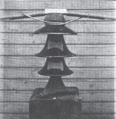
| Fig. 17.--A Single Insulator Tie. |
| |||
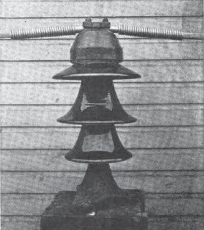
| Fig. 18.--Insulator With Clamp. |
The distributing station is then the locus of the control and distribution of all power from the generating station. With its present dimensions it will accommodate besides the switchboard and control apparatus for the complete development, the equipment for handling the output of fourteen generators, provided that six deliver power directly to the transmission lines. The extensions to the building will be on each end and entirely for high voltage units.
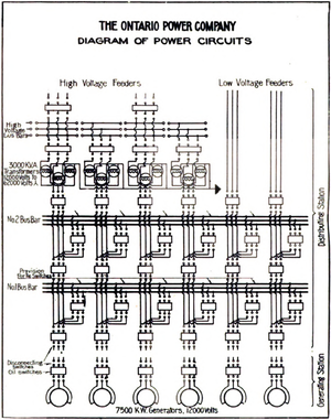
That arrangement of the power circuits which would be best adapted to the character and future requirements of the plants was open to equally as much doubt as was the design of the building itself. The arrangement which has been adopted is shown in the accompanying diagram of power circuits. It is believed that it possesses a flexibility sufficient to meet any requirements that may arise.
It will be noted that there are two busses for low volt age and one for high voltage. All have links or tie switches to break their continuity on each side of their junction with a unit. Generators may be parallelled on either of the low voltage busses, and when so operated may supply the high voltage bus through the transformers. When operation in this manner has been effected the generators may be disconnected from the low voltage busses. The cross-connection of generators to either low voltage feeders or transformer units, is also possible with the arrangement adopted. By opening either the tie switches in the bus bars or the selector switches connecting to them, the station may be operated as a number of individual power plants.
The system is necessarily a unit one in the arrangement of its wiring, switches, transformers, and other apparatus from the generators through to the outgoing feeders, and is such as is best adapted to a trunk station of this character where there are only a comparatively few ma in feeders All switches feeding busses, both high and low voltage are equipped with overload and reverse current relays. Switches taking current from busses have overload and time limit relays. As previously stated the switch in the generating station can be opened by control at that point, but it can be closed only by the operator at the distributing station. When working automatically it opens in conjunction with the first switch in the distributing station.
With the ability to control switches from a distance and with the busses, switches, transformers and other apparatus located in the order of their sequence in the circuit connections, the distributing station houses a collection of symmetrical units with the various apparatus and constructions for each placed in regular order, and either isolated by barrier walls or separated from each other by being in different rooms, according to the relative risks. The result is a harmony that cannot but be of advantage in the operation of the station, and a segregation that is of value in preventing interruptions of the service, both of which have been attained with an expenditure that is fairly proportionate to the results, and a simplicity that is apparent when seen, though difficult to describe.
The generator circuits entering the low voltage bus room and the feeder circuits leaving it are single conductor cables, the change having been made from three-conductor cables, in a manhole for each unit without the station wall. The conductors, insulated with treated cambric, are mounted on insulators and with their series transformers for the actuation of instruments and relays are isolated by vertical concrete barriers.
The strap copper busses are mounted in a horizontal position on the outer sides of two concrete division walls extending from the floor to the ceiling of the room. They are supported in and isolated by a structure quite similar to that described for the generator leads in the generating station. All connections to and from the busses pass through porcelain bushings into the space between the two main division walls, and thence extend vertically to the switches in the room above. They also are separated by concrete barriers, there being no two cables in any one compartment. Potential transformers for use with instruments are placed within the same central space, and are isolated with barriers of alberene stone, the front of their compartments being closed by asbestos doors.
The use of concrete for the almost entire construction of a bus structure is somewhat of an innovation, and the success obtained with it assures the continuation of its use. It is not only strong, easily erected and economical of space, but furnishes one of the best fire resisting mediums, and is comparatively inexpensive.
In the low voltage switch room the oil switches are arranged in two parallel rows and separated into their unit groups. They are of the plunger type, actuated by direct current magnets. Knife switches in both incoming and outgoing leads, permit of their complete and assured disconnection from all circuits for necessary manipulation or adjustment.
The single conductor leads from the bus room to the low voltage feeders, and transformer units have the standard cambric insulation, but are lead covered and are carried underground in ducts.
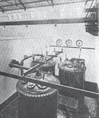
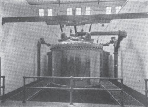
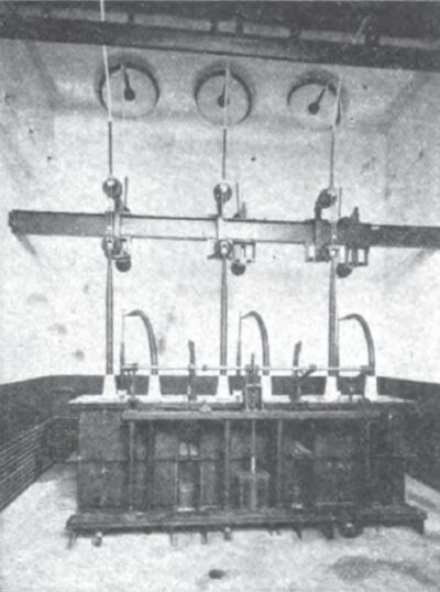
In the transformer rooms, only one of which is at present completed, are located both the transformers, and the oil insulated choke coils, for their protection. The three transformers of a unit are of the oil insulated, water cooled type, connected in delta on the low voltage and in star with centre grounded on the high voltage side. The secondary potential of each transformer is 36,000 volts, and as connected the resultant line voltage is approximately 62,000. Each transformer has a normal capacity of 3,000 K. V. A., and weighs, complete with oil and case, approximately 50 tons.
Each transformer case is cylindrical in form, and the three constituting a unit, are arranged in a triangular group in a pit six feet below the level of the main floor.
 |
| Fig. 19.--Diagram of Power Circuits. |
Strong barrier walls rising to an elevation several feet above the tops of the transformer cases isolate each group of transformers and choke coils from adjacent similar groups. A lower wall separates each transformer group from its corresponding bank of choke coils. The track space extending through the building along the open side of the transformer pits provides room for assembly or repairs.
Besides the protection given to the groups of transformers by the barrier walls, each transformer case is so strongly constructed that in case of short circuits or combustion within it the expanding oil and gases will find relief to the sewer through an eight inch outlet pipe, without giving rise to pressure exceeding the strength of the case. While there is but little chance of continued combustion within a closed case of this type, cold oil may he admitted from the supply pipe at the bottom to flood the transformer if required.
A travelling crane spans the room, and will handle any choke coil or transformer without interference with the operation of other units.
The necessary oil and water piping with its numerous valves, is carried in a space provided between the foundations underneath the floor of the pits.
The high voltage wiring from the transformers is insulated with treated cambric and further protected by a braided fire-proof covering of asbestos. It is supported on large porcelain insulators in the upper part of the transformer pits, the proper connections to the transformers being made through terminals issuing from the tops of their cases. The three outgoing leads, after con fleeting with the choke coils, pass into the high voltage room through insulating bushings set in the centres of circular wall panels. These panels are composed of two half-inch sheets of a fire-resisting, insulating composition.
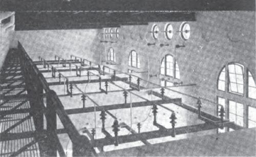
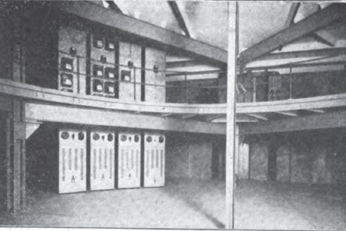
In the high voltage room the switches and series transformers are on the floor and the bus-bars overhead. The latter are composed of copper pipe wrapped with treated cambric and asbestos braid, and are supported mainly by their tie switches which are mounted on the tops of high masonry walls which separate the units.
The wiring is done in the same manner as in the transformer room, there being a clearance of several feet between wires, but no other protection than distance and the insulation on the wire.
The construction and action of the high voltage switch ;s like that of the low voltage one, but it is considerably 1,rger because of the longer break and greater insulating distances required for the higher voltage. The oil is in large steel tanks, approximately five hundred gallons being required for a switch. Oil piping for the switches and control wiring for their actuation are carried underneath the floor.
In every alternate compartment are the switches and series transformers of feeder circuits, there being at present but half as many feeders as transformer units. Each wire of an outgoing feeder passes out of the building through an insulating bushing supported in the centre of a double glass panel set in an opening in the wall.
That portion of the high voltage bay which corresponds in length to the switchboard section is shut off from the high voltage busses, and serves as an outlet for the low voltage feeders and their accessory devices. In this room is also a secondary low voltage bus for the switching of power to the transformers supplying the light and power service to the plant.
The outlets in the exterior wall of the building for both high and low voltage feeders have their insulation protected from the weather by an overhanging hood.
Horn gap lightning arresters of generous proportions and with graded gaps and resistances are located in the rear of the station for the protection of high voltage feeders.
Low voltage circuits are at present carried on wood poles, the details of the construction embracing no particularly new features.
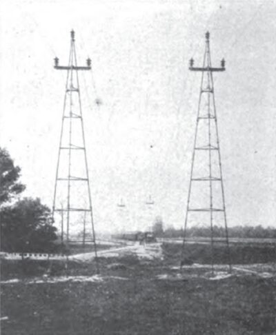
The high voltage circuits are in duplicate, and are carried on steel towers placed usually along a private right-of-way. The towers have a triangular base, tubular legs, and carry but the three wires of a circuit. A clearance of 30 feet is everywhere preserved between circuits. The construction is made especially strong with concrete anchorages, and the liberal use of guys at angles and crossings. The insulators are massive, and are mounted on steel pins. The transmission cables are of aluminum one and one-eighth inches in diameter, secured by ties or clamps as conditions require, and protected at the insulators against arcs by a serving of aluminum wire.
Having now traced the power courses from the generators through to the transmission lines, attention naturally turns to the control and measurement of the power.
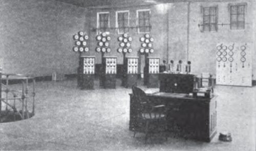
The control room is located on the top floor of the switchboard section, at the most advantageous position for the observation of the apparatus in the distributing station. Control pedestals, corresponding in number to generator units, containing operating switches and pilot lamps, with indicating instrument stands directly back of them, arc arranged in an approximate semi-circle around the room. The line is broken only at the centre to permit of the feeder control panels, located at the back of the room, being visible to the operator. The semi-circular arrangement allows ample clearance between units for their distinguishment, and also enables the operator to see every instrument from any position within the control area.
Each instrument stand has mounted upon it a voltmeter, ammeter, wattmeter, power-factor indicator, frequency indicator and synchroscope; also three ammeters connected in the leads to the transformers.
A control pedestal contains, besides the small switches for the control of oil circuit breakers, push buttons for opening and closing the generator field switch, a controller for the rheostat face-plate and a controller for varying the speed of the turbine through the medium of the governor. A diagram of circuits on the face of each pedestal, in which arc placed pilot lamps from oil switches, enables the operator to comprehend at a glance his circuit connections.
Each feeder control panel carries the switches and pilot lamps necessary for the control of the oil circuit breakers in the duplicate feeders and three ammeters for each feeder circuit.
Opposite the semi-circle of generator and feeder controls arc two service boards, one on each side of the entrance to the room. One of the boards contains the switches and instruments required for the distribution of alternating current at 220 volts for light and power purposes in the building; also the control for the oil circuit breakers located in the low voltage service bus. The other board contains the switches and instruments requisite for the distribution of 250 volt direct current (derived at present from one of the exciters) for lighting and control purposes. There is also a panel nil this board for the control of a storage battery which serves as a relay for the 250 volt exciter control current.
On the three floors beneath the control room, arranged in the same semi-circular manner, there are in order the recording instrument boards, terminal and relay panels and assembly racks for control and instrument wires. The room containing the latter is in the basement, and. besides accommodating the wires, contains a cell for a sixty ampere-hour storage battery, and also serves as a distributing point for all oil, water and steam piping.
The control and instrument wires, grouped into cables according to the character of service, come into the assembly room on separate shelves for each unit from channels which are entirely isolated from the power apparatus. Here they rise to the terminal boards where there is a terminal and fuse for every wire. These terminal boards and the similar ones in the generating station furnish definite points for the detection of trouble in any control or instrument circuit. From the terminals the wires go to the switch relays or recording instruments, or to controls and instruments in the control room.
The graphic recording instruments are of a new type and comprise voltmeters, ammeters, wattmeters, and frequency and power-factor indicators. They are so connected in the low voltage circuits that there is a continuous record of each generator as well as of the demands of any set of feeders.
In the control room the chief operator's position is in the centre where, at his desk, he may observe, through his instruments, every electrical occurrence and direct his assistants as required. He has his own private telephone system running to all the rooms in the building, and also has direct connection with the telephones along the transmission lines. He may communicate with the generating station either by telephone or telautograph, the latter being almost exclusively used because of its unmistakable records.
While unusual for the control operator to be away from the sound and sight of his moving machinery, it is believed that the design which necessitated it has been carried out in such a manner that the separation may prove of distinct advantage.
Of the principal electrical equipment of the plant, the wires and cables have been furnished by the Standard Underground Cable Company, Pirelli and Company, of Italy, and the Northern Aluminum Company, and the apparatus by the Westinghouse Electric and Manufacturing Company.
The electrical design of the plant has been in the charge of the writer under the direction of the Engineers, Messrs. L. L. and P. N. Nunn, and with the aid of an able corps of assistants, amongst which stand out most prominently the names of Mr. Paul Cheever and Mr. J. A Brundige.
(1) For complete general description of the Ontario Power Company, see paper by Mr. P. N. Nunn. Engineer, presented at the twenty-second annual convention of the American Institute of Electrical Engineers, Asheville, North Carolina, June 19-23, 1905.
