[Trade Journal]
Publication: Electrical World and Engineer
New York, NY, United States
vol. 39, no. 8, p. 333-334, col. 1-2
The Dalles, Oregon, Transmission Plant.
By ARTHUR SEUFERT.
THE beginning of the corporation which recently completed The Dalles 20,000-volt transmission plant goes back to Sept. 11, 1883, when the Wasco Warehouse Company was formed for the purpose of engaging in the wool business and in forwarding and storing general merchandise. In 1890 another corporation known as The Dalles Electric Light & Power Company, was formed for the purpose of furnishing light and power. In 1901 the above corporations were consolidated into the Wasco Warehouse Milling Company, having a capital stock of $300,000, and composed of leading business men and bankers. It having been decided to build a flouring mill at The Dalles of a capacity of 700 barrels a day, the question arose as to what to use for power. It was quickly decided that electric power was the most feasible, as within a few miles there are many undeveloped waterfalls, among which may be mentioned one at Hood River, 22 miles west; another at Klickatat River in Washington, 20 miles west; the Celilo Falls in the Columbia River, with a fall of 34 ft., about 12 miles east; the Des Chutes River, 18 miles east, and the White River, a branch of Des Chutes River, 27 miles south. After careful examination of all, the latter was decided to offer the most advantages, including lowest cost for development, and in 1901 a contract was let to the Pacific Bridge Company, of Portland, to develop the power and build the generating plant. Work was started in August, 1901, and the plant was to be completed before Nov. 15, 1901, but through unforeseen delays it was not ready for operation until Jan. 5, 1902.
| |||
| Fig. 1.White River Falls. |
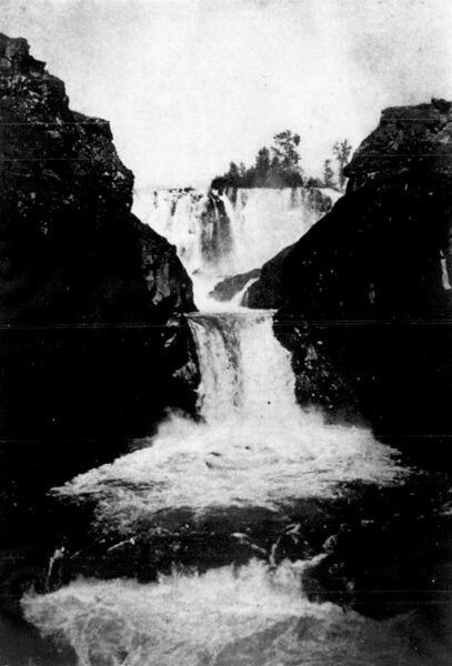
The plant is situated as a bird flies, 27 miles south of The Dalles at White River Falls in Wasco County, Oregon. There are two falls in the river at the head of the works, and the power station, which is of stone, 30 by 60 ft., is at the bottom of the second fall. The plant is placed 10 ft. above the level of the river, and utilizes a head of 131 ft., the 10 ft. insuring there will be no interference through freshets in the river. At the head of the falls there is a concrete dam 8 ft. high, from which the water is carried in a wooden flume 54 inches in diameter and 1200 ft. long laid with one foot fall to a hundred, and delivering a head of 119 ft. at the waterwheel pit. There are at present three waterwheels, two of which are direct connected to two three-phase 500-kw, 2300-volt generators, operating at 60 cycles, and of a current capacity of 126 amperes each. The other wheel is direct connected to a 30-kw exciter. This wheel is also in reserve for another generating machine in case business requires its output. The waterwheels were made by the Knight Waterwheel Company, of Sudder Creek, Calif., and the electrical apparatus by the General Electric Company. The current passes through three 400-kw step-up transformers of the air-blast type, in which its voltage is raised to 22,000. The transformers are connected in delta, and are cooled by air furnished by a blower, a second blower being held in reserve. There are three oil switches.
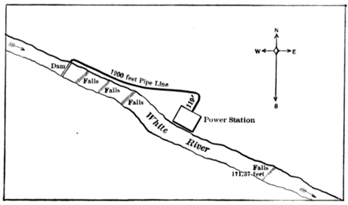 |
| Fig, 2.Map Showing Location of Plant. |
The line is 27 miles long, and of No. 6 B. & S., bare copper wire on glass insulators. The conductors are transposed every mile. The main line poles are 35 ft. high, and those in The Dalles 60 ft. high, all being of cedar with 8-inch tops. There is a telephone line 6 ft. below the high-potential line, transposed every five poles. No inductive effect whatever has been noticed in telephone transmission.
| |||
| Fig, 3.Sub-Station, the Dalles. |
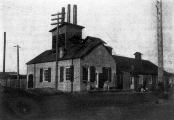
The sub-station at The Dalles is built of brick, the dimensions being 27 by 45 ft. It contains three transformers, each of 375 kw, air- cooled under a pressure of 54 ounce by a blower, a second blower being held in reserve. The voltage is here reduced to r1oo for distribution. There is also one 35-light constant-current 6.6-ampere transformer. The high-potential switches are of the oil-break type, mounted in a brick vault. There are also two oil-break switches on the low-potential circuit.
The 35-light transformer is for street lighting, the arc lamps used being of the enclosed type and of 1200 cp, all connected in series. The lamp takes about 72 volts at the arc.
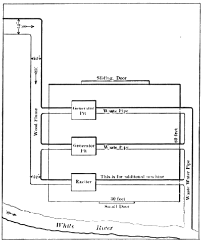 |
| Fig. 4.General Plan Ol the Power House. |
The flouring mill has two induction motors, one of 200 hp and one of 50 hp, operating at 1040 volts. The larger motor runs the mill, and the smaller one operates the elevator. The city lighting circuit has a voltage 1040 volts, which is stepped down to 104 volts for in- candescent lighting.
The plant so far has given perfect satisfaction, and from all appearances will continue doing so. There is at present a surplus of 700 hp. Fig. 1 shows the White River Falls. The generating station is on the left side of the view, but does not show in the picture, as it is situated considerably below. Fig. 3 shows the sub-station at the Dalles. The chimney of the old steam plant which had to give way to the new one, is shown to the left.
