[Trade Journal]
Publication: Electrical World and Engineer
New York, NY, United States
vol. 39, no. 12, p. 503-507, col. 1-2
The Transmission System of the Compania Explotadora De San Ildefonso of the City of MexicolI.
By STEPHEN Q. HAYES.
TRANSMISSION LINES AND ATTACHMENTS.
ALL of the 20,000-volt, high-tension transmission lines are protected by means of Westinghouse Lightning arresters, shown in Figs. 20-22. This part of the installation was very carefully planned, owing to the number and violence of the electric discharges during the rainy season, lasting four or five months of the year.
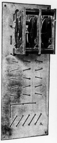
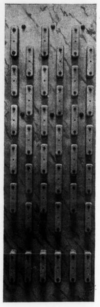
For circuits of more than 15,000 volts the arrester is mounted upon a marble panel. The non-arcing metal cylinders are held in porcelain holders on the front of the marble and the choke coils are mounted upon the back, being secured to marble partitions supported from the upper part of the panel. This construction is handsome in appearance, affords high insulating qualities, and is fireproof. The connections of the choke coils and non-arcing cylinders that go to make up this arrester are similar to those shown in Fig. 22, which illustrates a 15,000-volt, three-phase circuit.
| |||
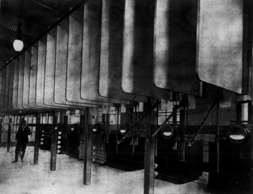
| Fig. 19.High-Tension Room at Fernandez Leal. |
The two three-wire transmission lines running to Madin from the power houses along the Monte Alto River and the Tlalnepantla River are supported on metal poles 29 ft. high, made in three sections of, respectively, 5, 4 and 3 inches diameter. The weight of these poles is 385 lbs. They are stationed 130 ft. apart, and are planted 5 ft. directly in the earth without the necessity of masonry. Those that are placed in the damp valleys are encased in a cylindrical block of hydraulic cement, 2 ft. in diameter and 6-1/2 ft. deep.
The wires are placed on two wooden cross arms on a summit of two equilateral triangles 2 ft. on the side symmetrically placed with reference to the axis of the poles. These cross-arms are fixed to the poles by means of U-shaped bridles, which present to the pole a large surface of contact. The supports of the insulators are eucalyptus wood pins boiled in paraffine. The insulators themselves are triple petticoat insulators, such as in Fig. 23, which have been tested at 40,000 volts before being placed in position; and the wires of the line are covered with a weather-proof composition. The two three-wire lines running from Madin to the City of Mexico, which transmit the entire output of the power stations, were to have been placed like these foregoing ones on the same pole. But several insulators, mischievously broken at the time of erection, showed the advisability of having the two lines entirely distinct and a new pole line was built. The poles are of Texas red wood, 32 ft. in height, of which sections at the bottom and top are squares, respectively, 9 and 5 inches on the side.
| |||
| Fig. 20.Front 30,000-Vol Lightning Arrester. |
| |||
| Fig. 21.Rear 30,000-Volt Lightning Arrester |
The diverging point of the two pole lines is indicated in Fig. 24 The three wires of the existing transmission lines were transferred in sections and placed on the wooden poles, at the vertices of equilateral triangles 2 ft. on a side. One of the wires is carried at the top of the poles by means of a glass triple petticoat insulator of the type employed with success on the 40,000-volt Provo transmission line. This insulator, shown in Fig. 25, is supported by a eucalyptus wood pin 9g inches high, boiled in paraffine. The other two wires are placed in the same way on a wooden cross-arm 31 inches long. The new transmission line from Madin to the City of Mexico is 10 miles long, while the old one was 834 miles. As the action of the reverse circuit breakers in the City of Mexico depends to a certain extent on the resistance of the two lines, it was necessary to use a larger wire on the new line than on the old one.
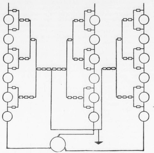 |
| Fig. 22.Connections 15,000-Volt Lightning Arrester. |
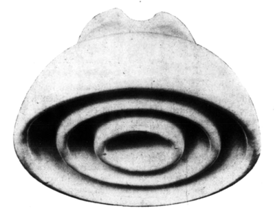 |
| Fig. 23.Porcelain Triple Petticoat Insulator. |
| |||
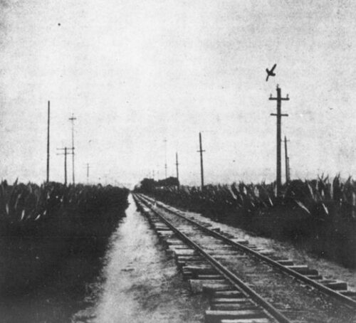
| Fig. 24.Lines at Madin. |
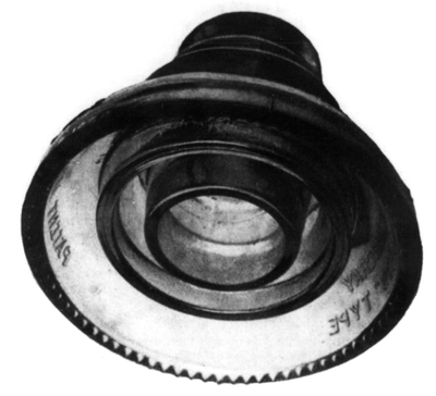 |
| Fig. 25.Glass Triple Petticoat Insulator |
 |
| Fig. 26.Diagram of Connections Madin Junction. |
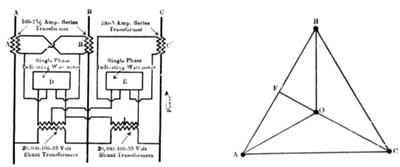 |
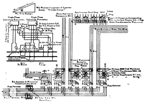
| Fig. 27.Diagram of Wattmeter Connections. |
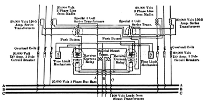 |
| Fig. 28.Diagram of Connections-Reverse Current Breakers. |
The high-tension junction switchboard at Madin, with its unique arrangement of wattmeters and synchronizing apparatus, is of particular interest. It will be noticed (Fig. 26) that either or both of the lines from the Monte Alto River, as well as either or both of the lines from the Tlalnepantla, can be connected with either or both of the lines running to the City of Mexico. The method of synchronizing these various lines before throwing them together is similar to that described for the Chiluca generating station. The synchronizing apparatus of lamps and plugs is connected across similar terminals of the 100-volt side of the 20,000-100-volt shunt transformers fed from the lines running to Madin. These shunt transformers, with the series transformers shown, are also used for the main watt- meters which indicate the amount of power received at Madin over each of the four transmission lines. This high-tension board is shown in Fig. 12, last issue.
The indicating wattmeters in the lines running to the City of Mexico have their current coils connected to the same series trans- formers as the ammeter, and their voltage coils are connected to the middle of six-point voltmeter receptacles, so that a voltage in phase with the current (if the power factor were 100 per cent) or one at right angles to it, can be impressed on the wattmeter. In the former case it will indicate that component of the apparent energy, Wa, which is in phase with the voltage, or, in other words, the true energy, Wt. In the latter case it will indicate that wattless component of the apparent energy which is at right angles to the volt- age. Calling this, for the sake of brevity, the wattless energy, Ww, it can readily be shown that the relative magnitude and phase relationship of Wa, Wt and Ww is that indicated by the triangle in Fig. 26. As the apparent energy Wa is in phase with the current, and the true energy Wt is in phase with the voltage, the phase angle between the two is the angle of phase displacement between current and voltage.
From the triangle it is seen at once that tan ф=Ww/Wt. In other words, by comparing the reading of the wattmeter with the voltmeter plug in the two different positions, the angle of phase displacement can be readily figured out, and the angle is one of lag or lead, according as the ratio of Ww to Wt is positive or negative.
As in all of these connections two single-phase wattmeters are used on a three-phase circuit, it may be well to give a short description of their operation. For description, as well as that of the operation of the reverse current-circuit breaker given later, the writer is indebted to Mr. Conrad, of the Westinghouse Electric & Manufacturing Company.
Fig. 27 shows the connection of the two single-phase wattmeters on the three-phase circuits of this plant, as well as the phase relation of the different currents and voltages in the circuit. By this arrangement it is possible to connect two single-phase indicating or integrating wattmeters in a three-phase circuit so that with a balanced load, each wattmeter will indicate one-half of the total energy supplied, irrespective of the power factor of the circuit; and in all conditions of an unbalanced load, the sum of the readings of the meters will represent the total energy of the three-phase circuit in which they are connected.
Referring to Fig. 27, A, B and C are the three mires of the circuit, D and E are two wattmeters of the usual construction, giving readings proportional to the product of the current, the voltage and the cosine of the angle of phase difference between them. The shunt windings of these meters are intended for use on a 100-volt circuit, and are connected to the low-tension side of the 20,000-100-50-volt shunt transformers. The series coils of these meters are wound for a full-load current of 5 amperes. A and B are series transformers with 2-1/2-ampere secondaries, and C is a series transformer with a 5-ampere secondary, 2-1/2 and 5 amperes being the secondary cur- rent with full-load current in the primary.
Secondary coils of the transformers A and B are connected in parallel and supply current to the series coil of the meter D. The transformer C is connected to the series coil of meter E. Thus the current in the series coil of meter D will be proportional to the vectorial sum of the currents in the wires A and B, while that in meter E will be proportional to the current in the wire C. The shunt circuit of meter D is connected to the secondary side of a 20,000-100-volt shunt transformer, whose primary connections go to the lines A and B, having the series transformers which are connected to this meter. The shunt circuit of meter E is connected on one side to the secondary of a 20,000-100-volt shunt transformer whose primary is connected across the line B and C, and the other end of the shunt circuit of meter E goes to the middle pointthe 50-volt loopof the transformer connected across A and B.
Referring to that part of Fig. 27 which shows the diagram of phase relation of the current and voltages in the three-phase circuit, the line OA represents the current in the wire A, the line OB the current in the wire B and the line OC the current in wire C. The meter D receives its series current from the two transformers A and B. This current is, therefore, equal to the resultant of the lines AO and OB, and is proportional to, and in phase with, AB. The voltage for the shunt of meter D being taken from the secondary of a transformer whose primary is across AB, is, therefore, in phase with the current AB.
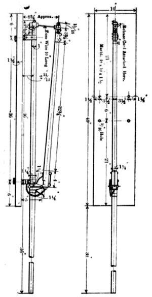
| |||
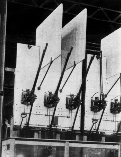
| Fig. 29.3-Pole, 20,000-Volt Circuit Breaker. |
The series current for the meter E being proportional to that in the wire C, is equal to and in phase with the line OC. The shunt connections of this meter are taken from that secondary terminal of the shunt transformer connected from C to B, corresponding to primary terminal C, and the other end being connected to the middle point of a shunt transformer whose primary is across AB. In this way the shunt current of meter E will be proportional to a line drawn from C to the middle point F of line AB, and (assuming in this case a non-inductive load) this voltage line CF will be in phase with the current OC.
 |
| Fig. 30.Fused Circuit-Breaker. |
The scales of the meters are marked to indicate the capacity corresponding to the ratios of the transformers through which the meters are connected to the circuit. Thus if we assume a 20,000-volt circuit and series transformers having a ratio of 100 5-amperes, the meter would indicate 2000 kw, this being the product of that current and voltage when a current of 5 amperes is passed through its series coil with a pressure of 100 volts on its shunt coil.
This applies particularly to meter E, as meter D is fed from two transformers, each with 2-1/2-ampere secondaries; but the two being in multiple produce the same result practically as 5 amperes or actually 5 X cos.30 degs. equals 5 X .866 equals 4.33 amperes. As will be explained later, this is exactly the current wanted in this meter. If any load on the circuit is assumed it will be found that the meters will indicate this load directly. Thus at the full load of 100 amperes per wire at 20,000 volts between wires, the energy in the three-phase circuit will be current X voltage X V3, or 100 X 20,000 X 1.732 = 3464 kw.
Referring again to the diagram of phase relations in Fig. 27, 100 amperes in each line will give 2-1/2 amperes in the secondaries of transformers A and B and 5 amperes in C. The current in the series coil of meter D will be equal to 2% amperes in the direction of AO and 2% amperes in the direction of OB, which is equal to 4.33 amperes in the direction of AB. The shunt of .this meter being connected to a transformer across AB will have a voltage of 100 on it, and multiplying the current by the ratio of the series transformers
100 / (2-1/2 + 2-1/2) = 20 by the voltage, and by the ration of the shunt transformer (20,000/100 = 200), the wattmeter reading of D = 4.33 X 20 X 100 X 220 = 1732 kw, or half of the energy.
The meter E, receiving its series current from the transformer C, will have 5 amperes in the direction OC in its series coil. As this shunt connection is equivalent to the line CF, as previously explained, this is equal to the voltage CB or CA multiplied by the cosine of the angle between CF and CB or CA. When CB equals 100 volts CA will equal 100 X cos 30 degs., or 86.6 volts. To get the wattmeter reading, we multiply the current by the series transformer ratio, 100/5 or 20 X voltage X ratio of shunt transformer (20,000/100 = 200), and we have the wattmeter reading of E=5 X 20 X 86.6X 200 = 1732 kw, or half of the total energy. For any other power factor than unity the effect on each wattmeter would be to multiply its reading by the cosine of the angle of phase displacement, and it will be found that each meter still reads one-half of the total energy of the circuit.
Another point of interest in connection with the switchboard equipment of the Compania Explotadora transmission system is the pair of three-pole 20,000-volt, 150-ampere circuit breakers with time limit and reverse current attachments which are installed at the terminals of the two 20,000-volt, three-phase lines where they enter the La Veronica receiving station.
Fig. 29 is reproduced from a photograph of these circuit breakers. As shown on this photograph, each three-pole breaker consists of three single-pole breakers, each mounted on a marble slab with one handle for closing all three breakers at the same time. No mechanical device is supplied for tripping these breakers together as they may be operated from a push button or the relays in multiple with each other, and either of which can trip the breaker. Below the main marble panels of the breaker are smaller panels for mounting the time limit device with its system of shafts and levers. Below this is placed the polyphase relay and the push button, the series and shunt transformers being mounted on the framework on the back of the circuit breaker. Between each pole of the breaker is a large marble barrier to prevent the arc from passing from one pole to an- other. Fig. 29 shows the diagram of connections for these reverse current circuit breakers. The relay consists of a polyphase watt-meter connected in the circuits in the usual manner. In place of the usual counting train, a contact operates the tripping coil on the circuit breaker. When the flow of energy is in the normal direction, the contact in the re- lay is held open, but should the direction of flow be reversed, the movable part in the relay will turn and close the contact, completing through the tripping coil a local circuit that operates the breakers.
The object of this device is to open a circuit whenever the direction of the flow of energy in this circuit has been reversed. This is accomplished by means of an ordinary circuit breaker, which in addition to the series tripping coil has a tripping coil wound with fine wire, and adapted to operate on a circuit of about 100 volts. This circuit is closed by a relay. On circuit breakers with time limit attachment, the mag net of the time limit is connected in place of the tripping coil.
he circuit breakers used in this installation are fed by two lines in parallel and required some additional apparatus. Should one of these lines be short circuited and cause the circuit breaker at the generator end to open, this line would still be fed from the sub-station end by the remaining line, which is in parallel with it. The result of this would be that the energy, instead of flowing over the line to the sub-station, would flow in an opposite direction, that is, from the sub-station to the line; but if the current taken by this short-circuited line was very great, it would cause an excessive drop in the other line, and so lower the voltage that the relay and circuit breaker tripping coil would not operate.
To keep the voltage up a special transformer is connected between the relay shunt and the line. This transformer gives, with normal line voltage, about 100 volts on its secondary. If the line voltage should drop to, say, about one-third the normal, the effective secondary voltage would not drop more than about 20 per cent. The primary of this transformer is wound for 100 volts, and connected to the secondary of a standard transformer with a 100-volt secondary.
A series transformer is used which has two primary coils and one secondary coil. Each of the primary coils is connected in series with similar phases of each line through secondaries of standard series transformers to obtain better insulation. This three-wire transformer is so arranged that when the currents in the two lines are in phase there is no current in the secondary; but when they are in opposition, it gives the full secondary current, the amount of which de- pends upon the ratio for which the transformer is wound. By means of this device no current is sent through the relay until one of the lines has been reversed. It is thus possible to make the transformers give a larger secondary current than the relays would stand continuously, thus operating them more positively. The shunts of the relays are connected across the circuit, through the medium of the special shunt transformer, which gives an approximately constant secondary voltage with variable primary voltage. This transformer performs, also, the function of keeping the current and voltage on the relay in phase.
On a long line the inductive drop forms a large part of the total drop, so that with a short circuit we should have a lagging current; and as the operation of the relay depends only on the true watts, the lagging current ordinarily tends to lessen the positive action of the relay. The special shunt transformer, however, gives a secondary voltage leading in phase with respect to the primary voltage. The relay device is so adjusted that it gives its maximum effect with the shunt voltage leading. If an excessive current cause a drop in the line, the secondary voltage will shift and keep in the same phase relation to the series current in the relay. Thus the pull in the relay continues a maximum, even with a large lagging current in the line. The shunt transformer is designed to shift the phase of the voltage in the same proportion as an excessive line current causes an inductive drop in the line.
The function of the time limit on these circuit breakers is to delay for some predetermined length of time the opening of the circuit breaker, so that a momentary overload where the series coil comes into play, or a momentary reversal where the reverse current relay acts, will not open the circuit instantaneously. This time limit can be set to delay the opening of the breaker from one to ten seconds.
From the 20,000-volt, three-phase bus-bars in the La Veronica receiving station, the current passes through 20,000-volt fused circuit breakers to the lowering transformers. Fig. 30 shows an outline of one of these fused circuit breakers, consisting of two stationary contacts on a marble slab with a removable pole. In closing this breaker the upper contact on the pole is hooked over the upper stationary contact on the marble, and with that point as a fulcrum the pole is swung in until its lower jaw makes contact with the bottom block on the marble.
This removable pole comprises a stationary arm and a movable one hinged together. A strong spring tends to separate the arms. This tendency is resisted by the mechanical strength of a piece of aluminum fuse wire which passes through carbon blocks at the ends of the arms. An overload causes this fuse wire to melt and the movable arm flies out, opening the circuit. To renew the fuse the fixed arm is lifted from its contacts and the fuse replaced in safety. To trip this breaker when the fuse has not blown, it is only necessary to pull a cord operating a latch and releasing the fuse wire.
The method of mounting these fused circuit breakers is shown in Fig. 19, on page 503. In the high-tension room at Fernandez Leal, the most striking point of interest is the large wooden shields covered with asbestos, these being used to separate the different breakers.
