[Trade Journal]
Publication: Street Railway Journal
New York, NY, United States
vol. 30, no. 7, p. 256-264, col. 1-2
THE PITTSBURG & BUTLER STREET RAILWAY CO. — II.
BY M. N. BLAKEMORE
Last week an account was published of the power station of the Pittsburg & Butler Street Railway, lately built and equipped with the single-phase system. A description of the remainder of the equipment follows:
SUB-STATIONS
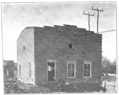
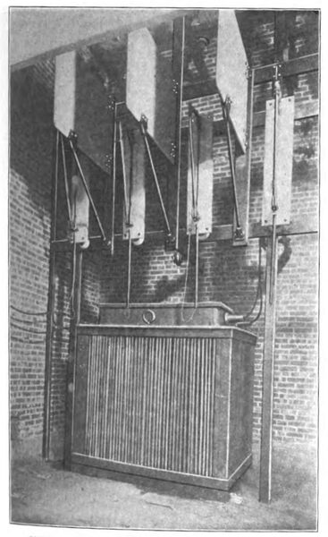
At the present time two static transformer stations have been installed approximately 12 miles apart; one at Mars, which is practically the middle of the system, is shown in the illustration, while the other is at Bryant, near the Pittsburg terminus of the road. In the former station there is mounted one 500-kw oil-insulated, self-cooling transformer, having a ratio of 22,000/6600 volts, but at present operated with a secondary voltage of 3300 volts. In the Bryant station there are two such transformers connected in parallel.
| |||
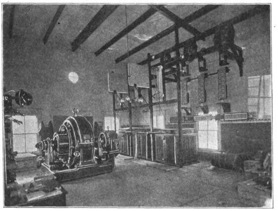
| Interior of Butler Rotary Converter Sub-Station |
The high-tension sides of these transformers are con-trolled by means of fused circuit breakers separated by marble barriers. Low-equivalent lightning arresters and choke coils effectually protect the high-tension lines from lightning discharges. The low-tension sides of the transformers are controlled by means of oil circuit breakers, the same being mounted upon small blue Vermont marble panels supplied with suitable gas-pipe framework.
| |||
| Exterior of Butler Rotary Converter Sub-Station |
The two sub-station buildings are practically identical in construction, with the exception that the one at Bryant, in addition to forming a protection for the static apparatus, also includes a small waiting room. The same style of architecture has been followed in the construction of these sub-stations as is used in the other buildings of the company. The high-tension leads are carried into the sub-stations in the same manner as provided for in the power house.
| |||
| Exterior of Mars Static Sub-Station |
To supply current for the local trolley system in Butler, a rotary converter sub-station has been installed at that place. This station, as shown in the illustrations, includes, in addition to similar high-tension switching and protective apparatus, three 200-kw, 22,000/334-volt transformers. The station also includes one 500-kw, 550-volt direct-current Westinghouse rotary converter, together with a three-panel blue Vermont marble switchboard, which has mounted upon it a full complement of instruments and switches for the control of both the alternating and direct-current sides of the rotary converter, and for two outgoing direct-current feeder circuits. A Wurts tank lightning arrester has been installed to protect the direct-current feeder circuits.
TRANSMISSION AND TROLLEY LINES
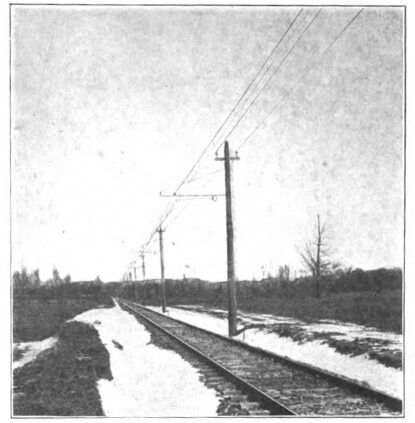
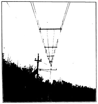
The high-tension circuits are carried from the powerhouse to the transmission lines on Locke insulators mounted on wooden cross-arms securely fastened to two wooden poles, as shown in an engraving in Part I. From a point opposite the power house the transmission lines extend in both directions, the 22,000-volt single-phase line running in one direction and feeding the two static sub-stations at Mars and Bryant, while a three-phase, 22,000-volt feeder extends to Butler for supplying current to the rotary converter at that point. The transmission lines consist of No. 4 hard-drawn bare copper wire, secured to Locke insulators fastened to the tops of the same poles supporting the catenary trolley wires. Wherever the high-tension wires cross telegraph lines or public highways, large wire nettings have been suspended below them to prevent accidents due to the breakage of the high-tension wires.
| |||
| Interior View of Mars Static Sub-Station |
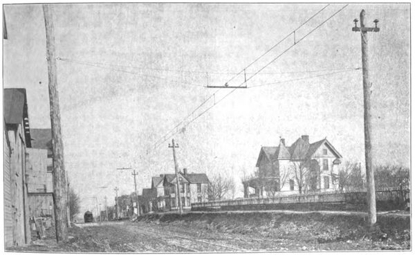
The trolley construction is of the single catenary skirt type and has been designed for a pressure of 6600 volts. The trolley is No. 000 grooved wire, and is suspended from a 7/16-in. seven-strand galvanized steel messenger cable by means of galvanized-iron trolley hangers, spaced approximately 10 ft. apart. These hangers consist of short lengths of pipe threaded at one end and flattened and punched at the other. The threaded end engages in a socket which fits over the threaded portion of two drop-forged steel lugs, which engage in the groove of the trolley wire. The punched end of the hanger is secured to the messenger cable by means of a strap-iron clamp bolted to it.
| |||
| Single Catenary Construction on Tangent |
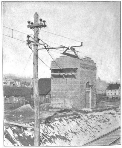
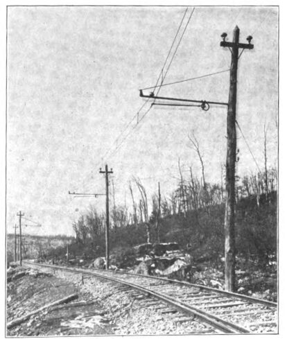
On straight tracks the poles are spaced 120 ft. apart, but on curves this spacing has been reduced in proportion to the degree of curvature. The trolley wire is suspended from standard T-iron bracket arm at an average height of about 19 ft. above the top of the rail. One end of the bracket arm is secured to a 35-ft. chestnut pole by means of iron straps bolted to the bracket and fastened by lag screws to the poles. The other end of the bracket is supported by means of a round iron tension rod passing through the pole and secured to the bracket by a malleable iron lug. The messenger cable is supported from these brackets on porcelain main-line insulators which are cemented upon malleable iron supports arranged to clamp upon the T-iron bracket. The insulators are placed on the bracket arms in such a manner as to give a gradual staggering of the wire from a point 8½ ins. on one side of the center of the track to a point 8½ ins. on the other side at intervals of 1000 ft. or so. This is done to distribute the wear on the sliding contact trolley shoes.
| |||
| Single Catenary Construction on Curve |
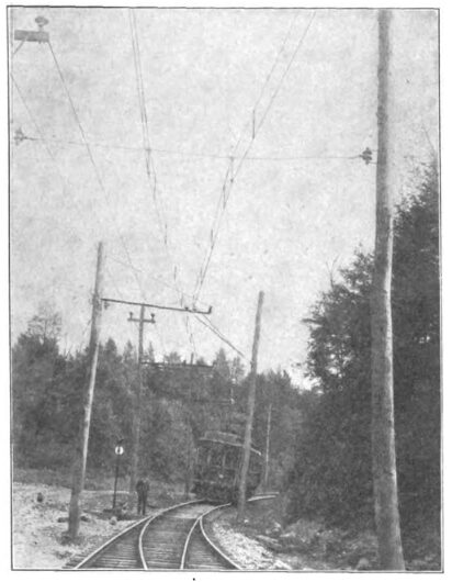
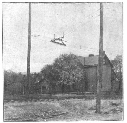
At all points of support on curves, and also at frequent intervals on straight track, a steady strain is used to keep the trolley wire exactly under the messenger cable to prevent swaying owing to the passing of cars. To insure the passing of the sliding contact shoe over turnout switches, a special form of deflector, illustrated on this page, has been provided. This deflector consists of pieces of trolley wire held in place by clamps, the ends of the wires being elevated. The construction is such that the sliding contact trolley shoe is properly diverted from one trolley wire to the other without engaging between the two at the junction of the two wires. At one or two spurs along the road this deflector scheme has been somewhat modified — this is shown in the illustrations — but at regular turnouts the above described method has been followed out.
| |||
| Modified Deflector Scheme at Turnout |
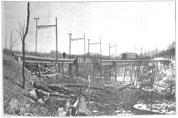
Section-break insulators are used at several points, and that installed at the Butler end of the single-phase line, where it joins the direct-current feeder of the local traction line is shown in an accompanying illustration. A similar insulator is installed at the Pittsburg terminus of the road. When crossing bridges the trolley wire is suspended by means of bracket arms and insulators secured to steel arches erected upon the bridge structures. The high-tension transmission wires are carried on cross-arms, secured to these same arches. At other points along the line, the high-tension wires are carried on the wooden poles as previously explained. In addition to the high-tension wires, the trolley poles also support the wires for the telephone system used in connection with the dispatching of trains. No trouble has been experienced due to static interference from the single-phase line.
ROADBED AND TRACK
In order to adapt its tracks to those of the Pittsburg Railways Company, over which the entrance into Pittsburg is obtained, a gage of 5 ft. 2½ ins. is employed. A. S. C. E. rails weighing 75 lbs. per yard are laid on 7-in. x 8-in. x 8-ft. chestnut ties on 2-ft. centers. The road is single track, except within the city limits, and is stone ballasted through-out to an average depth of 12.ins. Wherever possible the road has been depressed below public highways, but where it crosses the highways on a level, warning posts are erected. Guard rails are used on all curves which exceed 9 degrees, the guard rails being raised about 1 in. above the running rails by means of blocks inserted under the rails.
| |||
| Deflector Scheme at Turnout |
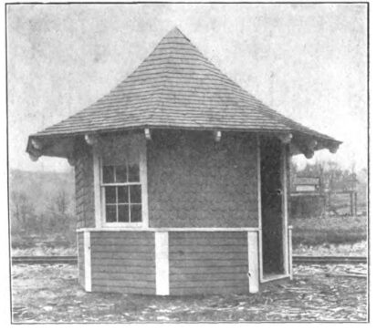
As stated, the road is exceedingly hilly and contains numerous curves, the grade varying from, 3 per cent to 6 per cent, although there is one grade at Etna amounting to 9 1/2 per cent. A considerable portion of the road is over private right of way. In the interurban portion of the road the stops average 2 miles apart, at which locations attractive frame waiting rooms supplied with seats have been erected. One of these is shown on page 260
| |||
| Section Break at Butler |
On the entire road there are three steel and concrete bridges, in addition numerous culverts of substantial character. The viaduct over the Baltimore & Ohio Railroad tracks at Bryant is 297 ft. long and is reached from the north by a 52 per cent grade. In addition to this there is an 8-degree curve at this point. Another bridge crossing the Thorn Creek at Renfrew is 800 ft. long and stands 85 ft. above the water line. The bridge at Butler, spanning the tracks of the Baltimore & Ohio Railroad at that point, is also of interest as containing one girder 115 ft. long, having a depth of 9 ft. The tracks at this point ascend a grade of 6 per cent, containing a 2-degree curve. The economical abutment construction is noticeable in all of the viaducts as well as the good mechanical appearance of the steel work.
ROLLING-STOCK EQUIPMENT
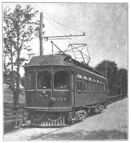
At present the company is operating ten passenger cars, and orders have already been placed for eight additional equipments. The cars were manufactured by the Niles Car & Manufacturing Company, and weigh, complete with electrical equipment, 43 tons. The trucks were supplied by the Standard Motor Truck Company and weigh, each approximately, 17,200 lbs. They are provided with 36-in. rolled steel wheels and 6-in. forged steel axles.
| |||
| Single Catenary Construction at Mars |
The cars measure 51 ft. 3 ins. long, 8 ft. 1½ ins. wide, and 8 ft. 9½ ins. in the center of the aisles, and have 27-ft. 6-in. truck centers, the wheel base of individual trucks being 6 ft. 8 ins. Particular attention has been paid to make the under framing exceptionally strong to hold the heavy electrical equipment, the under sills being made of 42-in. x 734-in. yellow pine, while the center sills are made up of 6-in. I-beams, with yellow pine fillers. The cars are equipped with Peacock hand brakes and with standard Westinghouse type "SME" air brakes.
| |||
| Viaduct Crossing Thorn Creek |
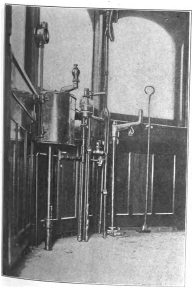
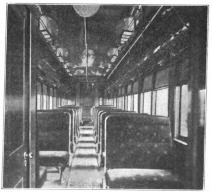
Five cars have been provided with a baggage compartment, and all with smoking compartments. The interior of the cars is finished in mahogany, and the ceilings are painted a light green and gold. All of the cars are provided with a lavatory. In addition to side lights, there are three center clusters supplied with holophane globes which are mounted from the ceilings of the cars. The cars are heated by Peter Smith hot-water heaters. In the combination cars the heating apparatus is located in the bag-gage compartment, while in the straight passenger cars itis located in the motorman's cab.
| |||
| Two-Car Train |
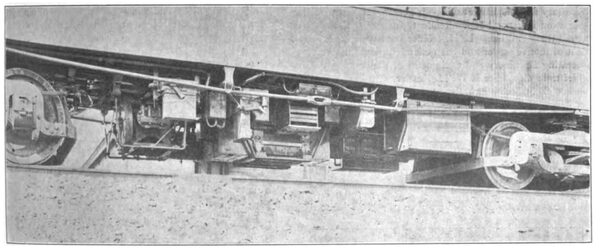
The electrical equipment of each car consists of four100-hp Westinghouse single-phase motors. The gear ratio adopted is 19:64. The Westinghouse unit switch system of multiple control, adapted for operation on both alternating and direct currents, is used. The cars are arranged for double-end operation. The motors are operated two in series with two pairs in parallel on a. c. and all four in series on d. c. There is only one running point on d. c.
| |||
| Typical Waiting Station Used Along Route |
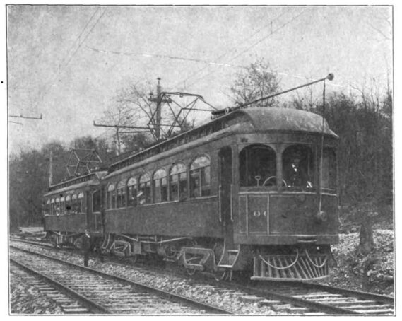
Each car carries two No. 8 U. S. wheel trolleys for use when operating on direct current, and one pantograph trolley for the collection of the single-phase current. Only one pantograph trolley has been pro-vided, as this type of trolley readily lends itself for operation in either direction. The control of the wheel trolleys is taken care of by means of retrievers mounted on the ends of the platforms, as is the usual practice, whereas the pantograph trolley is controlled entirely by air supplied from the air brake system. The control of this trolley is provided for by means of a suitable valve mounted in the motor-man's cab.
| |||
| Standard Car — Pantograph Trolley Raised |
In passing from the direct-current section of the line to the alternating current portion it is only necessary to lower the direct-current trolley and raise the pantograph trolley, and in changing from alternating current to direct current, the reverse operation is to be performed. The only other operation necessary is the throwing of a mall changeover switch controlling the air-pump motor. This can readily be performed without stopping the car or even checking its speed. If it is desired to operate the cars in trains, as is contemplated, this can be accomplished by connecting the cars through the train line receptacles by means of seven-point train line jumpers.
| |||
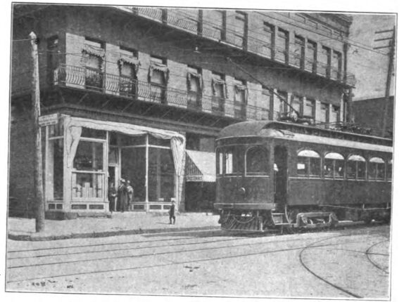
| Butler Terminus and Company's Waiting Room |
Inasmuch as the operating coils for the unit switches receive their current from the main line, means must be provided for testing the motors and operating circuits when the car is not in operation. This is accomplished by the installation of two single-pole, double-throw switches and a testing receptacle, by means of which the motors and control circuits are disconnected from the line and an outside source of power supplied to the car for operating the switches and testing out the circuits.
| |||
| Interior Motorman's Cab |
Especial care has been exercised in the mounting of the apparatus so to distribute it as to equalize the weight on the car body. All car wiring is carefully concealed in loricated conduit, and a sufficient number of junction boxes has been provided at suitable points, which materially cuts down the wiring and facilitates ready access to the connections.
CAR HOUSE AND REPAIR SHOP
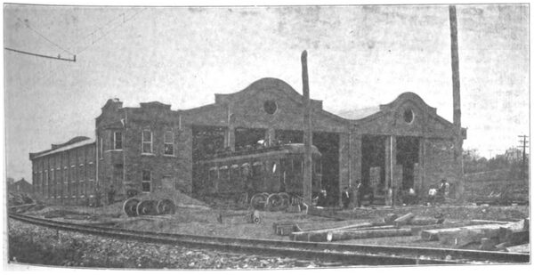
A large brick car house and repair shop is located at Mars, near the center of the system. The building measures approximately 181 ft. x 80 ft. and contains four tracks in the car house section, each provided with a pit, and two such tracks in the repair shop. At the side of this car house, and adjacent to the tracks, there has been built a small brick addition to accommodate the dispatcher's office, and also afford a waiting room for the train crews. The large amount of trackage necessary for such a location has been admirably laid out so that the cars can readily be switched from one track to another with the minimum amount of handling.
OPERATING FEATURES
The general offices of the company are located at Butler, where there is a large waiting room on the ground floor of their office building. This is shown in one of the engravings. At the present time an office is also maintained in Pittsburg, but it is the ultimate intention to direct the entire operation of the road from Butler.
| |||
| Interior of Combination Baggage and Passenger Coach |
The dispatching of the trains is done by means of the positive order system similar to that employed on steam railroads. The movement of all trains is in direct charge of the chief dispatcher, who is located at Mars. When a car is ready to start on its run, the conductor gets in touch with the dispatcher's office by telephone, receiving his orders in the same manner. These orders are then written in triplicate on forms provided for that purpose, and after that they are repeated to the dispatcher to insure their correctness. He gives one copy of the order to the motorman, retaining the other copy; the third copy is retained in the telephone booth for future record.
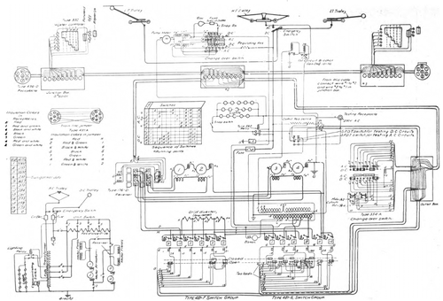 |
| Diagram of Car Connections |
At each siding a small telephone booth has been provided and at these points the train crews receive further orders before moving to the next meeting point.
At the present time the company is conducting only a passenger service, but it is proposed in the near future to equip several baggage cars to handle small freight. In addition to the local cars the company intends inaugurating an ex-press service, which will make single trips in about an hour.
| |||
| View of Under Side of Car, Showing Control Apparatus |
The regular local cars require about an hour and a half for the same run. George Heard is the president of the company, and Charles Gibson, Jr., is vice-president, while H. W. Pape — to whose courtesy the greater portion of the information necessary for this article is due — is general manager. C. L. Wilcoxon is general superintendent, and has entire charge of the track and line. L. H. Kidder is general superintendent of motive power and has general supervision over the operating machinery and equipments of the company. The chief train dispatcher is W. M. Kessler, who has C. O. Fry and A. S. Fullerton as assistants.
| |||
| Car House at Mars |

