[Trade Journal]
Publication: The Journal of Electricity, Power and Gas
San Francisco, CA, United States
vol. 12, no. 9, p. 163-168, col. 1-2
The Pikes Peak Power Transmission.
BY R. M. JONES.
THE Pikes Peak Power Company, the general offices of which are located at Victor, Colorado, was organized in 1899 under the laws of Colorado. During that year it purchased ranch property, placer claims and reservoir sites on West and East Beaver Creeks, in Teller and Fremont Counties, also located, developed and patented placer claims along these streams and at this date owns by patent all of the lands on and along these streams, including reservoir sites and all water power privileges over a distance of one and one half miles on Beaver Creek, seven miles on West Beaver Creek and three and one-half miles on East Beaver Creek, which streams are noted for their excessive difference in altitude in short distances, which enables them to be the means of developing valuable water power properties.
| |||
| Power House, Station A and R. M. Jones Residence on the Left. |
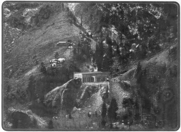
The first of the several power stations which the company contemplates erecting is completed and has been in operation during the past year. This is known as Station A, and is located on West Beaver Creek, in Fremont County two and one-half miles up the stream from the junction of East and West Beaver Creeks. Incidentally, the completion of this station has accomplished much toward the development and actual construction of stations B and C, in the way of reservoir capacity and pipe line delivery of water that is serviceable to the two lower stations after having been used through Station A.
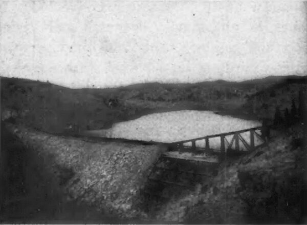
The dam and reservoir for this system is situated five and one-half miles east of Victor, and the former is noteworthy as being the largest steel faced, granite back filled dam ever constructed. The structure is 405 feet in length along the cap, 220 feet long at the base, has a cross section of base of 148 feet and a cross-section of twenty feet of cap. The upper slope, being the steel face, is thirty degrees from the vertical and the lower slope is fifty degrees. The vertical height of the dam from bed rock to top of the sixteenth plate, being the spillway, is seventy feet. The spillway is forty feet wide, is cut in granite formation and passes around the northwest end of the dam. The granite back fill to which the steel plate is laid, is carefully laid in a dry wall of heavy granite boulders, which measure from twenty to eighty cubic feet each as broken from heavy blasting, with loose fine granite filling the intervening space.
| |||
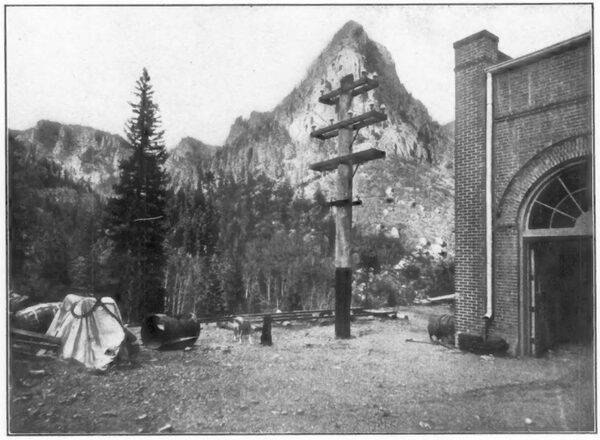
| MasonS Peak and Power House. |
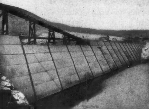
The steel plate is built up of sheets five by fifteen feet in size and laid eight plates in height with one-half inch thickness for the bottom. Continuing, the plate is reduced in thickness to three-eighths of an inch, and finally, at the cap, it is one-quarter of an inch in thickness. The entire sheet is riveted up with horizontal butt straps, and four by five by one-half inch angle bars placed vertically the entire height of the dam across each interval of fifteen feet for the entire length of the dam.
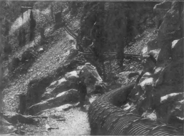
The five-inch leg of each pair of angle bars projects into the reservoir and constitutes a standing joint seam with an iron liner, three-eights by two inches, that is riveted between the extreme outer points of these angle bars, thus making a thorough expansion joint for each section of fifteen feet. The bottom and end connection of the entire sheet is concentrated into a deep channel way quarried out of bed-rock, and the bottom terminates in two pairs of five by eight-inch angle bars, which are riveted through the plates. The end connections are prepared in exactly the same manner, but are applied vertically. The quarrying of the bed-rock channels was carried out horizontally in each case to a point rising to an elevation, and thence the rise was made abruptly in terrace form. The entire sheet is riveted up and calked in the same thorough manner as in boiler practice. A space of six inches was left between the steel plates and smooth sur face of the granite back fill. This narrow space is taken up by sand, gravel and sedimentary deposit, the filling being applied with ample water and permitted to dry before water pressure was allowed to enter the reservoir. The reservoir has a surface area of 130 acres and holds 102,000,000 cubic feet of water. The water is taken into a wood stave pipe through a perforated grizzley 240 feet long, which gives thirty times greater area than the pipe. The stave pipe is 23,200 feet long, is thirty inches in inside diameter and is of one and one-half inch redwood stave banded with one-half inch steel bands and cast iron lugs. The bands are spaced at intervals along the pipe at all distances between two and one-quarter inch and eight inch centers as necessary for resisting the internal pressure, the variations in pressure being caused by various inverted siphons along the line, two of which reach a pressure of 215 feet. This pipe line extends over very rough country, about half of the grade being through original granite formation. Many of its curves were on less than 100 feet radius, and one compound curve was on a radius of thirty-five feet. The wood pipe passes through the Skaguay Tunnel, which has a length of 1535 feet and is located 21,000 feet from the dam. From a point 200 feet below the Skaguay Tunnel, where the static pressure reaches 220 feet, the line consists of steel pipe twenty-nine inches in diameter in various thicknesses of plates, ranging from one-quarter of an inch to three-quarters of an inch, as required to meet the internal pressure with an ample factor of safety.
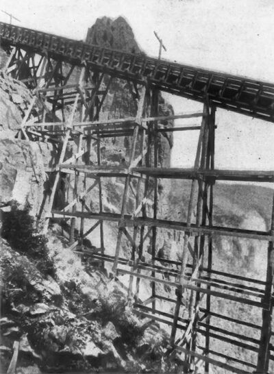
The total length of steel pipe, including the receiver, is 2900 feet, and it is laid on an incline averaging thirty eight per cent. It passes over grades which have been cut through a tougher granite formation in respect to roughness than was ever encountered in railroad construction in Colorado. At one point it passes through an inclined tunnel 335 feet in length, just above which is a bridge seventy feet in height, both being on a forty per cent. gradient, while at various other points there are extremely deep open cuts. From the south end of the Skaguay Tunnel the pipe line is entrenched in the grade on which is constructed a three-foot gage railway leading from the Skaguay Tunnel to the power house, its grade being 1165 feet in the vertical in 3100 feet on the horizontal. The cars of this road, which are the only means of access to the power house, are operated by a double hoisting engine. The upper terminus of the railroad lies under a vertical ledge seventy feet in height, and all machinery, apparatus and materials of all kinds were lowered by boom and derrick, taking. loads from the wagon at the upper landing and lowering them seventy feet over the ledge to the cars, from which point the loads were lowered by friction brake on a hoist equipped with a three-quarter inch steel cable. One thousand four hundred tons of building materials passed down this peculiar railroad.
The power house, known as Station A, has dimensions of thirty-eight by ninety-eight feet, with two side wings measuring sixteen by forty-eight feet each, and is located on the summit of a granite projection surfaced off true to grade. The building is constructed of brick, with arched roof constructed of steel and corrugated steel that is covered with concrete, tar and gravel. Its floor is of concrete and the building is absolutely fireproof. The building is furthermore provided with a ten-ton travelling crane,
| |||
| Thirty-Inch Wood Stave Pipe, 23,000 Feet Long. |
| |||
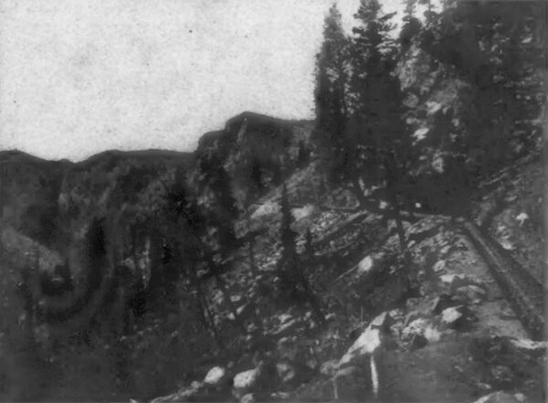
| Wood Stave Pipe, Showing North End of Skaguay Tunnel. |
The hydraulic apparatus was manufactured by the Pelton Water Wheel Company, of San Francisco. Each unit consists of two steel disk wheels sixty-six inches in diameter, keyed to the same shaft and working in the same wheel house. The base frames are built up in a box pattern of the same type and general design as that of the generators to which they are connected. The frames of the water wheels and generators are faced for accurate, rigid connection to each other by bolts and dowels. The connection of water wheel and generator shafts is effected by a 7000 pound steel cast balance wheel banded with a rolled tire steel band that is four inches in thickness. The wheel is seven feet in diameter, and its hub forms the connection on the water wheel shaft, and one-half of the hub forms the other half of face coupling and is keyed to the armature shaft, forming an accurate and rigid connection of the shafts of the two machines.
The nozzles used with which to produce the required power, as applied under the effective head of 1160 feet which is obtained, require only a diameter of one inch to produce energy of 236 horsepower, including losses. The nozzles for each unit vary in diameter, one nozzle having the capacity of the generator and the corresponding nozzles for the other wheel in the same unit being somewhat reduced. Each wheel in each unit will produce power for the full capacity of the generator connected. In operation, however, it is customary to install such varied diameter or capacity of nozzles as to permit the operation of the full capacity of the load demanded from time to time by the operation of nozzles under full pressure, entailing but slight loss in water due to regulation for low loads.
| |||
| Dam During Construction. |
| |||
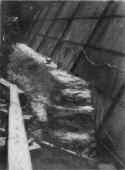
| Steel Face of Dam Showing Concrete Connection With Bed-Rock. |
| |||
| Steel Face of Dam During Construction. |
The nozzles are of the deflecting type, and work under full pressure at all times, which-is the cause of such variation in the diameters of the nozzles. The regulation is of the manual or Armstrong type, owing to the fact that without reference to the class applied automatic regulation under existing conditions could only be a failure. Due provision has been taken to extend the actual control and regulation of each unit to a point directly in front of the switchboard panel belonging to that unit. The receiver runs longitudinally through the building under the steel-concrete floor. The discharge, or tail-race, water returns directly under the receiver to the south or lower end of the building, at which point it will later unite with water conducted from a point 800 feet above Station A, where a catcher dam is to be constructed, and the water diverted from the Beaver Creek channel. There being a considerable accumulation of water between the dam and Station A, it is the purpose of the company to unite the waters from Station A with this accumulation in the stream and conduct the combined waters through a pipe line to a point 200 feet above the forks of the East and West Beaver Creek, at which point there will be constructed Station B. There will be built a small pipe line up the East Beaver to the same static level as the tail-race water of Station A. The waters of both pipe lines will be united before entering the receiver. The pressure of Station B will be 1257 feet or 544 pounds pressure per square inch. With the added accumulation of water in the West Beaver branch, 3500 horsepower will be obtained, and from the East Beaver branch about 2000 horsepower, all of which may be developed at Station B.
The electrical generators now in operation at Station A are four 400 kilowatt General Electric machines, three phase, thirty cycles, 600 volts, with stationary armatures and rotary fields, making 450 revolutions per minute. As already mentioned, the generators are driven by direct connection to the water wheels. Two four-pole direct current machines, exciters having a capacity of thirty kilowatts each, run at 675 revolutions per minute, and produce an exciting current at seventy volts, each gives sufficient exciting current for all four generators while working at full load.
In reference to the efficiency of the water wheels, it may be stated that they were guaranteed to develop eighty-three per cent. of power on their shafts at full load under conditions when the nozzles are in normal position. In considering the efficiency of the water wheels, the generators were assumed to have a commercial efficiency of ninety-four per cent. at full non-inductive load, therefore with every 33,000 foot-pounds of water the water wheels will produce in current one indicated horsepower, less seventeen per cent. loss in the wheels, and six per cent. loss in the generators, delivering 78-100 horsepower, or 582 watts, from the brush holder terminals of the genera tors. These efficiencies have been fulfilled by tests. All water connections are tested to 800 pounds pressure to the square inch. In making the efficiency tests, measurements are made through the standard weir commonly used in the United States, which measurements are verified by spouting tests in working water through nozzles of known diameters. The developed power is measured by the highest grade electrical instruments obtainable.
| |||
| Steel Pipe and Railway Bridge on Forty Per Cent. Gradient. |
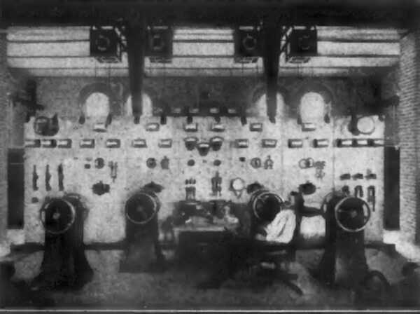
The switchboard apparatus is especially liberal in design, and is made up of one exciting current panel, four generator panels, two distributing panels, two high tension panels and one paralleling or synchronizing panel. Each panel is made of Vermont marble, sixty-two by thirty-six inches, with a sub-base twenty-eight by thirty-six inches, and two inches in thick ness, with a complete equipment of indicating and recording instruments, switches and regulating apparatus. The main line switches from each machine are operated independently either for power or light. The circuits are arranged so that any or all of the machines may be applied on either circuit. The transformers are six 250 kilowatt air blast type of the General Electric make, having 600 volts on the primaries and 12,600 on the secondaries. The twelve complete sets of lightning arresters are also of the General Electric make. The cable connections between the generators and switchboard and from the switchboard to the transformers are all highly insulated, paper, rubber, lead and laid in conduits in the concrete floor. Since the early operation of this station, it was found necessary to install some thorough system for combined are and incandescent lighting, which has b2en fully accomplished by the installation of two 200 kilowatt compensated type three-phase generators, sixty cycles, with their full equipment. These generators are of twelve poles, and operate at 600 revolutions per minute. Each generator contains its own independent direct current exciter of twelve poles, built directly on the revolving field shaft. These machines are also directly connected to Pelton type water wheels. Finally, it may be said that as to apparatus, building general arrangements, quality of construction and general finish, this generating station cannot be surpassed in any other like station in America. The line transmission from Station A to the center of distribution, which is in the Gold Coin Mine at Victor, includes a distance of eight miles by pole line. The power circuits consist of three wires of No. 4 B. &S. gage, and the lighting circuits of three No.6 B. & S. gage wires, which are ample to deliver 1600 kilowatts at less than a five per cent. energy loss. These lines are transposed at intervals of each one-half mile along the line. The poles also carry for telephone purposes two No. 10 galvanized iron weatherproof wires, transposed each 120 feet. The insulators were furnished by R. Thomas & Sons Company, of East Liverpool, Ohio. They are of porcelain, five and one-half inches in diameter, and each is made up of three independent cups. In manufacture they are subjected to a 40,000 volt salt test. The line voltage is 12,600, both on the thirty and sixty cycle lines.
The substation which is a brick, steel and concrete structure, and is therefore fireproof, adjoins the Gold Coin ore house, in Victor. All transmission circuits enter this building where the current is transformed through nine fifty kilowatt General Electric oil transformers, having potentials of 12,000 volts in the primary and 115 and 460 volts in the secondary, the secondary being connected in the Y four-wire system, for permitting local lighting distribution and local power work. There is also a set of three fifty-kilowatt oil trans formers, 12,000 to 350 volts, which operates a 120 kilowatt rotary converter, which in turn operates a locomotive in the United Mines transportation tunnel for ore hauling from first level of the Gold Coin Mine to the Economic Mill, as well as for Bull Hill tunnel haulage. The high pressure distributing lines leave the substation in various directions, after first passing through 20,000 volt oil switches, making each line independent, to the Economic Mill, where about 300 horsepower is delivered; to the Beacon Hill power distribution for hoists, power and lights; to the Deadwood Mine, where a 100 horsepower air compressor is operated. Furthermore, the secondary 460 volt power circuit reaches Independence, Altman and the Wild Horse districts. Another primary line reaches Cameron and Gillett, after first passing through Gold field, all for lighting services, and distributed in each of these towns through local transformers connected in delta.
Two additional primary distributing lines reach Anaconda, where independent lighting and power is distributed to the town of Anaconda and the various mines in that vicinity, notably the Morning Glory and Doctor Jack Pot mines. These lines also reach Elkton on its way to Anaconda, where lighting is also distributed. The Pikes Peak Power Company has just begun, in fact, to reach its various points of distribution. It has reached all the places and properties mentioned with a good series alternating system of sixty cycles are lighting, which is distributed in three directions through one seventy and one fifty light constant current transformer located in the Victor substation.
| |||
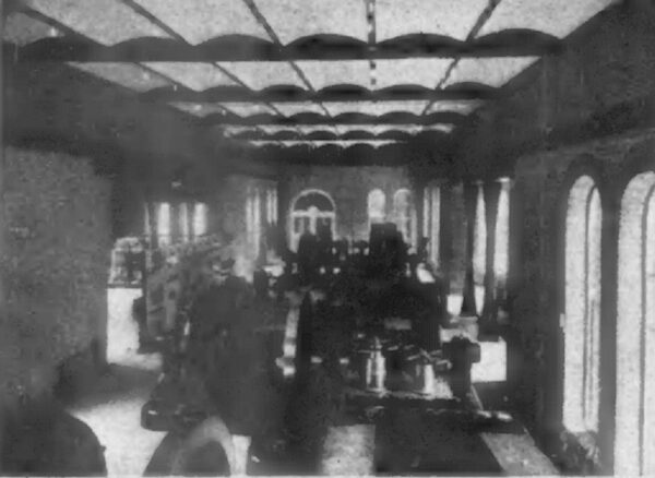
| Interior Station A. |
| |||
| Switchboard, Station A. |
| |||
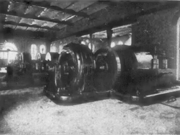
| Interior Station A Before Completion. |
It is the purpose of this company to construct an in dependent transmission line from Station B to Station A, and possibly an independent line to the distributing stations in Victor, including the connections through Station A, thus permitting the entire energy of the stations to work in parallel over either stations lines or to work each station independently as desired. It is also proposed that transmission lines will be extended from these stations to other localities within reach. Thus, with two complete pipe lines, pole lines and generating station systems, the most unquestioned reliability may be counted upon. The distribution of light and power, together with the companys independent telephone system, constitutes one of the most valuable systems of its kind in the country.
It is also the intention of the company to install a third station on the combined Beaver streams at a point near the mouth of the canyon, and approximately two miles below Station B, the lower one to be known as Station C. Here the difference in elevation is but 373 feet, but the volume of water it is believed will reach fifty second-feet, which could develop 2100 horsepower, less losses. The company also owns an excellent reservoir site on East Beaver Creek at an elevation of 1700 feet above Station B and but two and one-half miles distant, which reservoir may be developed to excellent advantage in the near future.
As to financial considerations, it may be stated that the Pikes Peak Power Company has a stock issue of $1,000,000 and an authorized bond issue of $150,000, all of which is owned by the Woods Investment Company, of Victor and Colorado Springs. The present cash value of the power company alone is over $1,000,000. The power company is represented by Warren Woods, president; H. E. Woods, vice-president; F. M. Woods, secretary and general manager, and R. M. Jones, engineer and general superintendent.
The company was organized and the property developed originally by the Woods Investment Company for the purpose of supplying power and light to the milling and mining interests owned and controlled by them in the Cripple Creek mining district, but the work of construction was carried out to much larger magnitude than at first intended, therefore the company is now supplying current to other properties and doing a large proportion of the lighting in the various towns in the district.
The engineering in every department of the construction, from the beginning to the present operation, was carried out by R. M. Jones, who will be remembered by many as the engineer of the Big Cottonwood Power Company and the Jordan Narrows plant, both in the Salt Lake Valley, Utah, and prior to this in the construction of central lighting plants and street railways in Wyoming, Montana, Utah and Nevada, beginning with the Laramie Edison plant in 1886.
