[Trade Journal]
Publication: The Journal of Electricity, Power and Gas
San Francisco, CA, United States
vol. 12, no. 10, p. 185-188, col. 1-2
The Swan Falls-Trade Dollar Transmission.
BY E. J. KOPPITZ.
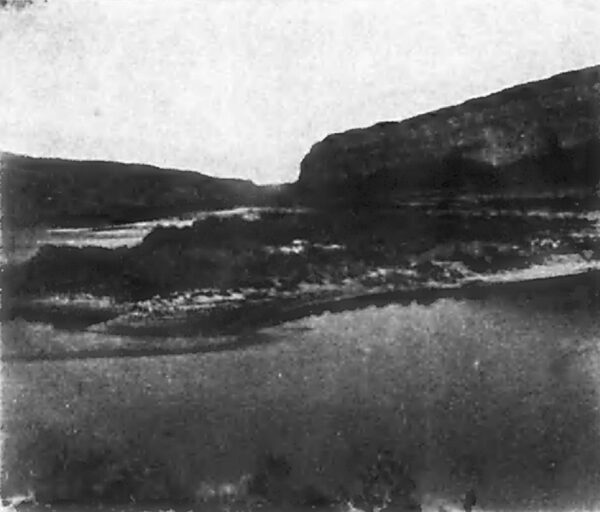
MIDWAY between Boise and Silver City, Idaho, running in a northwesterly direction, Snake River, the main tributary to the Columbia, the headwaters of which have their origin in the famous Yellowstone Park reservation, in Wyoming, winds its way down a steep and narrow canyon, in some places having cut its way through a lava formation a distance of 800 feet below the surrounding country, which in this vicinity is dotted here and there with sage brush, giving one the impression, although on a much smaller scale, of the Grand Canyon of the Colorado.
|
The adjacent country on both sides of the river being void of timber for fuel purposes, and also the great distance of their location from any railroad, made the operation of the Trade Dollar Mines rather expensive. Steam coal costs $15.09 a ton delivered, and as about 3000 tons was used per year, the fuel bill amounted to about $50,000 annually. It was therefore decided to install an electrical transmission plant on Snake River. After some preliminary surveys on different parts of the river, it was decided to locate the plant at a place called Swan Falls, where the river had a natural fall of about ten feet. This point was further decided upon because of the existance of an island in the center of the stream, which divided the river and could be utilized as part of the dam. The land on the east side of the river was owned by Messrs. White and Cressy, two placer miners who were experimenting with a new gold saving device which Mr. White had brought out from the East. The gold at this particular place being too fine to be saved even by their process, they disposed of their holding to the Trade Dollar Company for a nominal sum.
In April, 1900, work was commenced with a large force of men. Interest in the enterprise never flagged, and in eleven months from the time the first pick was stuck into the ground, power was being sent over the line to Silver City.
The first thing to be done was to build a suitable roadway from the top of the canyon to the bottom. About two miles further up the river was a natural sloping valley which came to the water's edge, but it was impracticable to build the road through it, because if it were done, as soon as the dam would be completed the part of the road around the cliffs would be submerged, so the route finally determined upon started at the power house site and by a few turns and some heavy grades wound its way up the steep sides of the canyon. Considerable blasting was necessary to remove some of the rock. In the meantime supplies were brought down through the little valley, better known as The Red Trail, and so named, perhaps, because of the many Indian massacres that occurred in this valley, which being one of the few places convenient to water, was often used by early settlers as a camping place. While still at work upon the road, work progressed on the coffer-dam that was built from the island to the east bank of the river for the purpose of turning the whole stream through the west passage. A donkey engine and centrifugal pump were used to drain the coffer-dam of seepage water while clearing the bedrock and laying the foundation for the concrete dam and power house.
| |||
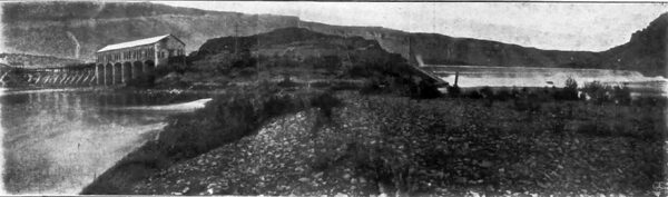
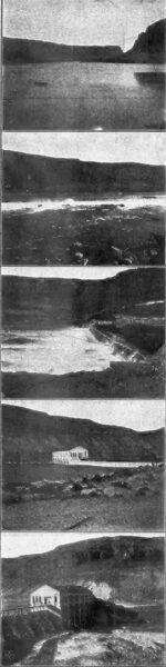
| The Dam. |
| |||
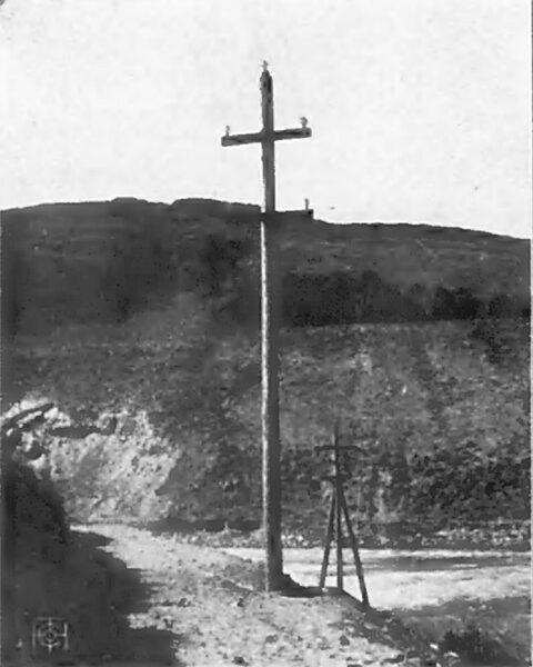
| The Pole Line. |
| |||
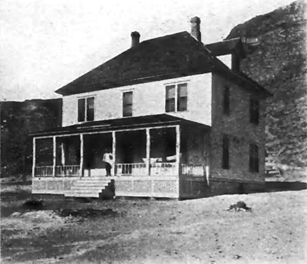
| The Cottage. |
The power house is a substantial building of concrete with a slate roof. It forms part of the dam, and was built of concrete blocks which were numbered and made to form. The building is forty-four feet by 140 feet in area and runs lengthwise across the stream. Six wheel pits were built, although but four are being used at present. The section of the dam which connects the power house to the island is in reality but a continuation of the main dam, although this section is short, being only some thirty odd feet in length. The main dam is over 300 feet long, is slightly V-shaped, and is built in line with the building for one-half the distance, the remainder heading for a point of rock which extends out from the shore a little distance, thereby shortening and strengthening the dam. The dam across the west passage was the most difficult part of the whole undertaking. As will be seen in the accompanying illustrations a concrete bulkhead was built in two sections, one being next to the island and the other on the west bank. Across these a crib dam was built, its total length being 425 feet. The main channel of the river was close to the bank, which made it any easy matter to put in a coffer-dam, so that the island end of the crib work was comparatively easy to construct. But damming the main channel was a game two could playnature versus engineering skill. All but about sixty feet of the main channel was closed without much difficulty, but after that the trouble began. Across the open gap the frame-work of a crib was run and huge piles were driven down, only to be washed out. Nothing seemed to be able to withstand the terrific force of the water. After several vain attempts to use piling, two cribs were built, measuring thirty feet by twelve feet by twelve feet, of twelve inch by twelve inch timber, and placed in a position one on each side of the opening. These cribs were filled with rock and sunk, the space behind them being also filled in until it was solid with the crib-work. When this was accomplished a smaller crib was made and placed in between the two larger ones, when it was also sunk, but it went through the opening with a terrible crash, turning end over end, and breaking up like a house of jack-straws.
After this failure it was next decided to build a larger crib on the east bank, its dimensions to be sixty feet by thirty feet by twenty feet, and of twelve-inch timbers, bolted together with twenty-foot bolts. Captain Clark of Pittsburg was sent out to superintend the placing of this new crib in position across the gap. Before its completion it was floated into deep water and there finished. The task of taking it up stream was not so difficult as it was tedious. When up stream far enough it was swung across and allowed to float down at the same time, being guided from both sides by heavy ropes. As it neared its destination its velocity increased to such an extent that the strain on the guy ropes caused one of them to break, letting the crib go endwise instead of crosswise. Nevertheless it remained in position after being sunk. Small triangular shaped cribs were next made and placed around the larger one. The whole thing was then filled in with rock and gravel, and today it is claimed that there is not a more substantial crib dam in the entire western country.
|
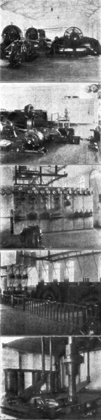
The contracts for the hydraulic machinery were given to the S. Morgan Smith Company, of York, Pa., which furnished four seventy-two-inch vertical McCormick turbines, to operate under a head of seventeen and one-half feet, with a speed of seventy-eight revolutions per minute. The arrangement of the wheels, line shafting, pulleys and generators can best be explained by reference to the illustrations on this page. There are six jaw clutches on the main shaft, dividing it into seven sections, four of which are taken up by wheels and three by driving pulleys, thereby enabling any combination to be made. The governor here used is a Type B Lombard. A seven and one-half horsepower Type C induction motor drives the governor pump, while a three and one-half horsepower motor drives the governor end of it. The gearing is so arranged that either one or all the wheels can be connected. The screen in front of the wheels consists of flat iron bars, three-eighths of an inch by two inches, set one inch apart, in a vertical position.
The generators, as well as the rest of the electrical equipment, was furnished by the Westinghouse Electric and Manufacturing Company. The generators are three in number, each being of the 300-kilowatt, 500- volt, sixty-cycle, two-phase, three-bearing type, running at a speed of 514 revolutions per minute. The pulleys on the machines are wide enough ; to accommodate a forty-four inch belt. Two fifteen-kilowatt, 125-volt, multipolar machines furnish the exciting current. They are belted from the main shaft next to Nos. 1 and 3 generators. No. 2 generator may be run in parallel with either No. 1 or No. 3.
The switchboard is of white marble and contains seven panels, made up as follows: Panel No. 1 is the exciter panel, and contains two voltmeters, two ammeters, two rheostats, and two triple pole single throw switches besides the voltmeter plugs. Nos. 2, 3 and 4 are machine panels, and each contain two alternating current ammeters, one direct current ammeter, field rheostat, and a four pole single throw switch, besides voltmeter plug, ground detector switch and lamp, and synchronizing device. Panel No. 5 is the load panel, and contains two alternating current ammeters, a kilo watt meter, and a recording wattmeter. Panels 6 and 7 are feeders, and each contain two alternating current ammeters and two double pole single throw switches. Two voltmeters on a swing-arm bracket are on the left hand side of the board.
|
Current is conducted through lead covered cables from each machine, which pass through the concrete floor through glazed clay bushings. Insulator racks under the floor carry the cables to the switchboard. From the feeder panels the cables pass through the floor and come up behind their respective transformers.
The raising transformers are five in number, one being held in reserve. They are of 160 kilowatts each, and are of the air-cooled and oil-insulated type, stepping the voltage up from 500 to 22,000 volts. They are connected two-phase on the low tension side and three-phase on the high tension.
The high tension switches used are of the broomstick type, and connect each high tension lead to the high tension busbars. They answer every purpose for which they are intended. A time limit circuit breaker is used, and behind this are three static interrupters and three 22,000-volt low equivalent lightning arresters.
The lighting of the building is done by three Adams Bagnall enclosed arc lamps, run from the 125-volt exciters. The incandescent lamps, supplied from a transformer, are placed along every beam, so that the chances of being left in the darkness are reduced to a minimum.
The insulation through which the line passes as it leaves the building is a hard rubber tube, four feet long, enclosed in a seasoned piece of timber measuring six inches by six inches, and three and one-half feet in length, which in turn passes through a piece of marble thirty inches square and one and one-half inches thick. The pole line is thirty-two miles in length and leaves the island in a single span of 600 feet to the west bank. Round cedar poles, with an average length of thirty-five feet, are used throughout, and the line is of No. 4 hard drawn copper, the wires being placed four feet four inches apart, forming an equilateral triangle. Forty thousand volt insulators, made by the Hemingray Glass Company, of Kentucky, are used, and give splendid satisfaction. The main line is transposed but twice, while the telephone line is transposed every other pole. It is a very quiet line.
Power is distributed to various places on the companys property, where circuit breakers, static interrupters and lightning arresters are used at each step-down station. Lightning is a thing to be guarded against, as Silver City is 8000 feet above sea level. The motors used range in size from two to 100 horsepower, and in entirely supplanting steam they are performing each and every duty requiring power in mining service.
A substantial hard finished two-story house, with all the modern conveniences, was erected by the company at the falls for the use of the operators. A number of trees and a garden were set out, which turned a barren waste into a very comfortable abode, about which the barns, blacksmith shop and oil houses gives the place the air of quite an enterprising community. In fact, the extreme consideration which the company gives to insure the com fort and welfare of its employees is conceded by it to constitute one of its wisest investments.
Of this company the Hon. James Hutchison is general manager. Mr. Willard White was superintendent during construction and Thomas F. Johnson was consulting engineer. To A. J. Wiley, the mechanical and hydraulic engineer, is due the credit of the supervision of the installation of the undertaking, while Mr. James Johnson, of the Mountain Electric Company, of Denver, Colo., was the electrical engineer for the Westinghouse company.
And this utilization of a few of the innumerable water falls to be found in the United States for the transmission of electricity to run the machinery of all kinds of enterprises, is only the beginning of a system that is destined in the not far distant future to revolutionize the motive power of the world, for this is a system whose marvelous potency will soon be felt wherever the sun light of civilization extends.
