[Trade Journal]
Publication: Electrical World and Engineer
New York, NY, United States
vol. 40, no. 18, p. 691-694, col. 1-2
20,000-Volt Three-Phase Plant in France.
BY P. LETHEULE.
HIGH-VOLTAGE transmissions are rare in France and though many projects have been proposed, they will probably await the commercial success of the plant forming the subject of this article. This plant is situated in the Department of Aude, in the extreme southeast of France, of which Carcassonne and Narbonne are the principal cities. The generating station is situated in the Corbieres, at the mouth of Saint Georges, near Quillan. The total head of water is about 330 feet. The dam is in the river Aude, about 35 miles from its source in the mountains.
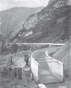
The dam at Saint Georges is a solid masonry structure. A canal having a total length of 18,000 feet extends underground for some 13,000 feet, and is open for the remaining 5,000 feet. The open portion is built of cement supported by wood in a very similar manner to the construction used for the Simplon tunnel generating station. The size of the underground part of the conduit is 6 1/2 x 6 1/2 feet. The incline is 7 feet per mile. In the open part of the canal this incline is increased to 10 feet, and the section reduced proportionately.
The canal brings water to a forebay from which lead two iron conduits of 3 feet 3 inches diameter to the generating station. These conduits are supported every 10 feet of their length by masonry, on which they can slide, and an expansion joint is provided every 650 feet. In a length of 650 feet the loss of head is 3 1/2 feet.
| |||
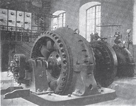
| Fig. 1. Interior of Generating Station. |
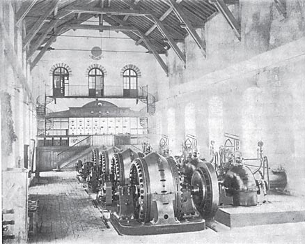
The generating station is built over the iron conduits bringing the water to the turbines, and consists of a rectangular building of one floor, sufficient for eight groups of machinery, of which four are now installed and in service. At the end of the building is erected a platform, supporting the low-tension and transformer panels. In an extension of the building at the back is erected a high-tension switchboard and transformer room.
The generators deliver three-phase alternating current, at 2,900 volts, 50 cycles, to the low-tension panels in the generating room, and thence to the secondary low-tension side of the step-up transformers, the high-tension side of which delivers 20,000 volts.
The turbines are rated at 800 hp at 300 r. p. m. The wheels are of the Pelton type and were built by the Ateliers de Construction de Vevey. They are regulated either by hand or by an automatic regulator of the mechanical type. The distributor to the turbine offers four openings, which can be more or less regulated by a cylindrical valve controlled either by hand or by an automatic hydraulic regulator. The hydraulic regulator uses water under pressure from the conduits, which is previously cleaned by being passed through a filter. This regulator works perfectly, a sudden difference in load of 50 per cent., not affecting the speed above 4 per cent., and 100 per cent, variation, affecting the speed less than 10 per cent. It might be feared that the sudden difference in pressure would be dangerous to the conduits or the connections, but a regulator has been installed for preventing such a disastrous effect; it simply opens an outlet valve and discharges the water in case the pressure gets too high. The conduits conducting the water under pressure are also protected by tubes connecting with the open air at some distance above the station.
 |
| Fig. 2. Map of Transmission System. |
The efficiency of the turbines reaches 77 per cent, at full load. Their axis is feet above the level of the water on the lower side, but the corresponding power is not entirely lost, an exhaust tube being designed for admitting air and water, giving a kind of relative vacuum, and allowing a certain amount of the power to be regained.
The generators are Alioth three-phase machines. Their rating is 700 kw for a power factor of 100 per cent, or 540 kw for an 80 per cent, power factor. They operate at 50 cycles and 300 r. p. m., and generate 2,900 volts. The revolving part is entirely of iron with no windings. The fixed windings are star connected. The exciter is run on the end of the shaft, as in most German and Swiss installations. The exciting voltage is 50 to 60 volts, and the exciting current 25 amperes for full load, which gives .25 per cent, excitation loss. The efficiency at full load is 93 per cent. The drop in voltage is 5 per cent, for non-inductive load, and 16 per cent, for inductive load, 80 per cent, power factor. The weight of each machine is 35 tons, 12 tons of which are accounted for by the revolving part.
 |
| Fig. 3. Diagram of Connectiions of High and Low-Tension Lines. |
The cables from the machine to the low-tension switchboard in the gallery are provided with silver fuses. These cables are supported on porcelain insulators, and are provided with highly insulated connections.
The connections of the generating panels allow the machine to be run in parallel on one set of bus-bars, to which the low-tension secondaries of the step-up transformers can be connected. The voltage regulation of the alternators running in parallel is by hand, the field rheostats being mechanically coupled together and controlled by one single handle.
The high-tension step-up transformers which are between the high and low-tension switchboards consist of single-phase transformers, star-connected in the way well known in the United States, but which is quite exceptional with continental constructors. In spite of the high voltage, the transformers are not cooled with water or oil; the windings are simply exposed to the air, though it is proposed to employ mechanical air ventilation if necessary.
The high-tension side of the transformers is controlled by switches placed on the high tension switchboard, above the transformer room. The peculiar feature of these is the pneumatic or compressed air control from a distance, enabling the circuit to be opened or closed from the generating room by a man at the low-tension switchboard. There is a compressed air reservoir giving 90 lbs. pressure per square inch, which compressor is run by a low voltage, three-phase induction motor.
Reference to the accompanying map will show the extent of distributing network, which seems at first sight disproportionate to the amount of power distributed, which is only some 1,600 kw, though intended in the near future to reach a total of 3,600 kw. This is far from being a great amount of power, but France is not a country possessed of great sources of hydraulic power as are the United States and a few countries in Europe, such as Switzerland, Sweden or even Italy and Germany. The total length of lines reaches 240 miles, and will be extended to 360 miles. The distance from generating station to distributing center is 42 miles, and the main high-tension feeders distributing power from this center to the main transformer stations are from 18 to 24 miles long, so that the total distance from the central station to distributing points attains about 80 miles.
| |||
| Fig. 4. Armored Cement Water Conduit. |
Three-phase transmission was selected, the choice being due to the power being required for public and private lighting and for small and large motors in many branches of industry. The long distance and . the unusually large numbers of centers of distribution led to the adoption of alternating current, due to its great facility of transformation to various voltages. The presence of motors on the network of lines led to the use of polyphase current, the simplest and best form of which was deemed to be three-phase. The use of current for lighting led to the adoption of a frequency of 50 cycles.
All the hydraulic plant was designed and built for an output of 3,600 kw, but as only half this power was contemplated at first, the electrical plant is laid down for the latter output, further units to be added as required. Although this output is not very considerable, the tension of the line is quite high, 20,000 volts having been chosen. This pressure is not too high, as will be seen from the calculations given further, the diameter of the copper wire being 7.5 mm. The promoters, however, considered it advisable that the pressure should not be increased beyond 20,000 volts, by reason of the large number of small transformers and motors utilizing the power along the whole extent of the line, and also of the greater expense and difficulty of maintenance and inspection. A few special transformers have lately been installed, at the request of customers, for a power output as low as 3,500 watts, the construction of which for 20,000 volts entails special care and high cost. The low-tension winding is placed directly on the core and inside a porcelain sleeve with large projecting ribs, around which the 20,000-volt primary is wound.
| |||
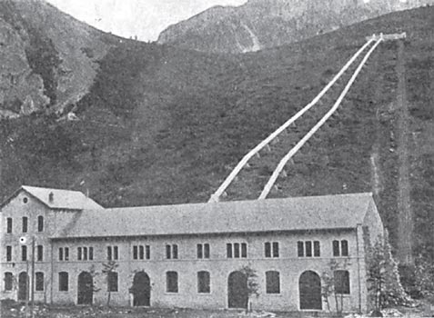
| Fig. 5. Power House and Draft Tubes. |
High tension is not used for the whole of the distributing lines running to the numerous small towns and villages where light and power is distributed. The voltage used here is 150 to 300 volts; an intermediate voltage of 5,000 is also used, stepping down to 125 volts for local distribution.
The 5,000-volt distribution has no special interest, but the 20,000volt transmission line deserves more than passing notice.
The 20,000-volt transmission line of 80 miles is divided into sections. The first 42 miles of line running from the generating station to the main distributing center has been calculated for a loss of 20 per cent, in the transmission of 1,620-kw inductive load at 80 per cent, power factor. The resistance is determined from the following formula:
 |
R being the resistance of the cable, and I the current. The current amounts to 54 amperes, and thus the resistance of one conductor is 36.06 ohms; allowing for impurity of copper and a temperature of 15° C, the section adopted was 38 mm2; that is, a diameter of 7.5 millimeters for the conductor.
The drop in volts due to resistance is represented by the formula,
 |
to be 3,240 volts, and the volts at the generating station 20,240. It follows from the above that the weight of the copper reaches 75 tons, in spite of the high percentage of loss in the feeder.
The voltage at the central distributing point is in consequence regulated between 17,000 and 17,200 volts, according to indications received at the generating station from the receiving or distributing point. The stations are connected by telephone, and it has become quite feasible through experience acquired to regulate the voltage at the generating station by watching the total-output ammeter.
As to impedance, the distance between wires being 2 feet, we arrive by Blondel's formula, subtracting the mutual inductance from self-inductance of the two wires, at a value of inductance of 1.7 milli-henrys per mile; so that the resistance factor, which is the ratio of reactance to ohmic resistance, is about 0.641 for the frequency of 30 cycles. This inductance increases the drop in volts by
 |
p representating the relative loss of tension and m the reactance factor. Three per cent. has, therefore, to be added to the voltage of the generating station, to compensate for this impedance drop.
The effect of capacity can be approximated by assuming a condenser placed at a certain point in the line, the charging current of which will be about 4.6 amperes at 20,000 volts. Experience does not check these figures, as the ammeter shows 10.2 amperes as charging current with a tension of 17,600 volts at the generating station at no load. This changing current is equivalent to about 300 apparent kw-amperes; that is, half the rating of one generator. The current, however, leads so much that it is sufficient to allow 6 amperes exciting current to obtain the normal voltage at the terminals of the machine, instead of 12 amperes required when running. Experience has verified that the charging current is proportional to the pressure and to the frequency. It has been remarked also that the generating station voltage being 17,600 volts for no-load on the line, the rise due to capacity reaching 700 volts, the voltage at the end of the 42-mile feeder amounts to 18,300 volts.
There are three branch lines running from the main distributing center to the three main distributing stations; by adding one of these lines to the length of the main feeder, thereby increasing the length from 42 to 60 miles, we decrease the charging current from 72 to 38 amperes. By including another 25-mile branch line from the distributing point, no modification of this figure is obtained.
The following table gives the value of charge current obtained when the line was tapped at different successive points along its length, as mentioned on the top of the columns:
 |
These results can be deduced from theoretical calculations though the exact laws of distributed capacity are rather complex. Moreover, the capacity has proved to be of no importance under load, and even with the sudden interruption, due to the blowing of a fuse, the rise in tension has never been dangerous. The maximum observed has been 32,000 volts. No resonance effects have been experienced, in spite of the presence of a third harmonic of a very considerable relative value in the curve of the alternators.
| |||
| Fig. 6. Alternators at Generating Station. |
The feeder is made of three cables of 38 mm.**2 [mm. squared], separated at a distance of 2 feet. They are supported by wooden poles, 32 feet high, placed 130 feet apart. The poles were treated by soaking them in kerosene. The insulators are of French design, and are provided with triple petticoats, as shown in Fig. 7. The insulators used have been tested to 40,000 volts. The defective insulators could easily be detected at night, owing to certain luminous effects which were never shown by good insulators.
The insulators have worked satisfactorily, and only a few defective insulators have had to be replaced. They have been covered with snow which reached to the tops of the poles, but no accident has arisen. Galvanometer readings showed an insulation of 500,000 volts between the three conductors and the ground. Rainy or overcast weather reduces this to 100,000 volts.
A telephone line is supported by the same poles, 7 feet below the power line. The telephone lines are crossed every 10 poles, so as to compensate for effects of inductance. The working of the telephone is satisfactory as long as the insulation of the line is good, the inductive effects being negligible.
 |
| Fig. 7. Line Insulator |
The chief engineer of the line supervises the line and has three assistants under his charge. The first 42 miles of the line is inspected by seven men, under the supervision of the chief of the line, and the branch lines of 20,000 volts are similarly inspected. Short circuits have been occasioned by trees and by various birds. In case of a short circuit, the tension rises as high as 35,000 volts, but the lightning arresters always protect the line in these cases.
Though the low-tension lines present no special interest, the transformer stations are worthy of notice. The main transformer station is situated in the center of distribution, Fabrezan, from which all tensions are regulated. All transformer stations stepping down from 20,000 to 5,000 volts are protected at the entrance of the line by lightning arresters of the "horn" type, with resistance and inductive coils.
The switchboard is entirely made of iron, and only the low-tension panels at the generating station are composed in any part of marble. The instruments, ammeters, voltmeters, etc., are insulated from the iron switchboard by means of porcelain insulators. The connections are all made of copper, non-insulated, and supported by insulators identical to those used on the line.
The three branch lines running from the central distributing point gives rise to a supplementary loss of power of about 5 per cent. They feed a certain number of distributing points along their course, and are mostly designed for feeding three terminal points at which the tension is stepped-down from 17,000 to 5,500 volts, fed into the secondary network. These distributing points use transformers of 100 kw, protected by lightning arresters of the "horn" type.
The up-keep of the secondary network is much less difficult than that of the primary lines. A great number of secondary posts are distributed on the system, stepping-down the voltage from 5,000 to 125 volts, for supplying motors and lamps.
Motors constitute about half the load of the station. Most of these are small induction motors, wound for 250 volts, with self-contained resistances. They are started by means of the resistances, which are cut out by a bronze contact operated by means of a rod inside the shaft of the motor. Some induction motors, however, have to be started under considerable load, and their starting resistances attain large dimensions; they, therefore, constitute a separate part distinct from the motor, and their final short-circuiting is by means of carbon brushes with rings mounted on the motor shaft.
Some of the motors, it is to be remarked, have an arrangement for automatically bringing into circuit the starting resistance of the induction motors in case of sudden interruption, and thus avoiding the restarting of these motors without resistance.
Only two synchronous motors have up to now been in operation, one at Carcassonne and another at Narbonne, for distributing direct current to the old Edison systems of these cities. These motors, which are rated at 150 kw each, are direct-coupled to dynamos running at 430 r.p.m. The motors are wound for 500 volts, and are fed from the secondaries of transformers of 200 kw each.
The motors are started from the direct-current side, and it has been observed that the synchronization of the first group causes a rise of voltage as high as 25,000 volts, with no load on the line. When the motor is put on the line previously loaded, no difference in voltage can be observed.
In case of short-circuits on the line, the motors sometimes drop out of step, and the switchboard attendant then generally lightens the load by decreasing the excitation of the continuous-current generators. It often happens that when the short-circuit ceases, the motor can be loaded again, thus avoiding the dropping out of step of the group. Synchronous motors are used in these two stations, because it was intended to employ them to regulate by raising the voltage of the line by over-excitation, but up to the present this has not been done.
The price for current has not yet been rendered definite. Municipal lighting is granted free of charge to the Communes in exchange for certain rights secured by the company. Every 1.000 inhabitants are entitled to 25 16-cp lamps. Domestic lighting is by contract.
