[Trade Journal]
Publication: Street Railway Journal
New York, NY, United States
vol. 30, no. 7, p. 242-254, col. 1-2
HEAVY ELECTRIC TRACTION ON THE NEW YORK,
NEW HAVEN & HARTFORD RAILROAD
BY E. H. MCHENRY, VICE-PRESIDENT
The act of Legislature of May 7, 1903, of the State of New York, providing for the future regulation of the terinals [sic] terminals and approaches thereto of the New York & Harlem Railroad in the city of New York, authorized the New York Central & Hudson River Railroad Company and the New York, New Haven & Hartford Railroad Company, lessees of the New York & Harlem Railroad Company "to run their trains by electricity, or by compressed air, or by any motive power other than steam, which does not involve combustion in the motors themselves" through the tunnel and over the tracks more specifically described. The act required that the change of motive power be made on or before July1, 1908, and provided a penalty of $500 per day on and after that date for failure to comply with its terms. As there was no available form of motive power other than electricity which met the conditions of the act, it accordingly became necessary for the New York Central and New Haven companies to provide the equipment for electricity operating all trains between the Grand Central Station at Forty-Second Street and the prescribed sub-limits within the limits of the city of New York.
The terminal tracks of the New York & Harlem Railroad, between the Grand Central Station and the junction point at Woodlawn, a distance of 12 miles, are jointly leased and operated by both the Central and New Haven companies. The zone of electric operation on the lines of the latter was further extended 21 miles, to Stamford, to include the greater number of its suburban trains.
This feature of joint operation more than all others restricted and narrowed the latitude of choice in the selection of a system of electric traction by the New Haven Company. The Central Company was first in the field, and having previously adopted a system based on the use of continuous-current motors taking current from a third rail, it was obvious that no method inconsistent with such conditions was open to the New Haven Company, and it was thus practically confined to a choice between the continuous current, low-voltage system as adopted by the Central Company and the more recently perfected high-tension single-phase system. The first has been in general use for a number of years, and, as installed by the Central Company, includes the generation of alternating currents at 11,000 volts and 25 cycles, high-tension transmission to sub-stations located approximately 5 miles apart, at which points it is reduced and trans-formed by static and rotary transformers to low-tension continuous current at 666 volts. This current is supplied to the engine contact shoes through a secondary system of distributing feeders and an inverted third rail of improved type. Continuity and regularity of operation are further insured by a large and most noteworthy installation of storage batteries in each sub-station.
The single-phase system is the latest and most advanced step in the evolution of electric traction, and it was not until1904 that the first commercial installation on the Indianapolis & Cincinnati Traction Company was operated. With this system electric power may be generated, transmitted and supplied directly to the electric locomotive, substantially at the initial frequency and voltage, without intermediate reductions or transformations of any kind. In effect it duplicates the simplicity of the local street railway operating with continuous currents supplied directly to the motors from the trolley line. It avoids all necessity for the ordinary equipment of static and rotary transformers, storage batteries, low-tension switchboards, and low-tension dis-tributing and contact conductors, while affording the flexibility and economy of high-tension a. c. transmission over long distances.
The single-phase motor, as its name implies, operates with single-phase currents, and its characteristics are essentially identical with those of the more familiar continuous current series motors. Single-phase motors are adapted for operating with either alternating or continuous currents, and this valuable feature makes it possible to design engines which may be operated at will by high-tension alternating currents from an overhead conductor, or low-tension continuous currents from a third rail.
The New Haven Company was one of the earliest pioneers in the field of heavy electric traction, and has operated six of its shorter branch lines by electricity in commercial service for a number of years past, beginning as early as 1895. Three of these lines, aggregating 33 miles in length, were equipped for overhead contact, and the remaining lines, aggregating 39½ miles in length, for a third-rail contact. All lines were operated with 500-volt continuous current motors, supplied from main stations and sub-stations of the familiar type. The third rail was rather primitive in form and without protective devices of any sort. So many fatalities and injuries followed the use of this method of supplying current to the motors that the rail-road company was compelled to abandon all third-rail operation in Connecticut and revert to steam service, by a decree of the Superior Court dated June 13, 1906, and it now has no third rail in service, excepting a junction overlap with the New York Central Railroad at Woodlawn. Improved methods of protecting the third rail were available, which would have considerably mitigated the more dangerous features of the earlier installations, but the unfortunate and unsatisfactory experience of the New Haven Railroad Company with this type of construction influenced its decision in favor of the single-phase system, which was finally adopted after a careful and complete investigation of the relative merits and disadvantages of the two methods of construction.
Had the study of the question been limited to the equipment of the terminal section in New York City, considerations of uniformity and expediency would doubtless have influenced the decision in favor of continuous current motors, taking current from a third rail. The New Haven Company, however, recognized the great importance of its decision in its far-reaching effect upon future extensions of electric service to other parts of its system, and the final decision was based upon a study of the subject as a whole rather than upon the solution of the terminal problem only.
The distinguishing characteristic of electric traction as contrasted with that by steam-driven locomotives is in the condition that the motive power is utilized at variable and varying distances from the point of generation, and the selection of a system of transmission best adapted to such conditions, which combines in greatest measure qualities of efficiency, flexibility, simplicity, and lowest first cost, is of paramount importance. A glance at the map of the New Haven Company's system will show that it comprises a network of lines and indicates that its transmission problems must be worked out for areas rather than for linear distances, thus reversing ordinary conditions.
As the area served increases as the square of the radius of transmission from the generating center, and as there may be many circuits in the network which will serve as paths to common points of use, it is evident that ordinary methods of calculation will be geatly [sic] greatly modified. Under such conditions the economic radius corresponding to any initial potential will be considerably extended, and the commercial and practical value of high potential transmission will be much increased.
While both methods under consideration included high-tension transmission by alternating current, it was believed that the combination method requiring transforming de-vices and continuous current motors was less well adapted to the conditions than its simpler single-phase competitor for many reasons. The electrical efficiency of the combination system between power house bus-bars and engine shoes is 75 per cent only, as compared with 95 per cent for the single-phase system, the flexibility of the former is impaired by the limited radius of the secondary low-tension distribution, requiring sub-stations at frequent intervals ,and still further by the limitations imposed by the use of a third or conductor rail. The position and height of this rail in its proper relation to the track rail must be rigidly maintained, and the practical margin of permissible variation is measured in fractions of an inch. Moreover, its continuity is broken at switches and crossings by frequent transferrence of the conductor rail to the opposite side of the track or to an overhead position. In contrast, the single-phase system requires no sub-stations or secondary circuits; the continuity of the overhead conductor is complete, and its position and height may vary within vertical and horizontal limits of 8 ft. and 4 ft., respectively, without losing contact with the collecting shoes on the pantograph frames.
| |||
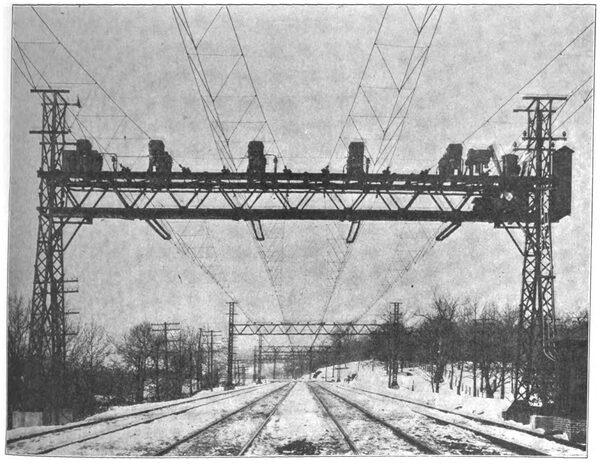
| Fig. 1. — One Ofthe Intermediate Bridges on the New Haven Road, Showing Semaphore Signals |
It is yet too early to furnish definite and positive comparisons of cost of the two methods under consideration, but the calculations and experience of the New Haven Railroad Company's engineers indicate that the total cost of a single-phase installation will be much less than that of the continuous current system, and that the higher electrical efficiency, lower fixed charges, maintenance and operating expenses of the single-phase system all tend to reduce the relative cost of current delivered to the engine shoes in about the same proportion.
The determination of the most economical and desirable frequency and voltage of the transmission system involved the consideration of many factors entering into the problem. The choice of frequency was practically fixed by the manufacturing companies within limits of 15 cycles and 25 cycles, and the comparative merits of these two rates only were considered.
The lower frequency afforded a material reduction in weight, size, and cost of motors, a reduction in conductor losses and induction disturbances, together with an increase in the power factor of the motors. Per contra, its adoption would have materially impaired the commercial value of the system, as a whole, in restricting or preventing its extension for many other uses incidental to railway operation. The standard power and railway frequency in general use is 25 cycles, and as the New Haven Company already owned a number of power houses generating current at this frequency for standard trolley operation, and, in addition, had equipped many of its shops with 25-cycle motors, the adoption of 15 cycles would have required the abandonment of a large amount of standard apparatus, or the interposition of costly and inefficient means of translation. The lighting of stations and other buildings was quite an important factor, as 25 cycles is the lowest frequency at which the carbon filament lamps in general use can be satisfactorily operated. It was also considered desirable to provide for operation in parallel with the 25-cycle generators already adopted by the New York Central Company. The practical effect of a change from 25- to 15-cycle apparatus was thus substantially equivalent to a "break of gage," and under existing conditions it was decided that the practical commercial value of the higher frequency outweighed the more theoretical merits of the lower one.
Various alternatives were considered before fixing the generating and transmission e. m. f. of the system. It was at first proposed to increase the economical radius of trans-mission to the utmost by generating current at the highest initial voltage for which generators could be safely designed (about 22,000 volts), and to provide sub-stations at suitable intervals, equipped with static transformers for supplying current at 3000 to 6000 volts to secondary contact circuits. As the two motors on each electric locomotive truck are permanently connected in series, current must be supplied at 560 volts through the transformer forming a part of the locomotive's equipment.
It became evident, however, that a great gain in simplicity would result if the intermediate sub-stations and line trans-formers could be cut out altogether, and further study demonstrated the possibility of effecting this by reducing the initial e.m.f. to 11,000 volts and raising the ratio of the locomotive transformer to correspond. This was carried into effect with a resulting reduction in capital and operating cost, coupled with an increase of electrical efficiency, which proved most gratifying. Incidentally, the difficulties in de-signing satisfactory collecting devices were greatly di-minished. The difficult and responsible task of determining and analyzing operating conditions and requirements was assigned to Calvert Townley, consulting engineer, and William S. Murray, electrical engineer, of the New Haven Company, to whom, together with their able assistants, credit is due for the design, supervision and successful execution of the many and difficult details of this novel installation.
THE COMMERCIAL ASPECT
A few comments upon the commercial aspects of electric traction may not prove uninteresting, as the natural prejudice of the stockholder in favor of the continued maintenance of dividends must be respected, and the technical expert too frequently neglects this aspect in his scientific ardor for the building of monuments of engineering skill and achievement.
Numerous analyses and comparisons of the comparative costs of electric and steam operation have been published from time to time, which tend to prove that a considerable saving in fuel, engine repairs and other operating expenses may be expected. Under favorable conditions this saving maybe large enough to pay interest and other fixed charges upon the additional construction investment and still leave a satisfactory margin to apply on dividends. Under general conditions, however, it is altogether improbable that the saving resulting from the simple substitution of electric for steam power will be sufficient to justify the additional in-vestment and financial risk.
In changing the method of motive power on existing railways, the conditions are by no means so simple as in the construction of new lines, as in the former case a great amount of capital already invested must be sacrificed, and the problems of adaptation to existing conditions are peculiarly severe. In particular, the transition stage in bridging over the gap between steam and electric operation is both expensive and difficult, as the change affects train lighting and heating, telegraph and telephone service, signaling, and track maintenance, for which both temporary and permanent provision must be made. The simultaneous maintenance of facilities and working forces for both steam and electric service within the same limits will be rarely profit-able, for the reason that a large proportion of expense incident to both kinds of service is retained, without realizing the full economy of either.
To secure the fullest economy it is necessary at least to extend the new service over the whole length of the existing engine stage or district, and to include both passenger and freight trains, and in this connection it is interesting to note that in the case of the New Haven Company the passenger train mileage forms so large a proportion of the whole that no additional generating and transmission capacity will be needed when electric traction is extended to freight service.
The application of electric traction to heavy railway serv-ice will probably be governed by other and more important considerations than its mere relative cost as a motive power under similar conditions, as illustrated in the development of the ordinary trolley service. In this development the commercial value of higher speeds and of increased car capacity is so large that the relative cost of electric versus animal tractive power becomes almost negligible by comparison. Analogous results may be hoped for in the corresponding development of electric traction in heavy railway service, as the new conditions will afford opportunities for at least two radical modifications of existing conditions, quite apart from minor economies.
In steam service the weight and speed of trains are limited by the horse-power capacity of the locomotive, which generates its own power, and there are but few locomotives which can generate sufficient steam to utilize their full cylinder tractive power at speeds in excess of 12 miles an hour. Consequently, any increase of speed beyond certain limits can only be attained by sacrificing train tonnage in a corresponding degree. The division of the train-mile cost by the lesser number of tons increases the ton-mile proportionately.
The high cost of fast freight service is principally due to this effect of a diminishing divisor, while it would seem that electric traction should permit high speeds without sacrificing commercial tonnage, as, with a relatively unlimited source of power at command, the maximum draw bar pull permitted by the motor design may be maintained at all speeds.
The commercial value of high speed in freight and passenger service is so great that the prospect of escaping the present penalties accompanying reduced train capacity be-comes doubly interesting.
| |||
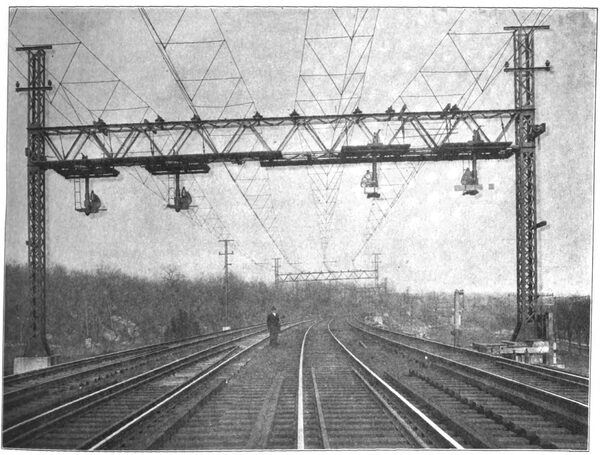
| Fig. 2. — Anchor Bridge Near Pelham Station, New Haven Railroad |
Hardly less important is the opportunity afforded at the opposite end of the scale, for the economical operation of trains of minimum capacity . The train capacity cannot be reduced without loss below the point where the earnings equal the train-mile cost, and if this cost cannot be reduced proportionately with reduced capacity, the inferior limit of capacity may be uneconomically large. In steam service the irreducible elements entering into the train-mile cost are so large that it is rarely profitable to operate trains earning less than 40 to 50 cents per mile. In contrast, electric service permits an extreme reduction of the train length to single car units, costing to operate but 10 to 15 cents per car-mile. Hence, the frequency of service may be increased and the rates reduced, which in turn will react upon the volume of traffic, with the final result of increasing both gross and net earnings.
It may, therefore, be claimed for electric traction that it will extend the limits of profitable operation of high-speed heavy trains, and also of light trains of low capacity.
Other but relatively minor advantages are possible in the effect upon earnings, due to the elimination of smoke, gases, dust, cinders and heat, the better ventilation of cars, the ex-tension of electric train lighting and heating, and of the effect upon expenses due to the concentration of power pro-duction in large and economical power houses, a reduction of engine repairs, an increase of effective engine and train mileage, a more or less complete elimination of engine houses, turn-tables, fuel stations, water tanks, cinder pits, and other operating facilities, the consolidation of power requirements for traction, pumping, operating shops, elevators, and general uses, and the use of current for lighting switch lamps, stations and other buildings.
Finally, the availability and value of real estate and structures at large terminals will be greatly augmented by the possibility of using two or more superimposed track levels, as strikingly exemplified in the plans for new terminals in New York City for the New York Central and the Pennsylvania companies.
A general change from steam to electricity will render unproductive a very large amount of invested capital, and create the necessity for the expenditure of additional amounts still greater, but there is no reason to doubt that the transition already in progress will be rapidly extended and applied to all points where congested terminals, high frequency of train service and low cost of power create favorable conditions.
THE OVERHEAD CONSTRUCTION OF THE NEW HAVEN
RAILROAD
The previous article by Mr. McHenry gives the reasons which lead the New Haven Railroad to adopt the single-phase system on its line from Woodlawn to Stamford. It is now proposed to publish a series of articles on the equipment as installed. The first of these articles will treat of the overhead construction.
 |
| Fig. 3. — End View of Anchor Bridge |
The electric trains of the New York, New Haven & Hartford Railroad leave the direct-current zone of the New York Central at Woodlawn, N. Y. , which is 12.03 miles from the Grand Central Station, and pass onto the alternating-current line of the New York, New Haven & Hartford Railroad, which at present extends as far as Stamford, Conn. Stamford is 33.48 miles from the Grand Central Station, and hence 21.45 miles beyond Woodlawn. Upon this section, between Stamford and Woodlawn, as has been stated, 11,000 volts are employed. The catenary construction, as well as the supporting bridges, have been illustrated and briefly described in the STREET RAILWAY JOURNAL on page 558 of April 7, 1906, and 595 of April 14 , 1906, when front elevations of the overhead bridges were shown, and on page 546 of March 30, 1907, when an account was given of the method of erecting the bridges. The information given then will not be repeated, but details will be published which were not available at that time.
OUTLINE OF OVERHEAD SYSTEM
The supporting bridges are of varying lengths, so as to accommodate four, five, six, or as many as twelve tracks, as the local conditions require, and are of two types, anchor bridges which are used only at intervals of about 2 miles, and intermediate bridges. The latter have side posts of square cross-section, and are of comparatively light construction. On the other hand, the anchor bridges have A-shaped posts and are made heavier to withstand the strain of the cables.
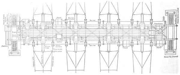
The anchor bridges are provided with automatic circuit breakers, by means of which the different sections may be isolated, and, also, the several parallel tracks may be electrically separated from one another in case of accident to any one track. The anchor bridges also carry lightning arresters, shunt transformers for operating the circuit breakers, together with foot walks, hand railings, lamp circuits and the wires and conduit for the auxiliary control circuits.
The working conductors have sufficient capacity for the current, but two auxiliary feeders are carried the entire length of the line from Stamford to Woodlawn. These feeders are connected with the main conductors at each anchor bridge through circuit breakers and provide means for feeding around any one section in case it is cut out of service on account of some accident in that particular section.
Provision is also made on all of the bridges for carrying two separate feeder wires called "power feeders," which are connected to the third phase of the generating system and are used for operating three-phase apparatus at certain intervals along the road. Provision is also made on the bridges for carrying two three-phase circuits, one circuit being supported on the top of each post at the ends of the bridges.
 |
| Fig. 4. — Plan of Anchor Bridge |
In laying out the bridges for the section from Woodlawn to Stamford, it was found that the sharpest curvature was 3 degs. As this curvature will permit of stringing the trolley wire in straight lines between points of support 150 ft. apart without deviating from the center of the track more than 8 1/2 ins. on each side, it was decided to place all bridges a fixed distance of 300 ft. apart, and on curves to provide guy poles to which pull-over wires are attached and secured to the catenary spans (see Fig. 1). By this means a minimum amount of overhead wiring was obtained, and the deviation from the center of the track was maintained within safe limits for use in connection with the sliding pantograph trolleys on the locomotives, the bow of which is 4 ft. long.
INTERMEDIATE BRIDGES
The general appearance of the standard four-track intermediate bridge is shown in Fig. 1. This illustration shows also signals mounted on the bridge, the semaphore blades being located below the truss so as to afford an un-obstructed view. As will be noted, the bridge consists of two supporting side posts and a horizontal truss. Each supporting post is approximately 38 ft. long by 1 ft. 10 ins. square. Each is composed of four 4 in. x 4 in. x 7/16 in. angles secured together by 2 1/4-in. x 3/8-in. lacing bars.
| |||
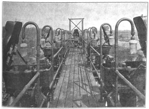
| Fig. 5. — View of Platform on Anchor Bridge, Showing Circuit Breakers on Either Side |
Each post rests upon a concrete foundation, each containing about 9 cubic yards of concrete. Anchor bolts ex-tend entirely through the concrete foundation and hold the base of the post to the foundation by means of heavy nuts. The cross-truss is attached by means of bolts to the vertical posts, allowing a distance of 23 ft. 4 ins. from the lower side of the truss to the top of the rails. The truss is 4 ft. 6 ins. deep from back to back of the upper and lower chord angles, which latter are placed 1 ft. 10 ins. from back to back. The lacing bars of the upper chord are depressed below the upper surface of the chord angles so that the latter are left free from rivets or other obstructions, thereby affording a ready means for attaching the insulators at any point. The lacing bars of the upper chord consist of flat strap, while the diagonals in the sides and bottom of the truss consist of angles. The upper chord angles are 3 1/2 ins. x 6 ins. x 3/8 in., and the lower are 4 ins. x 3 1/2 ins. x 5/16 in.
The extensions of the side posts above the trusses are utilized for supporting the feeder wires which are carried upon angle-iron cross-arms bolted to the posts. The lower cross-arm carries two insulators, upon the inner one of which is carried the auxiliary feeder. The upper cross-arm is located 5 ft. above the lower one and carries two wires of the three-phase circuit. The third wire of the three-phase circuit is carried upon a vertical angle-iron support.
 |
| Fig. 6. — Main Line Insulator With Supporting Yoke |
In the calculation of these bridges very heavy weather conditions were assumed and provision was made for clamping the catenary cables on the intermediate bridges so that they are obliged to partially withstand the longitudinal pull of the latter. It was assumed that the entire system of the bridges and cables might become coated with sleet, and that this coating might be ½ in. in thickness around all surfaces. It was assumed also that the wind pressure on the bridges and the catenary spans might at the same time be as high as 25 lbs. per sq . ft. It was further assumed that the effective area of all round cables would be two-thirds of their projected areas.
 |
| Fig. 7. — Strain Insulator for Deadening Cables |
Each catenary cable is clamped to its supporting insulator on every intermediate bridge, and it was assumed that if one pair of cables should be broken, the remaining cables would exert a balancing influence on the bridge. The truss, however, was made strong enough to prevent its buckling under the strain produced by the breakage of any pair of cables.
ANCHOR BRIDGES
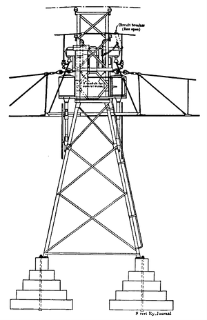
Anchor bridges of especial heavy construction are placed every 2 miles, and against these bridges the catenary cables are anchored. Fig. 2 gives a view of a standard four-track anchor bridge with the auxiliary apparatus mounted upon it. The four-track anchor bridge consists of two A-shape posts, each having a spread at the base of 15 ft., and a width at right angles to the track of about 2 ft. The main members of these posts consist of 6-in. x 4-in. x 5/8-in. angles. These posts are also extended above the truss in the manner shown in the illustration for the purpose of carrying the feeder wires. The truss is bolted to the side posts, allowing a clearance above the rails to the lower side of the truss of 24 ft. 3 ins. The truss is 4 ft. 6 ins. deep by 5 ft. wide between the backs of the chord angles. The upper chords consist of 8 in. x 8 in. x 9/16 in. angles, and the lower chords consist of 4 in. x 3 1/2 in. x 9/16 in. angles.
 |
| Fig. 8. — Details of Rigid Guy Pole |
Fig. 3 represents the side view of the anchor bridge, and Fig. 4 a plan view of the same bridge from which additional details of the construction may be noted. A ladder is provided on one of the posts leading to a small platform at the end of the truss. This platform is provided with a hand rail and carries upon it a box containing an 11,000-volt, low-equivalent lightning arrester. A portal is furnished in the end of the truss, by means of which the attendant may step onto the platform supported upon the lower chord of the truss. From this platform access is provided to the short ladders leading to the signal lanterns, and a second short ladder extending up to another 2-A platform supported upon the upper chord of the truss. This platform, a view along which is given in Fig. 5, is surrounded by a hand rail, which is also attached to the iron-supporting frames of the circuit breakers in such a manner that the attendant can in no way come in contact with live parts of the circuits. At each end of the truss a 5-kw 11,000-volt shunt transformer is provided, one of them being connected directly into a bus-bar which runs around the outside of the circuit breakers and which is supported upon porcelain insulators and bus-bar brackets, secured to the upper chords of the truss. The other transformer is connected directly into one of the "power" feeders. As the "power" feeder is connected to the third phase of the generating system, means are available for operating the switches in case of accident to the trolley section. The four-track anchor bridge is secured to concrete foundation by means of long anchor bolts and nuts. Each post rests upon blocks of concrete, each block containing about twelve cubic yards of concrete.
 |
| Fig. 10. — Pull-Off Hanger |
 |
| Fig. 11. — Insulating Separator |
CATENARY CABLES
Each of the two catenary cables which support the cop-per trolley conductor consists of an extra high-strength steel cable, 9/16 in. in diameter, consisting of seven strands .This steel has an ultimate strength of about 200,000 lbs. per square inch, and each strand is heavily galvanized. The completed cable has a total strength of 33,800 lbs. These cables are strung between the bridges with a sag at mean temperature of6 ft. in a standard span of 300 ft. Owing to obstructions at certain places along the right of way, the spacing of the bridges is occasionally varied from the standard distance of 300 ft. In order to allow for this the cable is run out in long lengths and is pulled up to a uniform tension until the sag in the span of 300 ft. is 6 ft. The sag in the other spans is allowed to adjust itself, since the tension is the same. After being pulled up to the proper tension the catenary cables are anchored to the anchor bridges and are clamped to the insulators of the intermediate bridges.
 |
| Fig. 12. — Trolley Hanger |
MAIN-LINE INSULATORS
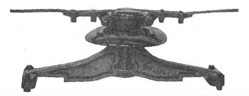
The insulators which support the catenary cables of the intermediate bridges consist of heavy porcelain insulators of the skirt type, which are 15 ins. in diameter and about 7 ins. high. These insulators are cemented upon short lengths of double, extra strong pipe, which in turn is held by means of U-bolts to a cast-iron yoke, bolted to the upper chords of the truss. The catenary cable rests in a groove in the top of the porcelain and is held by means of a malleable-iron clamp fitted with U-bolts and placed one on each side of the insulator. The head of the insulator is conical in shape and is surrounded by means of a split malleable-iron clamp and a lead packing. Fig . 6 represents the main line insulator complete with its supporting yoke.
 |
| Fig. 9. — Details of Anchored Guy Pole |
One feature of the construction to be noted is the arrangement of the clamp and the collar, which is such that in case of the breakage of the messenger cable on one side of the insulator, the pull of the cable on the other side will cause the clamp to swing downwards, thereby lowering the point of application of the pull of the cable. Thus the porcelain is put in compression, and there is no tendency to shear off the top of the porcelain, as is usually the case with porcelain line insulators. Each porcelain is subjected in the shop to a test of 55,000 volts when assembled.
ANCHOR BRIDGE STRAIN INSULATORS
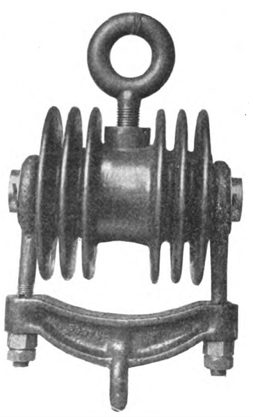
Fig. 7 represents the general appearance of the strain insulators which are used for dead-ending the catenary cables at the anchor bridges. These insulators, which are of special construction, are designed to withstand a shop test of 50,000 volts and a working load of 20,000 lbs. Each consists of a length of 2 in. extra heavy iron pipe, surrounded at its middle point by an iron collar. Outside of this collar a long insulating tube, composed of especially hard and reliable insulating material, is pressed. This tube is surrounded by a second collar into which a bolt is screwed and to which turnbuckle of the catenary cable is attached. The entire surface of the insulating tube and the inner and outside collars are then effectively sealed against moisture by means of a high-grade insulating compound applied by means of hydraulic pressure. The insulator thus made up is supported by means of an iron yoke from cast-iron hooks bolted to the upper chords of the anchor-bridge truss.
One of these insulators is provided in each catenary cable at each anchor bridge, thereby electrically dividing the road up into separate sections between the anchor bridge.
GUY POLES
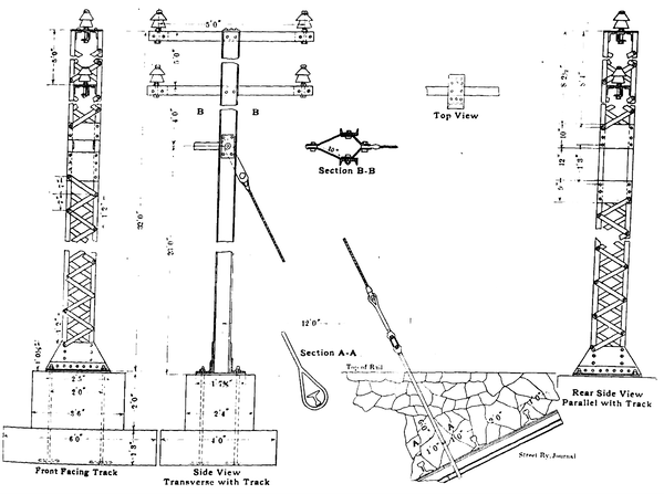
Midway between the supporting bridges and curves a guy pole is located on the outside of the curve. These guy poles are of two types, namely, rigid and anchored, the former being used wherever there is room on the right of way for the anchorage, while the latter is used in places where the width of the right of way is restricted. Fig. 8 represents the rigid pole, and Fig. 9 indicates the type of anchored guy pole. A pole of the latter type is seen in place in Fig. 1.
 |
| Fig. 13. — Section Insulator |
Heavy strain insulators are attached to the guy poles at the proper height, and pull-over wires are attached to this strain insulator and to the catenary cable and trolley wires of the several tracks.
GUY-POLE STRAIN INSULATOR
This insulator is somewhat similar in appearance to the well known "giant strain," except that it is designed to withstand a test of 50,000 volts, and a mechanical pull of 15,000 lbs. It is made up of steel castings and solid mica insulating cones and is sealed with a high-grade insulating compound. These strain insulators are attached by means of one loop in the guy poles, and the pull-over wires are attached to the other loop.
 |
| Fig. 14. — Oil Circuit Breaker for Bridges |
PULL-OVER HANGER
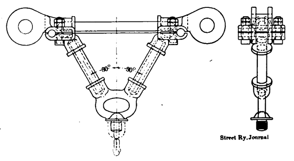
At the points where the pull-over wires are attached to the catenary span (Fig. 1), a triangular hanger of heavy construction is provided. The character of this hanger, which is indicated by Fig. 10, consists of malleable-iron clamps, which are attached to the two catenary cables, and into which short lengths of heavy pipe are threaded. At the lower end of the triangle is provided a malleable-iron casting, which is threaded into a heavy bronze clamping ear which is attached to the trolley wire. Loops are provided as shown for attaching the pull-over wires in such a manner as to hold the trolley wire directly under the catenary cables.
INSULATING SEPARATORS
In order to enable any one track to be electrically disconnected from any other parallel track when the circuit breakers on the anchor bridges are open insulating separators are provided in the pull-over wires between the tracks (see Fig. 1.) The appearance of these is shown by Fig. 11. They consist of 5-ft. rods of selected hickory, thoroughly impregnated and fitted at the ends with malleable-iron heads secured to the conical-shaped heads of the rods by means of bolts. Each insulator has an ultimate strength of about 16,000 pounds. At no point in the entire construction is wood relied upon for insulation to ground, and it will be noted that these wooden separators normally have no difference of potential upon them. They are merely provided in case of accident, when it is necessary to isolate one section of track from another. They are, however, subjected to a test of 30,000 volts.
 |
| Fig. 15. — Details of Oil Circuit Breaker |
TROLLEY HANGERS
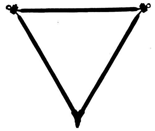
The trolley wire is supported from the catenary cables at 10-ft. intervals by means of triangular trolley hangers of varying lengths. These hangers are so adjusted in length that the trolley wire is maintained in a horizontal position (Figs. 1 and 2), it being 6 ins. below the catenary cables at the middle point of the span. The appearance of a hanger is shown in Fig. 12. It consists of a pair of small drop-forged steel jaws, which engage with the grooves of the trolley wire and are clamped by means of a malleable iron Y, which is screwed down upon the threaded portions of the jaws. The sides of the triangle are then screwed into the Y and are bolted to the messenger cable above. As all of the threads are right handed, it is impossible for the hanger to come loose.
TROLLEY SECTION BREAK INSULATORS
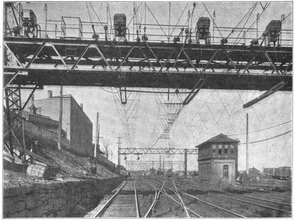
At each anchor bridge it is necessary to provide an insulator in each trolley wire, and this is accomplished by means of the piece of apparatus shown in Fig. 13. Each consists of two bronze end castings, to which the ends of the trolley wire are bolted. Two parallel sections of impregnated hardwood are fastened to these castings, and to these wooden strips are fastened renewable pieces of trolley wire in such a manner that the ends of these renewable pieces overlap one another in distance along the track, although the two wires are electrically distinct. By this means it is possible for the sliding contact on the locomotive to pass from one section to the next without opening the circuit, thus avoiding all flashing. It will be noted, however, that an effective insulation is provided so that when the circuit breaker on the anchor bridge is open, the two sections will be disconnected. The manner in which this section insulator is installed is clearly shown in the end view of the anchor bridge, Fig. 3. Insulators in place under an anchor bridge are shown in Fig. 2.
LOW-BRIDGE CONSTRUCTION
This construction consists of a corrugated porcelain spool, mounted on a length of gas pipe, which in turn is supported at each end from a skirt type porcelain insulator of the same design as that used on the intermediate bridges. An insulating support of this character is mounted on each side of the overhead bridge and is located so that it will receive the washing effect of rainwater and be kept clear of soot accumulation.
 |
| Fig. 16. — Twelve-Track Overhead Bridge |
The messenger cables, where they pass under the bridges, are heavily insulated and are secured to the porcelain spools just described. The trolley wire is suspended from the messenger cables by means of hangers, constructed of impregnated hardwood, so that the trolley wire is isolated from the catenary cables.
A waterproof shield above the cables prevents the accumulation of dirt and water upon them.
TROLLEY WIRE
The trolley wire consists of standard No. 0000 B. & S. gage grooved copper.
AUTOMATIC CIRCUIT BREAKERS
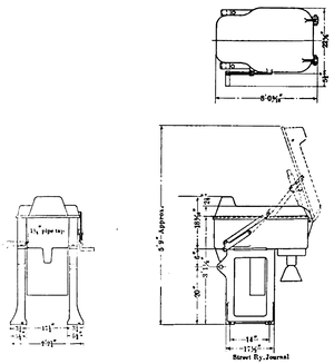
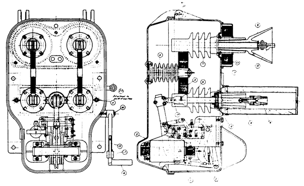
Fig. 14 represents in outline the type of circuit breaker which has been developed for this installation, while Fig. 15 gives the details of the device, and Figs. 2 and 5 show the breakers in place on anchor bridges.
The breaker consists of a cast-iron framework adapted to be bolted to channel irons resting upon the upper chords of the anchor bridges. This framework carries an iron box provided with a hinged cover. This cover is arranged to fit tightly in place so as to exclude all rain and snow and be entirely weather-proof. The moving parts of the circuit breaker are contained within this box and are made especially rugged and reliable in their operation. The terminals of the switch are brought out through specially con-structed insulators mounted in an overhung portion of the box at the rear (Fig. 15). Upon the tops of insulators are carried knife-switch jaws, and there are corresponding jaws mounted on the upper ends of the circuit breaker contacts. Two switch blades are carried on insulating pillars fastened to the hinged cover of the box in such a manner that when the cover of the box is closed one terminal of the switch is connected to the bus-bar on the anchor bridge and the other is connected to the trolley wire. Arrangements are provided so that if the cover is opened the circuit breaker will be automatically tripped so as to prevent any possibility of the attendant taking hold of live parts.
 |
| Fig. 17. — Section Insulator for Turnouts |
The circuit breaker is capable of handling 11,000 volts on heavy, short circuit. A tripping coil is provided, together with closing magnets, both of which are operated from a circuit supplied from the small shunt transformers on the anchor bridge. The switch is also arranged to open automatically on overload.
The control wires for the closing magnets and the tripping coils are carried in iron conduit and lead-covered cable to the adjoining signal tower, where a switchboard panel is provided. This panel is fitted with switches so that any circuit breaker may be tripped by hand, or closed by the attendant in the signal tower. There is also a switch by means of which the attendant may connect either of the shunt transformers on the anchor bridge to the control circuit.
| |||
| Fig. 18. — Deflector Wires in Place Between the Main Trolley and Cross-Over Trolley |
AUXILIARY FEEDERS
The auxiliary feeders, which are supported on the inner insulators of the lower bracket arm on the bridges, are looped in to the bus-bars on each alternate anchor bridge. These connections are made through automatic circuit breakers, so that in case of the grounding of the bus-bar structure to any anchor bridge, one of the auxiliary feeders will pass around the grounded bridge to the next section beyond. On each anchor bridge one auxiliary feeder is broken by a strain insulator, and connections are made through circuit breakers to the bus-bar. The other auxiliary feeder is carried directly through, and a single tap connection is made from the feeder through the circuit breaker to the bus-bar. Upon the next bridge these conditions are reversed, so that each auxiliary feeder is divided into 4-milesections. This arrangement provides a maximum flexibility of control.
YARD CONSTRUCTION
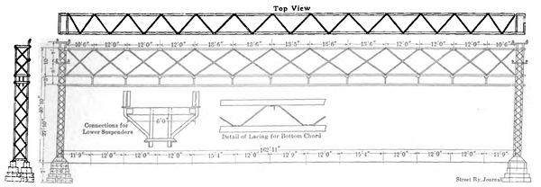
At a number of points along the road, where there are numerous side-tracks, it is necessary to provide extra long bridge supports. Fig. 16 represents one of these long bridges, which is designed to cover twelve tracks. The catenary cable insulators are attached to the lower member of the truss.
TRACK BONDING
Both rails of all tracks are bonded by means of No. 0000 compressed terminal flexible bonds placed around the fish-plates.
TURN-OUTS AND CROSS-OVERS
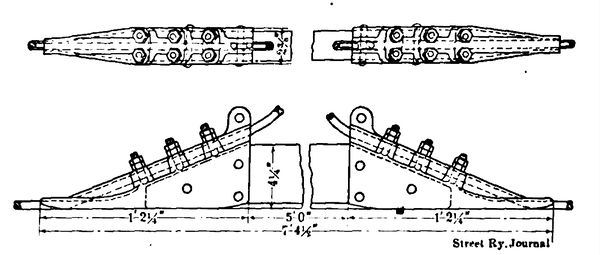
Whenever one track diverges from another a section insulator shown in Fig. 17 is inserted in the trolley wire. Insulators like Fig. 11 are inserted in the catenary cables sup-porting the diverging wire between parallel tracks. The diverging trolley wire is connected to the main wire by means of a frog of standard design, and in order to prevent the contact shoes on the locomotive from catching, deflector wires are placed in the angle between the trolley wires. These deflectors are carried by yokes scured [sic] secured to the trolley wire and to a yoke at the rods fastened to the catenary hangers. These deflectors are raised at each end so that the collector shoe cannot catch on them. The arrangement is shown in Fig. 18, the details being given in Fig. 19. There being a certain amount of flexibility in the overhead trolley system, when the bow is pressed upward against the contact wire, this wire is raised above the level of the other contact wires in the immediate neighborhood. Thus, certain portions of the short length of trolley wire used to interconnect the two main trolley wires at cross-overs would tend to remain in a plane below that of the active trolley wire as the locomotive passed this point. The deflector wires are designed to tend to cause the cross-over trolleys and the main trolley to be raised partly in unison by decreasing the upward movement of the main trolley and increasing the upward movement of the cross-over trolley. The contact bow of the trolley mechanism on the locomotive is given a certain amount of upward curvature towards the center, so that the bow has no tendency to catch in either the cross-over trolley wires or the intermediate deflector wires.
DRAW-BRIDGE CONSTRUCTION
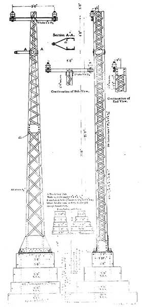
An interesting piece of special work is indicated in Fig. 20, which shows side and end views and constructive details of extra high steel towers used at the Cos Cob drawbridge. These towers enable the transmission and trolley wire circuits to be elevated about 115 ft. above the high-water level when crossing the stream at the point mentioned.
 |
| Fig. 19. — Overhead Construction at Turnouts |
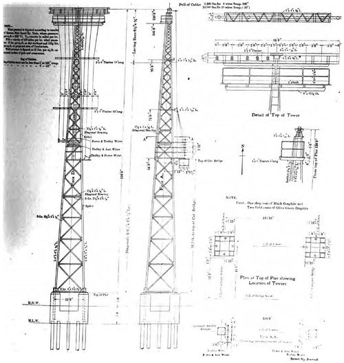 |
| Fig. 20. — High-Tower Work at Cos Cob Bridge |
LOCOMOTIVES
Two longitudinal sections, with key of parts, of the locomotive used are published on the inset between pages 246 and 247. Further details of these machines will appear in an early issue of this paper, together with an account of the power station at Cos Cob, from which the power for the alternating-current section of the line is obtained.
CONTRACTORS
The contractors for the electric locomotives, catenary construction and turbo-generators used in the power sta- into [sic] station were the Westinghouse Electric & Manufacturing Company, and for the rest of the power house equipment and power station itself, Westinghouse, Church, Kerr & Company.

