[Trade Journal]
Publication: Sibley Journal Of Engineering
Ithaca, NY, United States
vol. 11, no. 1, p. 3, col. 1
TEST OF RAILWAY INSULATORS.
L. A. MURRAY, '94.
The following is a report of a test of some glass and porcelain railway insulators made last year in the Electrical Engineering laboratory, by H. O. Pond, '96, working under the direction of Professor H. J. Ryan. The insulators were manufactured by F. M. Locke of Victor, N. Y. , and were especially designed for railway work, the chief feature being the two circular walls or petticoats inside of the main shell of the insulator. The object of these walls is to make the surface, over which leak current must pass as large as possible. The tests were made with pressures varying up to 51,000 volts. These high voltages were obtained from the high potential transformer built in Sibley College in 1895.
Current for the work was obtained from the University lighting plant at 100 volts pressure. This was then stepped up by means of a 41-116 transformer to 282 volts, which was the pressure impressed on the primary of the high potential transformer. The transformation ratio of the latter is 140-30000. A variable resistance was placed in the primary of the first transformer, and an automatic circuit breaker in its secondary to prevent burn-outs in case of short circuits. The pressure on the primary of the small transformer was varied by changing the resistance in series with its primary, and an ordinary Weston voltmeter was used to measure the pressure of the high tension transformer's primary. The secondary pressure of the high pressure transformer was found from the ratios of transformation of the two transformers. For the purposes of the test, two insulators, one of porcelain and one of glass, were mounted in parallel, one terminal of the secondary of the transformer being connected about the necks of the insulators, while the other was attached to their supporting posts. The post was of the ordinary form used with such insulators, consisting of a wrought-iron rod, surmounted by a wooden screw. The necessary height above the cross-arm or other support is obtained by means of a cast-iron bracket.
Four tests were made, but the phenomena occurring in one will be described, as the action seemed to be similar for all cases. All tests were conducted in a darkened room, in order to facilitate the observation of the phenomena of the discharge of current over the insulators. In all cases the test was started with the pressure at a comparatively low value. This was gradually increased until the insulator broke down, or the limit of the transformer was reached. The first tests were made upon insulators which had been carefully cleaned and dried. Upon closing the primary circuit, no effect was observed until the 9,000 volt mark was reached, a slight violet colored discharge, was observed coming from the top of the iron support on the inside of the glass insulator. At 18,000 volts, this discharge had become quite violent, and another was observed around the line wire on the outside of both insula tors. The pressure was gradually increased to 24,000 volts, when a yellow spot resembling an arc was observed at a point on the neck of the porcelain insulator, indicating a weakening of the porcelain. At 24,700 volts the porcelain insulator was punctured, and the pressure immediately fell to 15,000 volts. At this point, occurred another puncture, followed by violent sparking, the current soon burning a passage of sufficient size to short circuit the transformer. Upon breaking open the ruptured insulator, it was found that the porcelain was not homogeneous, and that the breakdown had occurred through the neck where the section was the thinnest. The arc had followed the grain of the porcelain, the path being shown by the blackened material. Three other insulators were broken down in the same manner and the results are given in the table below. The maximum pressures on the insulators are 1.4 times the observed pressure.
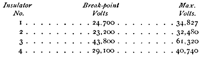 |
The grain in Nos. 3 and 4 was finer and closer than that of the other two. From the results of these tests it would seem that these insulators were not made thick enough at the neck, as all breakdown is occurred at that section. The chief resistance to the passage of the current seemed to be in the surface glazing.
It was not found possible to break down the glass insulators even by subjecting them to a pressure of 51,000 volts. This was done by thoroughly insulating the iron support from the insulator, in order that there might be no discharge from the transformer terminal to the support. The insulator seemed to act, at these high pressures, much like a condenser. Other experiments were tried in which the surfaces of the insulators were dampened about as much as would be caused by a heavy fog. Under these circumstances, a short circuit was obtained from the outside surface of the glass insulator to the supporting post at about 19,500 volts. A short circuit appeared on the porcelain insulator at about 21,000 volts. In no case did the discharge follow around the surfaces of the petticoats. From the foregoing experiments, it would seem that when dry, glass is a better insulator than porcelain, probably because of its greater homogeneity. The efficiency of glass as an insulator is, however, very much reduced in damp weather. The results of these tests would also indicate that the resistance offered to the current in passing over the surface of the insulator to the supporting post, should be equal to that offered by the air-gap from the edge of the insulator to the supporting post.
In order to determine the amount and phase position of the currents which leak over the insulators, the following method, devised for this work by Prof. Ryan, was used. In general, the method is to run the high potential transformer with its secondary open in order to find the magnetising current, and then to close the secondary through the insulators and again determine the current. The magnetising current of the transformer not being in unison with the impressed E. M. F. of the primary, it is necessary to find the component of current which is in unison with it and also to find the value and position of the other component which is at some unknown angle to the first. One component is easily found by means of a watt-meter and a volt-meter. To find the other component, Prof. Ryan has resorted to the following expedient: The primary of an ordinary transformer is put in series with the secondary of another transformer which we will call (A). In series with the secondary of the second transformer which we will call (B) are placed a lamp and the fine wire coil of a "hedgehog" transformer. Now, the E. M. F. in the secondary of the second transformer (B) is 180° from the E. M. F. impressed on the primary of the high potential transformer, since its primary pressure is the same as that of transformer (B). By reason of the self-induction introduced into the circuit by the "hedgehog" transformer, this secondary E. M. F. is changed to a position at about 90° from the primary E. M. F. The exact angle between these E. M. F.'s is determined by means of a triangle of E. M. F.'s, the values for which are obtained by the three volt-meter method of measurement. For this purpose the non-inductive resistance is placed in the secondary circuit of the second transformer (B). The necessary measurements are: the E. M.F. impressed on the line transformer, the drop through the lamp, and the total E. M.F. From these values, the triangle of E. M. F.'s giving the relative positions of each E. M.F. may be constructed. Then knowing that the current through the lamp is in unison with its E. M.F., and also the value of the current in unison with the primary impressed E. M. F., the value of the magnetising current is represented by the diagonal of the parallelogram of which the two current values are the two sides. The positions and values of the currents for open and closed circuit being determined, the leak current is found by taking their geometric difference. That is, the current flowing (when the secondary is closed through the insulators), is the magnetising current plus the leak current, and is therefore represented by the diagonal of the parallelogram. One side of this parallelogram represents the magnetising current, and the other side the leak current which is sought.
In making the test, a number of insulators, corresponding to about one-half mile of line, were put up in the usual way on 36 inch wooden cross arms. The wires were connected up to resemble an ordinary line with metallic return on open circuit, one being connected to each terminal of the high pressure transformer. The apparatus was connected up with suitable resistance, switches and circuit breakers to regulate pressure and avoid burnouts. The transformer was first run on open circuit; that is, the insulators were not connected in. Measurements were then taken of the primary watts, primary E. M. F., the fall of potential through the lamp, the watts taken up in the lamp, and the total E.M.F. The insulators were then put into the secondary circuit and a similar set of readings taken. Runs were made with two differ pressures on the insulators -- one of 17, 100 volts and the other of 22,500 volts.
It was found that the leak current had the phase position of a condenser current; that is, it was almost 90° ahead of the E. M.F. With the higher pressure the angle was found to be somewhat diminished, but the power factor was still very small. Further experiments along this line will be undertaken during the present year and it is expected that a great deal of valuable data will be obtained.
