[Trade Journal]
Publication: Western Electrician
Chicago, IL, United States
vol. 32, no. 21, p. 395, col. 1-3
Latest Developments in Central-station Engineering in Chicago.
To the student of electrical progress the development of the central-station industry in a large city like Chicago is a subject of absorbing interest. The marvelous growth of the business of supplying electric light and power, the difference in the size and type of the machinery used in the generating systems of, say, 1891 and 1903, the automatic methods of handling coal and ashes, the evolution of transmission and distribution systems, the appearance of the alternating current for local transmission and the introduction of the rotary sub-station, the increased use of the storage battery, the greatly augmented complexity of all financial, administrative and engineering problems involvedthese are some of the characteristics of the history of electric lighting in any large city of the United States, and particularly in Chicago, during the last dozen years.
| |||
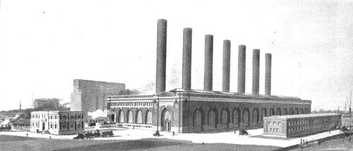
| Fig. 1. Office Building. Boiler House and Turbine House. Switch House. Latest Central-Station Developments in Chicago. Fisk Street Station, Now Building, As It Will Appear When Completed for Ultimate Capacity of 70,000 Kilowatts. |
As readers of the Western Electrician are aware, the central-station industry of Chicago is in the hands of the Chicago Edison Company and the Commonwealth Electric Company. A number of articles have appeared in this journal, from time to time, descriptive of the growth and development of the plants of these companies. In the New Years issue of I902 the Western Electrician described the installation of the first of three very large reciprocating-engine 'and alternator units which were being placed in the Harrison Street station of the Chicago Edison Company, and also mentioned other additions and extensions of the two companies. This was followed later in the year by a description of the large new Randolph Street rotary-converter sub-station. It is the present intention, in a survey of the whole interlaced systems of the two companies, to bring the description up to date, with some reference to radical innovations in the design of the Fisk Street station that have attracted widespread attention.
HARRISON STREET STATION.
Ten years ago the Harrison Street station of the Chicago Edison Company, which supplies current to both the Edison and Commonwealth companies, and is now the largest generating station in the city, was first put into operation. At that time it was considered that this station would be large enough to supply the companies' demands for many years to come. There was then installed a total of seven boilers and to engines, the engine capacity being considerably in excess of the company's maximum demand. During the 10 years that has passed, the original building has not only been filled up with a type of generating units entirely different from that originally contemplated, but every inch of ground has been covered with additions, until now the plant has an overload capacity of about 19,000 kilowatts, not including the storage battery on this particular property, which has a capacity of 17,000 ampere-hours at the rate of eight hours discharge. Fig, 2 is a diagrammatic plan of the Harrison Street station, showing the additions since its original installation. It gives an interesting commentary on the growth of the system.
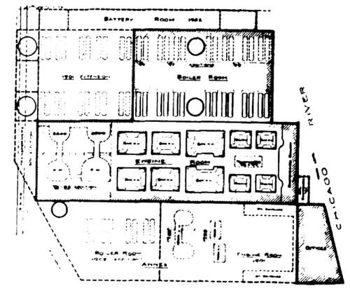 |
| Fig. 2. Block Plan of Harrison Street Station, Showing Accretions. |
| |||
| Fig. 3 Harrison Street Station of Chicago Edison Company. |
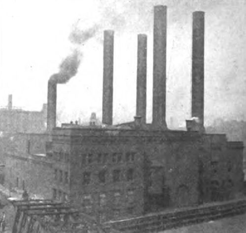
During the last year there have been some improvements and additions to the Harrison Street plant. The boiler capacity has been increased by the addition of four new Babcock & Wilcox boilers located in an addition on the south side of the original engine room and on the opposite side of building from the original boiler room, as shown in Fig. 3, which is a view taken from the southeast, and which indicates that the entire property is now covered by buildings. These additional boilers meant an entirely separate boiler room with separate facilities for handling coal and ashes. The four new boilers each have 5,000 square feet of heating surface and are equipped with Babcock & Wilcox chain-grate stokers. The steam piping is so arranged that these four boilers supply a separate header which, in turn is connected with the main steam header in the original boiler room. From this separate header the connections arc made to the engines in what is known as the annex engine room. The new stack, which is the fifth in the building, will, when completed, be 170 feet high. There is also in process of erection a new 32 and 64 by 60-inch vertical cross-compound Allis-Corliss engine running at 75 revolutions per minute. This will be direct-coupled to a 40-pole, 1,800-kilowatt, 25-cycle, revolving-field, 9,000-volt General Electric alternator. The condensing equipment for this unit consists of a jet condenser and a 24 and 48 by 24-inch Dean air pump.
The high-tension switching apparatus is being considerably enlarged and improved to take care of the increased generator capacity and the increased number of transmission lines from this plant. When completed, the generator and feeder oil-switch equipment will be divided and installed in three entirely separate and independent fireproof rooms, the arrangement of generator and feeder connections being such that the 9,000-volt generators Lan be run in a number of independent sections or all in multiple.
Moreover, the isolation of this apparatus is such that it is practically impossible for the entire 9,000-volt system to be shut down, no matter what the accident might be.
WASHINGTON STREET STATION.
This station (at Washington and Market Streets) was designed originally for a large number of series arc machines and some small 500-volt and single phase generators, driven from three lines of shafting. It has been increased and rearranged, so that it now has a rated capacity of 4,500 kilowatts in direct-coupled generators feeding into the Edison network. This consists of one 1,500-horsepower and four 600-horsepower tandem-compound Southwark engines, driving 300-volt and 150-volt direct-current generators. Two of the 600-horsepower and one 1,000-horsepower Williams engines formerly driving line shafting have been equipped with direct-coupled direct-current generators. Work of similarly equipping another 600-horsepower Williams engine is under way. Within a few weeks the last remaining portion of the line shafting will be shut down, the series arc having been replaced by constant-potential lamps, the few remaining 500-volt generators being driven by 250-volt motors and the single-phase alternating-current load transferred to new frequency-changing motor-generator sub-stations. This transformation to direct-coupled units delivering current to Edison network exclusively will probably mark the beginning of the last chapter in the history of one of the pioneer stations of Chicago, as the Washington Street plant was originally the station of the old Chicago Arc Light and Power Company.
RAPID GROWTH OF SYSTEM.
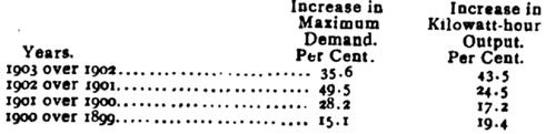
How necessary were the additions at Harrison Street and how the demand on the company's generating capacity has increased may be noted by the following figures, which show the increase in maximum demand and total kilowatt-hour output on the system from 1898 to 1903:
 |
THE FISK STREET STATION.
A careful consideration of these increases and an estimate of the probable future rate of increase made it apparent that additional generating capacity should he supplied, and that the addition should not be a small one and a temporary expedient, but should be of considerable magnitude and of such capacity as to provide for any great amount of increase that might take place in the next few years. The situation was thoroughly canvassed and studied in every detail. A number of locations were considered, and finally a site was secured on the South Branch of the Chicago River near Fisk and Twenty-second Streets, as indicated by (18) in Fig. 4. This site is about 3-1/2 miles from the electric center of the total load of the two companies, which is a point that is continually shifting, but is within two blocks of the intersection of Clark and Monroe Streets. The property secured consists of about 14 acres of ground, divided into two portions, as indicated on the map, Fig. 5. The larger portion, consisting of about 13 acres, is situated on the north bank between two slips of the river, which at this point runs almost in a westerly direction. The smaller portion is located directly opposite on the south bank of the river.
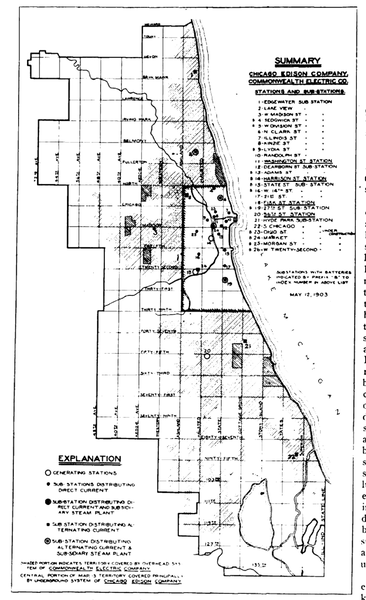 |
| Fig. 4 General Map of Central and Sub-Stations in Chicago. |
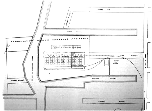 |
| Fig 5. Map of Fisk Street Property. |
On this site the Commonwealth Electric Company decided to erect a central generating station that should be of ample capacity and which should embody the most modern ideas in central-station practice. A very important consideration in the location of the plant at this point was the fact that the real estate was secured where it was commercially feasible to adopt the very best arrangement of apparatus that could be had, the supply of condensing water and facilities for handling and storage of coal also being excellent. No pains were therefore spared to design the station in all its details, so that the highest possible coefficient of reliability could be obtained. The result is that the station as now being constructed will embody features which in some instances will mark a radical departure from the ordinary central-station practice, but which, on the other hand, have been very carefully thought out and sanctioned by the best of engineering ability. A general perspective view of the new station as it will ultimately appear, looking southeast, is given in Fig. 1. On the left is represented an office building that may eventually be built and on the right the switch house.
GENERAL CHARACTERISTICS OF FISK STREET STATION.
After the subject had been worked over pretty thoroughly, it was finally decided to design a plant which would ultimately contain 14 turbo-generator units, rated nominally at 5,000 kilowatts each. This building would be divided into seven bays, each containing two units, as shown in Fig. 5. The first two bays are now under construction. The building however, is so designed that in case it is later found advisable, reciprocating engines can be installed in the remaining five hays. This would mean that the engine room, or turbine house, as it is called, would have to be widened somewhat, but there would be no change in the boiler-house portion or in the height of the roof of the engine-room portion.
The development of the system of high-potential generation and transmission has been such that by next fall the Edison and Commonwealth companies will have in service about 60 miles of 9,000-volt, three-phase 25-cycle transmission lines. This will supply current to sub-stations aggregating about 24,000 kilowatts in rotary converters and about 4,000 kilowatts in frequency-changing motor-generator sets.
The experience in Chicago and other large cities has demonstrated that there is a practical limit to the amount of high-tension cable which at time of heavy load should be operated in parallel as a single interconnected network. The extension of the transmission and sub-station system during the last two years has been carried on with the idea that at a very early date the system would be sectionalized, and, furthermore, that the new Fisk Street station could be arranged so that the units could be operated independently. So completely has this been worked out, that, beginning with an independent coal conveyor, boilers, steam piping, generating units and condensing plant, sectional bus-bar and separate transmission lines from each unit feeding sub-stations, there may be absolutely independent operation of every link between coal pile and interconnecting street mains or direct-current sub-station bus-bars. Moreover, all the large sub-stations are supplied from at least two different generating units.
This plant, therefore, consists essentially of 14 plants of 5,000-kilowatt rated capacity each, located end to end. It secures therefore, all the advantages of a large plant in having a minimum of unproductive labor involving less unproductive investment, securing a very economical and reliable arrangement in the handling of coal and condensing water. By independent or sectional operation it also secures practically all of the advantages that might be claimed with the use of a number of smaller plants.
DESCRIPTION OF FISK STREET STATION BUILDING.
The building, as shown in the plan, Fig. 5. is divided into three sectionsthe boiler house, with batteries of boilers extending east and west the turbine house at the west of boiler-house section. extending north and south, and the coal-receiving house on the east of the boiler house, extending north and south, thus forming a unit of construction of the batteries of boilers, one generating unit and the coal-handling machinery, in the direction of east and westthis unit to be repeated in the direction of north or south, as requirements may demand, for additional capacity. The completed building will be 600 feet long and 230 feet wide. The exterior of the building is designed in red pressed brick with cut-stone trimmings. There are large window openings, designed in ornamental iron, with pivoted sash for complete ventilation.
The interior of the boiler house is designed with glazed brick and terra-cotta wainscoting eight feet high, the balance of the walls being of pressed brick. The coal-receiving shed, being open to the architectural treatment. The floor is to be laid in vitrified German tile, of small size, laid in pattern to give a general mosaic effect. On each side of the turbine house there is a narrow gallery extending the full length of the room, constructed of ornamental iron, and with tile floors. The switchboard gallery is two stories in height, with ornamental staircases, switchboard frame, etc.
The main entrance to the turbine house is of such design as to allow of a car being run into the room for the delivery of machinery, and unloaded by the cranes, which travel the full length of the room.
The group of illustrations shown in Figs. 6, 7, 8 and 9 is of construction views of the station taken at intervals during the last four months. Fig. 7 is a view taken on February 13th and shows the steel skeleton framework of the building, with the turbine house on the left. Fig. 8 was taken on March 8th and represents the north end of the structure. Figs. 9 and 6 are birdseye views of the station, taken, respectively. on April 16th and May 8th. The latest one shows foundations for walls and columns and gives a good idea of the extension of the building.
BOILERS.
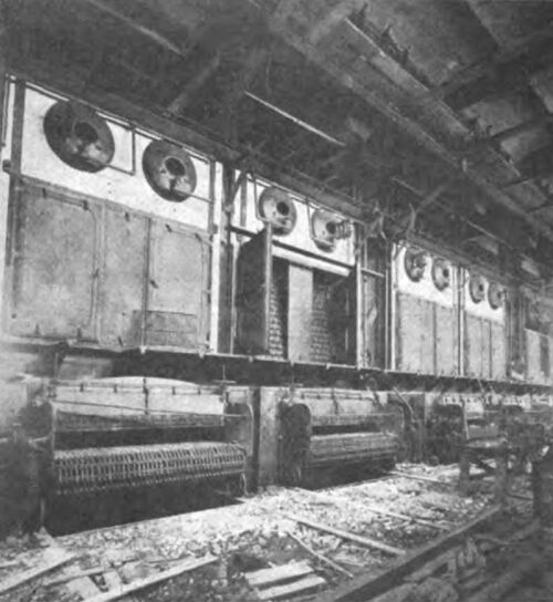
The arrangement of the steam plant is such that eight boilers constitute one unit of boiler house, and are set up on a line at right angles to the line of turbines, that is, eight boilers directly opposite each turbo-generator unit. This is a radical departure from the conventional method of setting lines of boilers parallel to the line of engines. In this particular installation all boilers are set on one floor, this floor being on a level with the floor of the gallery that passes around the turbine room. The boiler-house units at each end of the plant will have an independent firing space. In all the intermediate units a single firing space will be common to two rows of boilers. Each boiler-house unit consists of eight Babcock & Wilcox water-tube boilers having 5,000 square feet of heating surface and equipped with super-heater and Babcock & Wilcox engine-driven stoker. The boilers generate steam at 175 pounds' pressure with 150 degrees of superheat. One of these sets of boilers is now practically completed as may be seen in Fig. 10. There will be one stack for each two boiler-house units, making a total of seven stacks for the completed plant. These stacks are 205 feet high above the boiler-room floor and feet in diameter.
| |||
| Fig. 10. A Row of Boilers at Fisk Street Station. |
COAL HANDLING AND STORAGE.
Coal is brought into the building in hopper-bottom cars and is dumped into a hopper leading to a coal crusher, which delivers to a main conveyor, this in turn delivering coal to the coal bunkers located above the boilers. There is a separate crusher and conveyor for each boiler-house unit. The coal conveyors are being installed by the John A. Mead Manufacturing Company, the well-known McCaslin gravity buckets being used. The ash pits are located directly beneath the chain-grate stokers, and are so arranged that they deliver directly into the main coal conveyor, which also delivers ashes to a large ash hopper at the end of each boiler-house unit and directly above the railroad tracks. An auxiliary fine-coal hopper is also arranged under the front of each boiler to receive any fine coal that would otherwise frequently find its way either to the boiler room floor or to the ash pit. All of this fine coal can be delivered to the main coal conveyor and again dumped into the bunkers above.
About eight per cent. of the total cubical contents in this building is devoted to coal storage. Coal capacity is provided for about 1,000 tons for each set of eight boilers, or 14,000 tons for the completed station.
The facilities for storing coal at this new site are excellent. Railroad connections are made with the property on both sides of the river, as shown in Fig. 5, and coal can also be carried there by boat.
During the last year, on account of the coal strikes, this matter of storing large quantities of coal was one of vital importance, and on the plat of ground on the south side of the river the company stored a very large amount. This coal was unloaded from the cars and then loaded again on flat boats and delivered to the Harrison and Washington Streets stations, both of which are located on the river. On the property on the north side of the river coal can be stored in bulk, or a considerable amount of trackage can be provided so that coal can be stored in cars for a comparatively short time. Plans are under way for handling this coal from one side of the river to the other in the most economical manner. On the larger piece of property, where the station is located, the coal will be unloaded from boat or hopper-bottom cars spoken of above. These latter cars will run into the station on a special track that will extend the whole length of the building on the east side, passing by the ends of the various boiler-house units, and depositing the coal into the desired conveyor or crusher.
STEAM CONNECTIONS AND CONDENSING PLANT.
Each boiler-house unit has an individual steam header connecting directly with the corresponding turbine unit. This individual header is located in the basement and directly back of the boilers, and is enclosed in a separate room running the entire length of one boiler-house unit. Between each two adjacent individual headers there is a connection of sufficient capacity for carrying all the steam required for any one unit. These connections are also located in the basement of the boiler room. Remote-controlled motor-operated valves are used. The whole arrangement of boiler room and boiler-room piping is such that any accident would not be likely to effect more than one boiler-house unit.
The 14 5,000-kilowatt (General Electric) Curtis vertical turbines are located in the center of the turbine house, as indicated in Fig. 5. Steam from the boiler-house unit directly opposite is taken directly to the first-stage wheel of each turbine almost on a line with the individual headers. The exhaust from the second stage is carried directly to a condensing plant furnished by the Alberger Condenser Company, New York. Condensing water for the plant is taken from the east slip through a large concrete tunnel, and after passing through the surface condenser is discharged through another tunnel into the slip on the west side of the property. This, together with the fact that the current of the river is from east to west, makes a very considerable difference in the capacity of the condensing plant, as the condenser discharge flows into the river several hundred feet below the intake slip.
REASONS FOR INSTALLING STEAM TURBINES.
Realizing the possibilities in the use of steam turbines in large central stations, the officials and engineers of the Chicago Edison and Commonwealth Electric Companies took 'great interest in the development of the turbo-alternators. The advantages of such units which appealed most strongly were:
FirstGreat saving in weight and floor space and consequent reduction in cost of building and of foundations for generating units.
SecondPractically a straight-line economy, thus greatly improving the average 24-hour steam consumption.
ThirdSimplicity of the generating unit, requiring a minimum of attendance.
After a careful investigation into the state of the art and prospective developments in this country and in Europe, a contract was finally entered into with the General Electric Company, calling for the delivery of 5,000-kilowatt vertical turbo-alternators. These units were not only the largest, but also the first vertical turbo-alternators contracted for in this country.
DESCRIPTION OF CURTIS TURBINE.
These vertical units consist of the Curtis type of steam turbine, a general description of which was given by Mr. W. L. R. Emmet in a paper published in the Western Electrician on April 18th last. The 5,000-kilowatt units, the first of which is now being erected in the new Fisk Street station of the Commonwealth Electric Company, are known as two-stage turbines. After the steam is expanded in the nozzle, and subsequently the velocity abstracted by successive impacts with buckets on the first wheel, the steam passes through another set of nozzles and the process is repeated. Excessive peripheral speed is thus obviated, as there is no longer a necessity for moving the buckets at one-half the velocity of the jet, a necessary condition for attaining the highest efficiency with a single set of buckets. A factory view of the first of these units is shown in Fig. 11.
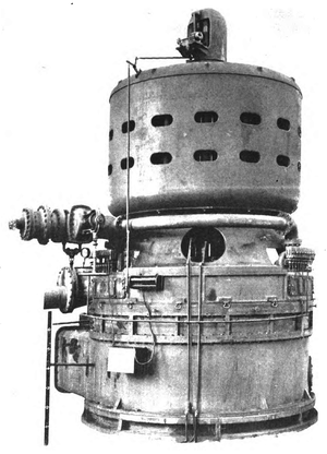 |
| Fig. 11. 5,000-Kilowatt Curtis Steam Turbine for Fisk Street Station, Chicago. |
In the "Chicago units," as they are at present being called, there are three sets of buckets on each of the two wheels corresponding to the two stages. The size and arrangement of buckets are so proportioned for the particular rotative speed that the velocity is only partly taken out in the first stage, and what remains is practically all abstracted in the second stage. So low is the velocity of steam after leaving the second stage, that the exhaust opening was made as large as possible, and the surface condenser placed almost against the side of the turbine.
The governing is done by successive closing of nozzles, provision being also made so that each nozzle can be closed gradually in regular sequence and can be worked continuously at any position between full open and closed. The governor itself is the uppermost part of the unit, being located on top of the alternator and connected to the end of the shaft.
The steam consumption of these turbines is expected to be, under full load, somewhat better than that which can be secured from the best compound, condensing engines of the same capacity tinder test conditions. On account of the turbine having practically a straight-line economy, the steam consumption under actual operating conditions should be very much better.
In exterior dimensions the turbine unit is about 26 feet high and 16-1/2 feet in diameter. It sets on a foundation about four feet above the floor, so the total height of the unit above the floor is 29 feet.
GENERAL ELECTRICAL FEATURES.
The electrical equipment of the Fisk Street station will contain several distinctive features. In the entire design the experience of European as well as American stations has been carefully considered. While each of the different generating units will ordinarily be operated independently and supply three or four feeders, provision is made so that any unit can be connected in multiple with any other, or any unit can replace any other with reference to its group of feeders.
Each turbo-alternator, with its switching apparatus and connections to outgoing feeders, forms a separate unit by itself, and is either located distinct from the adjacent units or effectually separated therefrom by fireproof partition walls. The high-tension oil switches, current and potential transformers and all connections to feeders are located in a separate building, thus eliminating all high-potential apparatus and connections from the turbine house, except the individual generator leads, which take the shortest route under the floor to the west wall, and are carefully encased.
As the arrangement of bus-bars, oil switches, etc., is necessarily influenced by space available and involves some sacrifice in the steam or electrical portion of the plant, and sometimes in both, a separate building, known as the switch house, was provided.
GENERATORS AND EXCITING SYSTEM.
The electrical generating portion of these turbo-alternators is very similar to the five generators which are being installed in Power House No. 2 of the Niagara Falls Power Company. The generators have internal revolving fields, and the provision fur ventilation is very good. Each machine has six poles and runs at 500 revolutions per minute. These alternators are guaranteed to operate at full rated load continuously, with a rise of temperature not exceeding 35 degrees C. in any part above the room temperature under normal conditions of ventilation. l he inherent regulation of the machines is eight per cent. Each turbine generator will deliver normally 5,000 kilowatts of three phase, 25-cycle current at 9,000 volts' pressure. The machines are wound with star connection and the neutral will be grounded.
An individual motor-generator exciter set consisting of a 75-horsepower induction motor mounted on the same base and shaft, with a compound-wound direct-current 125-volt dynamo of 50 kilowatts, will serve fur exciting purposes and will be located at the west wall of the turbine house opposite each turbine generator. The induction motor will be connected to a 75-kilowatt, three-phase transformer of 9,000 to 230 volts pressure, located in the switch house, so that only three-conductor No. 0000 cables of low pressure enter the turbine room. These three-conductor cables will be laid in vitrified duct.
There will be provided also two steam-driven exciters, each of 75-kilowatt capacity, with a storage battery of sufficient size.
All these different sources of supply for the excitation will be connected so that any exciter can be used to excite any one of the turbine generators. Provisions are also made to connect to the exciter bus-bars a rotary-converter sub-station of 4,000 kilowatts capacity located on the same property, so that absolute continuity of current for the exciting of the turbine generator fields is secured.
From the connection boards on the turbo-generators 500,000 circular-mil lead-covered single-conductor cables with paper insulation carry the three-phase current to the switch house.
SWITCH HOUSE
The switch house, when completed for all 14 units, will be a building about 460 feet long and 50 feet wide and will consist of a basement and two stories. The basement will contain the bus-bars, all high-tension connections and instrument transformers. On the first floor will be located the oil switches, exciter transformers and panels with supplementary indicating and recording instruments. The second floor will have a meeting room, lockers, toilet and bath and other accommodations for the turbine hence employes.
OPERATING GALLERY.
For the completed installation of 14 units there will be two operating galleries on the west wall of the turbine house, each serving for seven units. The first operating gallery will be located opposite the fourth unit. The gallery will be constructed of steel, marble and slate.
The lower story will be on the turbine-house floor and will contain office space for the chief engineer and his assistant. All turbine-house employes will pass through an adjoining room, which is at the entrance of a tunnel or passageway, running over from the switch house.
On the first floor, 14 feet above, on the same height as the main gallery, which runs around the whole turbine house, provision is made for the office of a load dispatcher, a toilet room and a small portable-instrument room.
On the floor above, and overlooking the whole turbine house, there will be one independent operating and instrument panel for each turbine generator, carrying instruments, switches, and all other necessary apparatus, as well for the generator as for the corresponding feeders or transmission lines.
In order to simplify the work of the switchboard operator as far as possible, all instruments which might be desirable for a control of the system, hut which are not absolutely necessary for a safe operation, have been removed from the operating gallery and placed in the switch house, where special care can be taken for the attendance of the recording instruments and control of the overload devices.
REMOTE CONTROL AND INSTRUMENT WIRING.
All remote-control wires consist of multiconductor lead-covered cable, arranged so that cables belonging to one unit are absolutely separated from those belonging to another unit either by vitrified ducts, fireproof walls, or slate partitions. The whole remote control wiring has been designed so that no crossings at all are required in any place; therefore all cables come over to the switch house in just the same arrangement as they leave the operating gallery. The advantage of such a lay-out with reference to repairs or inspections is evident.
TRANSMISSION LINES TO HIGH-TENSION SYSTEM.
The transmission lines or feeders to the high-tension system are so arranged that for the present there will be three lines connected through oil switches to each individual generator bus. The different generator buses can all be connected together by means of tie switches. In case of trouble, there will be two oil switches in series on generators and lines. The distribution of 9,000-volt 25-cycle lines between the different generating stations and sub-stations of the Edison and Commonwealth Companies, including the connections with the Fisk Street station, is shown in the diagram, Fig. 12.
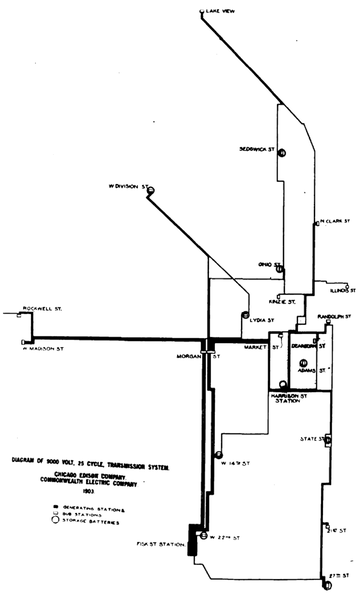 |
| Fig. 12. Alternation-Current Central Station Transmission in Chicago. |
LIGHT AND POWER FOR THE STATION.
Careful consideration led to the decision to feed the whole light and power installation for the station itself by direct current from the Twenty-second Street sub-station, located on the same property with the Fisk Street power station, and not by alternating current. This arrangement requires, of course, a certain investment in converting apparatus of somewhat lower efficiency than alternating-current transformers, but, on the other hand, direct current appeared to be much more convenient for the running of different motors, and, owing to the use of a large storage battery, it was more reliable, so that the three-wire direct-current system was adopted.
BENEFITS FOR EMPLOYES.
Ample provision has been made for the comfort and convenience of the men employed at the Fisk Street station in the way of toilet, locker and bath rooms. All of the boiler-house employes will have quarters located directly above the firing space of the north boiler-house unit. The boiler-house engineer, who will be directly in charge of this vitally important part of the plant. will have an office here, and will thus be in close communication with the men. Ample facilities in the way of shower baths, etc., will be provided.
The turbine-house employes will have their quarters on the second floor of the switch house. Here will be located their locker and bath rooms, and also an especially equipped assembly room, which can also be used as a sort of reading room for the men. Every opportunity will be taken to provide for the comfort of the men and to encourage them in reading technical literature and improving their general efficiency.
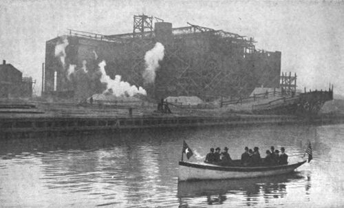
ELECTRIC LAUNCH.
After the Fisk Street property was secured and building operations were commenced, it soon be-came apparent to the officers of the company that better transit facilities than those afforded by street-railway lines would be very desirable in getting from the office building of the company on Adams Street to the property. As the site is located on the river it is easily accessible by boat, and an electric launch was therefore purchased to ply between the central part of the city and the new station. This launch, which has been named the Rotary, runs on a regular schedule from the foot of Quincy Street to the Fisk Street property and also makes stops at the Harrison and Washington Street stations of the Edison company. Department mail is carried to the stations. The launch is one of those used at the Pan-American Exposition and will seat about 20 people. It is provided with 44 Chloride cells of storage battery of 120-ampere-hour capacity and is propelled at five different speeds by a six-horsepower 88-volt motor. The launch can make four round trips a day on one charge. Fig. 13 is a view of the launch, with some of the officials of the company on board. The photograph was taken on March 9th, the day the corner-stone of the station was laid, and represents the party leaving the station.
| |||
| Fig. 13 Electric Launch Rotary in Front of Fisk Street Station. |
PERSONAL MENTION.
The general officers and the engineering department of the Commonwealth Electric Company are entitled to great credit for their acumen, self-reliance and enterprise in launching an enterprise of such magnitude as the Fisk Street station, with so many new featuresfeatures, however, which have been indicated either by the past experience of the company itself or by the latest developments of engineering design generally. Among the contributors to this great work prominent mention should be made of the company's consulting mechanical engineer, Mr. Frederick Sargent (of the firm of Sargent & Lundy), who designed the very simple plan of the turbine and boiler house as well as the arrangement of the steam and mechanical portions of the plant, which are being installed under his general supervision, while the arrangement of the electrical plant is planned and the apparatus is installed by the company's permanent engineering staff. Shepley, Rutan & Coolidge, the architects, have designed a group of buildings whose massive proportions are emblematical of a great industrial purpose, but are still not ungraceful. As the Curtis steam turbine is so conspicuous a feature of the installation, a reference to the work of W. L. R. Emmet of Schenectady, whose untiring and well considered efforts in the face of many obstacles have had so much to do with the perfecting of that interesting type of apparatus, should be made.
All the electrical equipment of this station and of the new sub-stations, as well as the steam turbines, will be furnished by the General Electric Company, with the exception of the high-tension switches, which are of the General Incandescent Arc Light Company's manufacture.
COMMONWEALTH SUB-STATIONS.
WEST TWENTY-SECOND STREET SUB-STATION.
The West Twenty-second Street sub-station of the Commonwealth company is located on the north end of the Fisk Street property, this being about Soo feet from the north end of the main generating station, as shown in Fig. 5. This sub-station was established for the distribution of direct current to the Edison three-wire system, from which is also supplied current for all lighting and general power in the Fisk Street station. This location being in the border line dividing the territory supplied by the Edison three-wire system and the 60-cycle overhead system, it was found advantageous to distribute both direct and alternating current from this point. A one-story and basement building, 50 by 65 feet in area, is being designed. The basement will contain a storage battery consisting of 150 H-41 tanks. On the first floor there will be located ultimately two 1,000-kilowatt rotary converters with accessories and switchboards and two 1,000-kilowatt frequency changing motor-generator sets with the necessary switching apparatus. Direct current will be fed into this portion of the Edison system, and there will also be some special emergency connections to the Fisk Street station so as to secure the greatest possible coefficient of reliability for a continuous supply of current for lighting and general power, which is of very great importance in connection with this particular station. Sixty-cycle alternating current at 2,400-4,150 volts will be distributed to the extended territory west and south of the sub-station.
WEST MADISON STREET SUB-STATION.
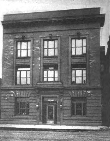
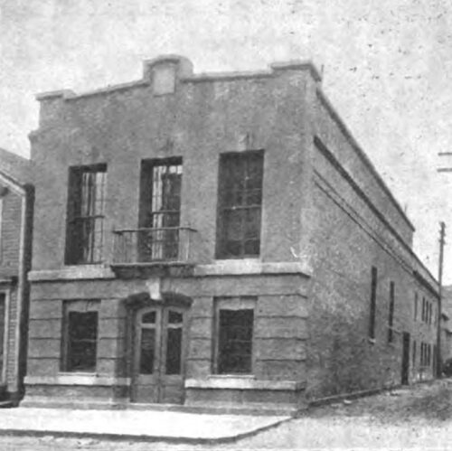
The alternating service of the Western District of the Commonwealth Electric Company is supplied from the West Madison Street sub-station. This station forms a part of a building comprising the offices of the Western District of the Commonwealth Company, the repair and sales department, and living rooms for one operator and one night trouble-man. The building, illustrated in Fig. 14, is a thoroughly modern one, being fireproof and of brick and steel construction. The front of the building, which is three stories in height, is finished in red sand-mold faced brick and terra cotta.
| |||
| Fig. 14. West Madison Street Sub- Station. |
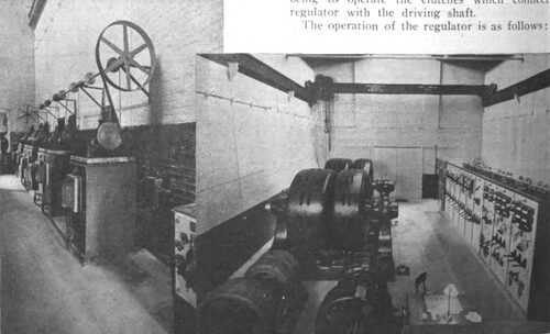
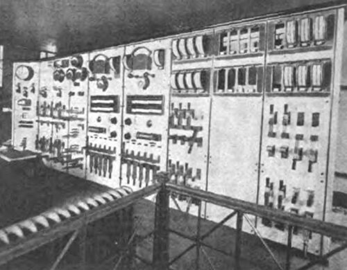
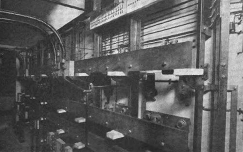
The sub-station proper contains two 500-kilowatt-frequency-changing motor-generator sets and two 50-kilowatt induction-motor exciter sets. These machines, together with the switchboards and the line switches, are on the first floor of the sub-station, as shown in Fig. 16. The basement, which extends the full length of the sub-station, contains 60-cycle and 25-cycle oil-switch buses. A 10-ton crane is also provided and so placed that all machinery can be easily handled. One of the 500-kilowatt frequency-changing sets will very soon be replaced with a 1,000-kilowatt set. The building can he extended to accommodate two more 1,000-kilowatt sets, making an ultimate capacity of 3,500 kilowatts.
| |||
| Fig. 15. Automatic Regulators. Fig. 16. General View. Interior Views of West Madison Street Sub-Station. |
The function of the motor-generators is to convert the current which is supplied as 9,000-volt, 25-cycle, three-phase energy by transmission lines about three miles in length from the Harrison Street generating station of the Edison company, and eventually from the new Fisk Street station of the Commonwealth company, to 2,300-4,000-volt, 60 cycle energy for distribution. These frequency changing sets are of the revolving-field type and each consists of two machines mounted on a common shaft with two bearings. The field of the motor has 10 poles and the field of the generator has 24 poles. The speed of these machines is 300 revolutions per minute.
Two transmission lines are brought into the stationone a No. 0000 and the other No. 00, the transmission being entirely underground from the Harrison Street station to this point. One of these lines is continued from the station, supplying the Lake Street Elevated Railway sub-station (described in the Western Electrician of May 17, 1902) a short distance away. At the point where these three lines meet, in the station, two 9,000-volt buses arc provided and all transmission-line ends are equipped with double-blade transfer knife switches, so that complete commutability is secured. The line feeding the sub-station is provided with a high-tension oil switch and is usually run on a separate bus.
All motor-generator sets are fed through three-pole double-throw oil switches installed in the basement.
The method of starting these sets is as follows: The first bus is made alive from the transmission line and the second, or starting bus, is fed from the first bus through a starting compensator which reduces the pressure from 9,000 volts to about 4,000 volts, three phase. The oil switch on the motor to be started is then thrown from the open position to the starting bus, and after the motor attains the highest speed possible on this bus it is thrown over to the 9,000-volt bus. The compensator supplying this bus is then cut out by an oil switch provided for this purpose. This method of starting has been adopted for both the larger synchronous motors of the frequency-changing sets and the smaller induction motors of the exciter sets. The double-throw oil switches which are used in this operation were built especially for this purpose, being of the double break type and provided with two sets of solenoids or operating mechanisms, one of which carries the switch from the open position to the starting, the other carrying it from the open position to the running, both being used when the transfer is made from the starting to the running. In the case of the motors of the frequency-changing sets the 9,000 volts is impressed directly on the armature but the armatures of the exciter sets are fed through three-phase transformers, which reduce the voltage from 9,000 volts to 230 volts, three-phase delta.
The method of synchronizing the motor-generators is perhaps an entirely new one, a special synchronizer being provided for this purpose. Briefly, this synchronizer consists of two parts, one of which indicates 25-cycle synchronism and the other 60 cycle synchronism. It is obvious that these machines must operate in synchronism on both the 25 and to-cycle ends and, since the numbers of pairs of poles of the revolving field of the 25 and 60-cycle machines are not the same, the 25-cycle machines or motors may be in synchronism while the 60-cycle machines would be out of phase. This relation cannot be previously determined; therefore it became necessary to adopt a scheme, which, though it savors of the cut-and-try method, is rendered exact by the synchronizer. If one motor-generator is running and it be desired to start another, the machine is brought up to speed by the method previously described, and the field of the motor is closed, thus making the motor synchronous; and then the phase relation of the two 60-cycle machines is determined by the synchronizer. If the 60-cycle machines are not in phase the motor is slipped one pair of poles or as many pair of poles as is necessary to bring the 60-cycle machines into their proper relation, a marked dial indicating the number of poles to be slipped.
The generators arc star-wound with a neutral tap brought nut and connected to the bus of the three-phase system, the 60-cycle current being at a pressure of 4,000 volts between phases and 2,300 volts between any phase and neutral. The neutral on this system is grounded solidly, and single-phase feeders from one phase to neutral and three-phase four-wire feeders distribute the energy from the buses. The single-phase feeders supply the incandescent lighting circuits anal the four-wire feeders carry a mixed load of light and power, the power load being tapped off from the three phases and the lighting load being connected between one phase to neutral. This is the well-known three-phase four-wire system that has been generally adopted by the Commonwealth company, and which was described in detail in the Western Electrician of April 12, 1902.
The oil switch used on the generators deserves special mention. It consists of three independent elements, each or all of which can be connected by means of magnetic clutches either automatically, as in the case of overload, or at the will of the operator, to a motor-driven shaft placed just before the switch. This arrangement obviates fuses and allows the machine to operate as a two-phase machine or a single-phase machine in case of a heavy overload on one phase only or on two phases of the machine, since only the element on the phase on which the overload occurs is opened by the overload.
Tic lines in the shape of four-wire feeders are brought in from two other 60-cycle stations of the Commonwealth company. All the 60-cycle feeders are provided with single-pole double-throw oil switches, and two buses are provided for the purpose of better balancing the load and for additional safety. One pole of each feeder is connected directly to the neutral bus without the intervention of fuses or switches of any kind. All instruments on these feeders arc taken from the secondaries of pressure and current transformers provided for the purpose. The four-wire three-phase feeders are each provided with three spring-expulsion fuses and lightning arresters, as the 60-cycle distribution is an overhead system. The single-phase feeders arc each similarly provided with one fuse block and lightning arresters and have in addition pressure compensators and automatic potential regulators. These regulators, shown in Fig. 15. have a capacity of 7-1/2 kilowatts each and are very interesting mechanisms. They consist primarily of the regulator proper, which is really an auto-transformer with adjustable secondary, coils being cut in and out by a movable knife blade on a dial. The power to move this blade is furnished by a shaft driven by a motor. The other essential part of the regulator is a relay, which operates as the pressure rises and falls from a predetermined point, the function of this relay being to operate the clutches which connect the regulator with the driving shaft.
The operation of the regulator is as follows: The pressure compensators, arranged for ohmic and inductive drop, are so set as to give a reading on the feeder voltmeters which is equal to the pressure at the center of distribution, thus obviating pressure wires. A standard voltage having been predetermined, it is necessary to maintain this voltage, and any departure therefrom is taken account of by the relay, which is connected in multiple with the voltmeter. The variation of pressure causes the relay to energize a direct or reverse clutch, which connects the dial switch with the driving shaft. The knife blade on this dial switch is then carried around the dial, cutting in or cutting out coils of the secondary of the auto-transformer, thus raising or lowering the pressure according to the direction of its travel.
This sub-station has been in operation for about six months, and while a great deal of this apparatus was gotten out on development orders, the purpose of the apparatus seems to have been admirably fu filled and no serious difficulties have been encountered, notwithstanding anticipated possibilities of trouble.
Induction-motor sets were chosen for exciting purposes because it was thought that in case of transmission-line disturbances the effect on the source producing exciting current would be a minimum, since these machines do not follow up the line fluctuations as closely as do synchronous motors and this idea has been fully home out by the experiences of the past year of operation.
LAKE VIEW SUB-STATION.
The Lake View plant of the Commonwealth Electric Company is located about four miles north and one mile west of the Harrison Street station. This plant was originally a two-phase moo-volt alternating station with a total load of about 150 kilowatts of series arcs and 50 kilowatts of 500-volt power, and supplied the territory north of the northern limits of the Edison direct-current service,
Two years ago the first motor-generator set was installed and the service changed over to 60-cycle four-wire, three-phase. The same standard was adopted as that in the Southern and Western Districts of the same company and described elsewhere.
The series arc and 500-volt power machines were belted to the motor of this motor-generator set and the pressure from the two-phase machines raised to 2,000 volts by means of transformers on the lighting circuits. These old machines then supplied the single-phase feeders in part and were left in service until a 500-kilowatt motor-generator set and a 500-kilowatt 60-cycle belted generator, readily convertible to a motor-generator set by replacing the engine pulley with a motor, displaced them. The series arc and 500-volt power service is still maintained but is on the decrease, as all efforts are directed toward developing the three-phase power. The series arcs are gradually being displaced by low-tension alternating arcs.
The present equipment, therefore, consists of one 250-kilowatt, 9,000-4,000-volt, 25-60, four-wire, three-phase motor-generator set, one boo-kilowatt set, and one 500-kilowatt belted generator identical with the generator of the larger motor-generator set, and miscellaneous series arc and 500-volt power machines. The 500-kilowatt belted machine was installed for the purpose of utilizing a 600-horsepower cross-compound engine as peak capacity.
The auxiliary apparatus is the same as that used in the West Madison Street sub-station, except that belted exciter sets are used at present. These, however, will be displaced by induction-motor-driven sets in the near future. The methods employed in starting up and synchronizing are also the same.
Two transmission lines, equipped with oil switches, one No. 0000 and one No. 00, feeding into the sectional 9,000-volt bus, supply this sub-station with 25-cycle current from the transmission lines running from the Harrison Street station via intermediate sub-stations, and a great flexibility in the transmission system is thus secured.
It will be seen, therefore, that although the old site and building have been retained, there has been a complete transformation in the service supplied to customers, and a great increase in business has accompanied this transformation.
EDISON SUB-STATIONS.
WEST DIVISION STREET SUB-STATION.
In the northwestern part of the Chicago Edison Company's territory and very close to the Western District of the Commonwealth company, which is all supplied by standard 60-cycle, four-wire, three phase system, the West Division Street sub-station was erected about nine months ago. This is a modern brick and steel fireproof building about 47 by 65 feet in size with two stories and basement.
The basement extends under the entire building and contains a storage battery of 150 G-49 cells with the necessary end-cell switches. A portion of the basement contains the 60-cycle bus fed by the motor-generator and the rest is devoted to cable runs and miscellaneous purposes.
On the main floor of the sub-station there are, at present, one boo-kilowatt motor-generator set, one 500-kilowatt rotary-converter outfit and one 500-ampere three-unit booster set for charging, with their respective alternating-current operating board and direct-current board.
Above the first floor in the front part of the sub-station is the high-tension gallery which contains the high-tension buses and line switches of the transmission lines. The floor above is divided into two living apartments for one operator and one trouble-man of the district.
Two transmission lines, equipped with oil switches, supply the 25-cycle 9,000-volt energy to sectional buses, which may be tied together. These lines run from the Harrison Street station via other Edison sub-stations.
The motor-generator equipment is identical with that of the other two motor-generator installations. The rotary converter with its appurtenances is installed and provided as those in other Edison substations. Three single-phase transformers, delta-connected, are used on the present installation but a three-phase transformer will be substituted in the next outfit.
A compensator, which is really a Y-connected inductive resistance, furnishes a neutral for the rotary converter. On account of the mixed character of the load on the sub-station and 60-cycle tie lines, considerable flexibility is secured. For instance, a feed could be taken from the 60-cycle tie line which would operate the motor-generators conversely and furnish 9,000-volt, 25-cycle energy to the 9,000-volt bus of the sub-station, which could operate the rotary converters. Or the battery could supply direct current to the rotary converters which, running conversely, would operate the motor-generators.
This sub-station was installed with the idea of relieving other sub-stations of load, this fact accounting for the initial capacity necessary.
SEDGWICK STREET SUB-STATION.
The sub-station of the Chicago Edison Company at 444 Sedgwick Street, near North Avenue, known as the Sedgwick Street sub-station and illustrated in Fig. 17, is one of the smaller installations on the 25-cycle system, but it contains several distinctive features of design and is an example of what can be done on a narrow lot in a locality where real-estate values are moderate.
| |||
| Fig. 17. Sedgwick Street Sub-Station. |
The equipment consists at present of one 500-kilowatt rotary-converter outfit, a 350-kilowatt battery at one-hour-rate of discharge (G-49 tanks) and a 500-ampere three-unit booster set. Two additional rotaries of 1,000 kilowatts each can be accommodated in the present building. Front and rear views of the switchboard are given in Figs. 18 and 19.
| |||
| Fig. 18. Switchboard |
| |||
| Fig. 19. Rear of Switchboard. |
| |||
| Fig. 20. Automatic High-Tension Oil Switches. Views in Sedgwick Street Sub-Station of Chicago Edison Company. |
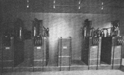
The battery occupies the two-story section of the building at the rear of the lot and is arranged with positive cells on the second floor and negative cells on the first floor. A fire wall with one connecting door separates this section from the rotary-converter section.
The following are briefly the principal features of the sub-station:
FirstAll heavy apparatus is on the main floor and is accessible from one crane.
SecondAir-blast equipment in basement, hence no platforms required for transformers and regulators.
ThirdBasement space for rheostats, cabling and heating plant is provided, thereby relieving the substation space.
Fourth--High-tension switches and buses isolated upon the gallery.
FifthBuses in separate brick compartments located under switch terminals; divided in sections, one line and one rotary on each section.
SixthOil switches (Fig. 20) have auxiliary knife-switch contacts to cut out oil wells for inspection and cleaning; also oak and plate-glass doors, front and back, to facilitate inspection.
SeventhFrom transformer secondary to rotary there are no fuses or switches.
LYDIA STREET SUB-STATION.
At the Lydia Street sub-station of the Chicago Edison Company it was necessary to provide service for a number of large customers before it was possible to build and equip a permanent sub-station. Hence a temporary building large enough to accommodate two 500-kilowatt rotaries was erected on the rear of the lot at 144 West Lake Street and one rotary was put in service on May 1, 1902, just 30 days from the time the wreckers began to demolish the old building. Footings, foundations and basement steel work were then put in for a six-story building, on the front portion of the lot, and a basement battery room was finished up with a 1,200-kilowatt battery to take the fall peak. Only a one-story building, providing room for 2,500 kilowatts in rotary converters, is being put up on the front portion of the lot, as shown in cross-section in Fig. 21.
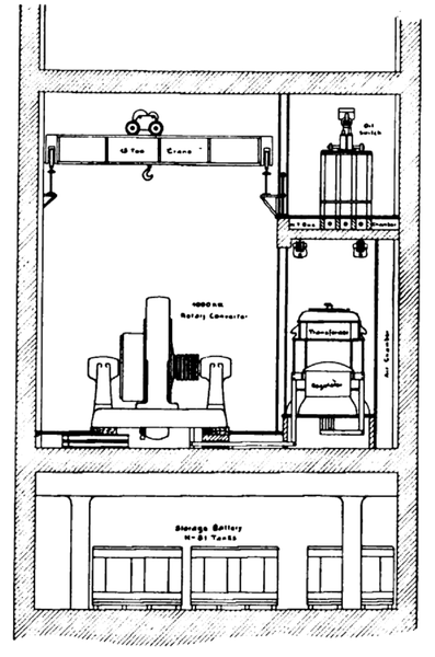 |
| Fig. 21. Sectional Drawing of Lydia Steeet Sub-Station. |
The ultimate equipment of this sub-station contemplates the following principal distinctive features:
FirstA six-story building with battery and heating plant in basement. The first floor and gallery floor to be occupied by the sub-station proper. The remaining floors can be used for storage or rental for manufacturing purposes.
SecondA 9,000-volt line feeding to sectional buses; each section feeding one rotary; sections tied into continuous bus by switches, all switches used being brick-compartment oil switches.
ThirdThree-phase transformers of 9,000-kilo-watt capacity used with 88-kilowatt induction regulators and 1,000-kilowatt rotary converters.
On all rotary-converter installations for the current year the company has adopted the use of one three-phase transformer, instead of three single-phase transformers for each rotary converter, the line current being brought in at 9,000 volts, 25-cycle, three-phase, and the secondaries being six-phase diametrically connected. The design of the transformer is such that it consists essentially of three single-phase transformers effectively isolated from each other, but mounted in a single iron case in a very compact manner. So effective is this isolation that it would be possible to continue a transformer in operation even after one section had been damaged by accident. All the advantages of the three single-phase transformers are thus secured, and the additional advantage of a great saving in weight and floor space is obtained. A connection is made to the common point of the diametrically connected secondary, which connection is taken direct to the neutral of the system. Each 250-volt rotary converter thus equipped is treated, as far as instruments and switches go, the same as two 125-volt machines.
FourthUltimate capacity of five units, or 5,000 kilowatts.
FifthDesigned to accommodate two direct-current switchboards, one at each end, if necessary.
SixthOn account of basement battery room, space on the sub-station floor for machine pits and cables is provided by a false floor of slate supported upon brick walls, which also serve to isolate cable work.
SeventhBlower equipment in duplicate for transformers and regulators, with additional capacity and devices for supplying air to rotaries under overload conditions.
EighthThree-unit booster outfit of 2,000-ampere capacity; also arranged so that it can be used as balancer. Each of the boosters used for charging storage batteries is also equipped with some. special switches so that two 70-volt boosters can be operated in series and connected to the side of the three-wire system that may have low-pressure, due to heavy unbalance.
NinthRheostats motor-controlled and mounted on gallery away from switchboard.
TenthFive-thousand-ampere circuit-breakers with reverse-current attachments on both direct-current leads of rotaries.
MARKET STREET SUB-STATION.
The Market Street sub-station of the Chicago Edison Company, located at 84-86 Market Street, is designed to enable the shutting down eventually of the Washington Street generating station, now known as station No. 5, during the greater part of the year. The present building is only a small part of the very extensive block which will ultimately be erected on the property at the corner of Market and Washington Streets.
The principal features of this installation are as follows:
FirstAn eight-story modern steel building, supported upon concrete caissons, extending to bedrock, a distance of approximately 90 feet.
SecondThe ultimate sub-station will occupy three bays on the main floor of the present building and will consist of eight 1,000-kilowatt rotary converters in two rows of four each, with a 20-ton crane in each of the three bays.
ThirdThe first installation will consist of tour 1,000-kilowatt rotaries, with three-phase transformers, occupying about one hay and a half, the remaining space to be utilized for storage purposes for the present, or until needed for rotary converters.
FourthIn this station the high-tension buses will be located in an air chamber in the basement. The scheme of sectional buses, with brick-compartment oil switches, will be followed throughout. The rotary switch, however, will be located on the main floor, near the high-tension side of the transformer.
FifthThe layout is such that, in case it is desirable, two 2,000-kilowatt machines can be installed in the same space as three 1,000-kilowatt machines, thereby increasing the ultimate capacity of the station 33-1/3 per cent. All the heavy apparatus in this station is easily accessible from the cranes.
SixthThe direct-current switchboard will be protected from above by a gallery which will accommodate the starting resistances and motor-controlled rheostats.
SeventhThe battery room and end-cell switch room will occupy the floor immediately above the sub-station.
EighthTransformers and regulators of such capacity wilt he used so that the battery may be charged direct, thus avoiding the use of a booster, the principal object of this arrangement being to save valuable floor space.
MORGAN STREET SUR-STATION.
This sub-station is located on Morgan Street. between Monroe and Adams Streets, It is a two-story and basement building, and will, when extended ultimately, contain five 1,000-kilowatt rotary converters on the first floor and a storage battery consisting of 150 H-33 tanks, on the second floor. The basement will be used for air chambers, bus-bar and cable connections, heating plant, etc. A portion of the present building will also be used, temporarily, as a central distribution for the 9,000-volt transmission system. Lines will be amply protected and isolated in fireproof compartments. 1 ne establishment of this temporary center means a very great reduction in the cost of transmission line capacity between this point and the Fisk Street station, particularly during the development period of the latter. Ample room on the property is provided for extension.
OHIO STREET SUB-STATION.
This sub-station is located on the north side of Ohio Street, about 215 feet west of Orleans Street. It will consist ultimately of five 1,000-kilowatt rotary converters, with all accessories and switchboards, located on the first floor, and a storage battery of 150 H-49 tanks on the second floor. The basement is reserved for air chambers, bus-bar and cable connections heating plant, etc.
The ultimate floor plan of this sub-station will be 50 by 100 feet in size, only a part of which is being put up at present. The width of the lot is such that a very safe and economical arrangement of machinery was possible, and, when completed, it is expected this will be one of the model sub-stations of its kind in Chicago. The basement allows ample room for the safest cabling, and there will be absolutely no high-tension connections inside of the rotary room, as the connections to the oil switches are all made at the bottom.
A booster will be used for charging the storage battery and will be so arranged that the two generators can be kept in series on the low side of the Edison three-wire system, and the booster set will be used as a balancer set.
The low-tension switchboards on all rotary-converter sub-stations of the Chicago Edison Company for this year will be of the company's standard design, which is very similar to that used in the Randolph Street sub-station, described in detail in the Western Electrician of November 29, 1902.
There are also a number of minor improvement, in the company's sub-station design, one of these being two direct-current meters and circuit-breakers installed on each rotary, instead of one, as the connection of the neutral point of the three-phase transformer to the neutral of the Edison system makes this necessary.
CONCLUSION.
Mention has now been made of the more important work that has just been completed or is now in progress for some of the generating and sub-stations of the Chicago Edison and Commonwealth Companies. In all there are 25 such stations and sub-stations, as shown by the general map (Fig. 4. In the stations and sub-stations not specifically mentioned improvements and construction work of more or less importance are also in progress, planned with the view of taking care of the rapidly increasing load and keeping the system up to the highest standard of central-station practice.
During the last year the Edison company has installed new storage batteries as follows: Harrison Street, 160 H-61 elements; Lydia Street, 150 H-81 elements: West Division Street, 150 G-49 elements; State Street, 150 G-33 elements, besides increasing the number of plates to full capacity of the tanks in the Sedgwick and West Fourteenth Street substations.
The two companies are at present installing five L000-kilowatt rotary-converter outfits, 12 500-kilowatt rotary-converter outfits, two 1,000-kilowatt and two 500-kilowatt motor-generator frequency-changing equipments, 12 auto-potential regulators. besides a large quantity of miscellaneous switching and regulating apparatus, involving six new sub-station buildings for this year. This is in addition to the generating equipment installed or being installed in the Harrison and Fisk Street stations, and previously mentioned.
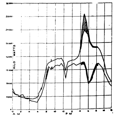 |
| Fig. 22. Typical Winter and Summer Load Curves of Chicago Edison and Commonwealth Companies. |
The Edison and Commonwealth companies together furnish current at present to a total connected 16-candlepower-lamp load of 1,651,700 lamps, divided as follows: Edison, 1,155.200; Commonwealth, 496,500. The total maximum output of the companies to date is 20,000 kilowatts, distributed as direct current 24,000 kilowatts, and as alternating current 5.000 kilowatts. In Fig. 22 is shown a combined load diagram of the two companies, indicating the total generated output for typical winter and summer loads. Curve I. is a curve of the load on December 22, 1902, and curve II. shows the generated load on as recent a date as May 8, 1903. In both curves the storage-battery discharge on the peaks is indicated by the shaded portions.
The present rate of increase gives promise of being equally as good as, if not better than, the phenomenal increase of the last two years. This rapid growth has severely taxed the engineering department of the companies to provide and install the necessary apparatus and likewise the operating department to handle the load.
