[Trade Journal]
Publication: Western Electrician
Chicago, IL, United States
vol. 19, no. 22, p. 264, col. 1-3
Distribution of Niagara Power at
Buffalo.
BY ORRIN E. DUNLAP.
The city of Niagara Falls is again talking of a power celebration, to be held some time next summer. There is also some talk of having the two power companies light the streets connecting the two power districts with a double row of lights, so that a grand display of Niagara's electrical energy may thus be made. The successful inauguration of the transmission project to Buffalo, described in the last issue of the WESTERN ELECTRICIAN, has increased the interest and enthusiasm of the people of Niagara Falls, if that were possible. Enough has already been said about this event, but some account of the commercial negotiations leading up to it may not be uninteresting.
The Niagara Falls Power company's contract with the Buffalo Street Railway company calls for the delivery of 1,000 horse power at $36 per horse power. This power will be taken from the copper bus-bars into which the big generators deliver their product in the power house. In connection with this installation it may be stated that the General Electric company entered into three separate contracts, and therefore three separate companies are interested in the apparatus installed. The first contract was made with the Cataract Construction company. This contract was for three air-blast transformers, blower motor and switchboards. Each of these transformers is of 1,250 horse power capacity, and any two of them can be used to transform 2,500 horse power delivered to them in two-phase currents at 2,200 volts to three-phase currents at either 11,000 or 22,000 volts. In these transformers the coil connections are so arranged that the change in the voltage from 11,000 to 22,000 can be easily effected. Both the primary and secondary connections of this power of transformers lead to a switchboard. The low-tension board is fitted with switches and fuses, while the high-tension board is fitted with switches, fuses and current indicators. Under the contract with the Cataract Construction company the General Electric company has installed the transformers with all cables, connections, etc., from the generators in the power house to the transmission line. Lightning arresters have been placed in a small building on the south side of the transformer house at the point where the cables leave the building. The third transformer furnished under this contract is held in reserve. The design adopted for the Niagara installation is such that it can be extended until the full capacity of the transformer house is reached. The transformers are unassuming machines. The two now in place stand at the eastern end of the transformer room and are supported on an iron framework, their bases being eight feet below the floor of the transformer house. The space below them is practically an air-tight enclosure through which all connections to the transformers are made. In the pit below the transformers there is ample room for
| |||
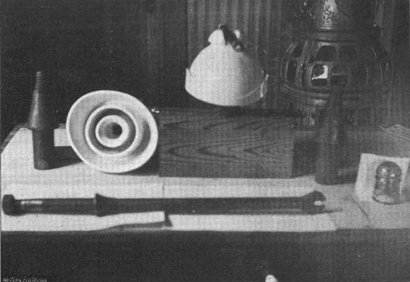
| Fig. 1 Distribution of Niagara Power at Buffalo the Niagara Type of Insulator, the Pins, A Section of Double Cross-Arm, and the Pin Used to Support the Lightning Protector Wire on the Arms. |
walking about, all conductors and connections being supported on large porcelain insulators and iron brackets. The connections to the transformers are made so that they can be detached without much trouble, and at any time when it is found advisable to substitute the extra transformer for one of those now in service these connections will be opened and the transformers changed with the aid of a crane. In the southeast corner of the transformer room stands a large centrifugal blower, which is driven by a five horse power electric motor which stands close beside it. This blower delivers air to the enclosure below the transformers, from which point the air passes upward through spaces provided between the coils, and also by a separate space provided between the laminations of the iron. The amount of air delivered in each of these places is controllable by valves so that the temperature can be suitably adjusted with the minimum load on the blower motor. The arrangement of coils in these transformers is such that very strong insulation will have to be punctured before connection can be made between the different coils, or between the coils and the iron. At the same time the air spaces are so placed that the air is brought intimately in contact with each coil and gives an excellent cooling effect. This method of cooling makes necessary the occupation of a good deal of space in insulation and air, which has a tendency to increase the size of each transformer. Still, it is very apparent that it has the very great advantage of making the transformer clean and accessible, and much more convenient to handle than a transformer cooled by another method.
The second contract the General Electric company entered into in connection with the Niagara-Buffalo transmission was with the Cataract Power & Conduit company of Buffalo. This company was incorporated July 17, 1896, with George Urban, Jr., as president, and it will be the distributing agent of Niagara power in the city of Buffalo. Among others interested in this company are William B. Rankine, D. Ogden Mills, John Jacob Astor, Edwin D. Adams, Francis Lynde Stetson, E. A. Wickes and Daniel O'Day. The company's contract with the General Electric company called for four 360 horse power transformers to be used in reducing the current from the line to a voltage suitable for connection to 500 volt rotary converters. These transformers are installed in a special building connected with the Buffalo Street Railway company's power house. Their general construction and the method of cooling employed is very similar to that used with the large transformers at the Niagara Falls end of the line. This building is also provided with switchboard and lightning arresters.
| |||
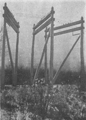
| Fig. 2 Distribution of Niagara Power at Buffalo the Completed Corner Construction. |
It was with the Buffalo Street Railway company that the third contract was made, and for it the General Electric company furnished and installed two 500 horse power rotary converters, with switchboard and instruments etc. These rotaries will supply current to the lines of the Buffalo Street Railway company, or in parallel with the generators now in their power house. The rotaries have six poles, and operate at a speed of 500 revolutions per minute. They can be started either from the alternating current or by direct current from the lines to which they are attached.
It is significant of the enterprise of the Niagara Falls Power company that they have built this transmission line and transmitted Niagara's force to Buffalo at this early date, when their Buffalo franchise simply demands that they shall be prepared to sell current in that city on June 1, 1897. The erection of the line in the short period that has elapsed since it was started is most creditable to all who had contracts. Especially is this true of the work of the White-Crosby company and the General Electric company.
At present three styles of insulators are on the line. The most noticeable of these, however, is the Niagara type, made by the Imperial Porcelain Works of Trenton, N. J. The poles used in the construction of the line were furnished by Thomas Barnard of Lockport, whose men cut about 1,500 of them on the Indian Peninsula, Georgian bay, while about 1,300 of them were obtained at various points along the Canadian Pacific railway.
| |||
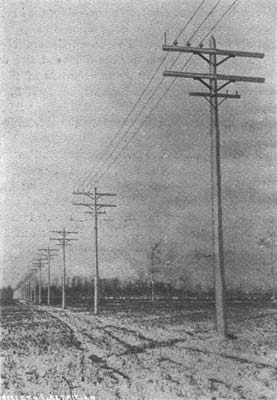
| Fig. 3 Distribution of Niagara Power at Buffalo the Pole Line. |
The first power sent to Buffalo was at a voltage of 11,000, and now that the line is in successful operation, it is probable that the news will soon come that Buffalo is prepared to use more power. The Buffalo franchise calls for the delivery of 10,000 horse power thereby June 1st next, should there be a demand for it, and also that the power company, if there be a demand, shall be prepared to supply 10,000 additional horse power within each successive year thereafter for four years. This would be a total of 40,000 horse power, or the total product of eight generators.
In preparation for an increased demand for power the Niagara Falls Power company has decided to install five new turbines and generators in the wheelpit and power house extensions as soon as they are ready for them.
At a recent meeting the company received applications from tenants already on its lands for 5,000 additional horse power, which is evidence that several of the firms now doing business there intend to enlarge their facilities.
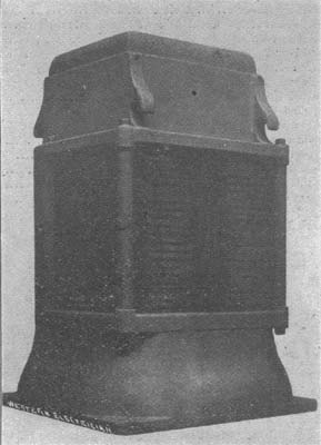
| |||
| Fig. 4 Distribution of Niagara Power at Buffalo Transformer. |