[Trade Journal]
Publication: American Electrician
New York, NY, United States
vol. 8, no. 8, p. 268-270, col. 3,1-3
THE NIAGARA-BUFFALO ELECTRICAL
TRANSMISSION.
The Niagara-Buffalo transmission was inaugurated on Nov. 16, one minute after midnight with unqualified success, and electrical power from Niagara is now used to propel the electric cars of a number of important lines in Buffalo, the amount used being 1000 HP.
The transmission line is 26 miles long and passes over a private way. It is carried on shaved cedar poles painted white, ranging in height from 35 to 60 ft., according to the locality, and from 60 to 75 ft. apart. The poles are set 6 to 8 ft. deep, some simply placed in the clayey ground and tamped, while others, in moist, and soft earth, are set in concrete. The pole line was erected by the White-Crosby Company.
 |
| Fig. 1 Section of Porcelain Insulator. |
Each single pole carries three cross arms, the upper two for the transmission wires, and the lowest for a telephone circuit. The transmission cross arms are of yellow pine, 12 ft. long X 4 3/4 ins. X 5 3/4 ins. Each arm will carry six insulators, three on each side of the pole, but three only are now in place screwed to wooden pins. On the outer end of each upper arm are two 18-in. iron pins on which is strung a galvanized barbed iron wire, which, grounded every fifth pole, serves as a lightning arrester.
The line consists of three conductors of bare copper, of 350,000 cm. cross-section, each conductor being a nineteen-strand cable. Complete transposition of the wires is effected every five miles. These conductors are strung on porcelain insulators of heavy pattern, made by the Imperial Porcelain Works, Trenton, N. J. These insulators, one of which is illustrated in Fig. 1, have the appearance of large inverted soup bowls, with a cap having a longitudinal groove and two wings and a special drip-way on the upper surface. Beneath they have two deep annular grooves, to prevent any moisture connecting the outside of the insulator and the supporting pin and thus cause a ground. Each insulator weighs about 12 lbs., and before acceptance was subjected to a test of 40,000 volts alternating. Failure in the smallest degree insured rejection. The conductors lie in the longitudinal grooves and are tied to the wings.
The total length of the line is 26 miles, and as the three-phased system demands the use of three circuits, the total length of conductor is 78 miles, the cable for each mile weighing about 5200 lbs. With a transmission of 1000 HP at 10,000 volts, the total drop is less than 3 per cent., the line being designed for 5000 HP.
The last 4200 ft. of the line is underground through a subway consisting of twelve ducts of vitrified tile laid in four layers of three each, each duct having a diameter of 3 ins. in the clear. The twelve ducts are surrounded on all sides with 4 ins. of concrete as a protection, and the top of the concrete is 18 ins. below the surface. This conduit is laid along the canal bank, and has sixteen manholes.
The overhead line from Niagara dips to a terminal house and is connected through lightning arresters to the underground cable, which runs along a short tunnel connecting the terminal house with the first manhole of the conduit.
The underground cable was supplied by the Safety Insulated Wire Company, and is insulated with 9/32 in. thickness of rubber, then braided and sheathed with a heavy lead armor. This cable was tested to 40,000 volts for acceptance, and to 30,000 volts for experiment. It is said to have withstood the latter test without revealing weakness in the insulation. The conduit continues as far as the transformer house a small one- roomed brick structure, built in the rear of the Niagara Street power house of the Buffalo City Railway Company.
| |||
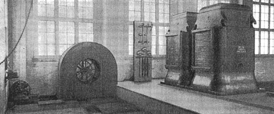
| Fig. 2 Step-Down Transformer Station Buffalo. |
The two-phased currents from the great 5000-Hp generators revolving in the power house at Niagara, passes at a voltage of 2200 to the main switchboard. That portion intended for Buffalo is led in lead-covered cables over the bridge across the canal, where the cables are connected to the two-phased low-potential switchboard. From this they descend into an air-tight chamber in which are built the transformer supports.
In this room, large enough for a man to move about in comfortably, all connections between the low-tension two-phased lines and the step-up transformer wires are made, the cables being supported by large porcelain insulators on iron brackets.
| |||
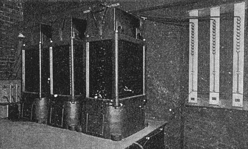
| Fig. 3 Step-Up Transformer Station Niagara. |
The "step-up" transformers now in position (Fig. 3) number two, and are rated at 936 KW each. They represent the latest practice in transformer design, are the largest yet constructed, and of the air blast type. Into the air-tight chamber beneath the transformers air is forced by a 60-in. blower, driven by a 5-HP multipolar direct-current motor. The coils of the transformers are arranged with the major axes in a vertical plane, and two main passages are provided one through the iron of the core, and the other through the spaces between the coils. Through the open cast iron pedestals on which the transformers stand a blast of cool air passes directly into the main air passages and thence into a number of minor air ducts in the transformer. The admission of the air is regulated by dampers, which may be adjusted independently either for the coils or the core.
The step-up transformers are 94 ins. high, and each weighs 25,000 lbs. They raise the voltage from 2200 volts to 11,000 at present, but are designed to allow of a voltage of 22,000 by a change in the connections. They stand on frustrums of rectangular pyramids mounted on an iron framework and are encased in suitable iron frames, the frame being provided on the top with cast lugs by which they may be readily handled with the traveling crane which runs along the roof of the transformer house.
It is in these transformers that the two-phased system is abandoned. From them three currents issue differing in phase by 120 degs. The connections are brought out at the bottom, and continue to the high tension marble switchboard for connection to the transmission lines. The equipment of this board is of special design to permit of the handling of the high voltage current without danger. Each conductor from the transformer is connected to a single-pole switch of quick-break type, mounted on heavy insulating pedestals, and separated from its neighbor by a barrier of marble much higher than the closed switch and about one inch thick. These three switches control the output of any two of the 935-KW step-up transformers which may be connected for either 11,000 or 22,000 volts. Each conductor has its fuse carrier of special type designed for this transmission. Each carrier is twenty-four inches long and is forced into contacts mounted, like the switches, on large insulating pedestals. Each has two handles, and the construction is such that they can be removed from the board for the insertion of new fuses without danger. The high tension switchboard also carries current indicators and voltmeters. From this switchboard the conductors pass to a small extension building where they are connected through lightning arresters to the overhead wires leading to Buffalo.
The transformation of the current at the Buffalo end of the line is effected in three "step-down" transformers (Fig. 2), constructed similarly to those used to step-up the pressure, and cooled by the same process, the centrifugal blower being driven by a 2-HP motor. The line enters the small building outside the railway company's power house, from the underground conduit, through lightning arresters and is connected to the high tension switchboard, which is a duplicate of that in the transformer house at Niagara. From the switchboard the conductors are brought into the transformers from the top, and the three currents issue at about 370 volts pressure.
Three of the four step-down transformers are set up. Each is 32 ins. high and weighs 7000 lbs. The currents are turned into them at 10,700 volts or 21,400 volts pressure, and issue at the pressure just mentioned.
| |||
| Fig. 4 Direct Current Transformers at Buffalo Station. |
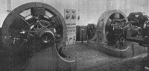
From the transformers six cables that is, three for each three-phased circuit are carried through the wall of the step-down transformer house up to the main floor of the railway power station above. Here they are connected to the switchboard equipped with six knife-blade switches, one for each cable, ammeters, etc. a field switch and two switches connecting to the main bus bars of the railway switchboard. From the board the two three-phased circuits run to two rotary converters (Fig. 4), each of 500 HP capacity. These converters are six-pole machines and by their operation the three-phased, 370-volt alternating currents are changed into a direct or continuous current at a voltage of 500 for connection to the feeder lines of the railway company. The armature of the converter is fitted with three alternator collector rings on the side nearest the switchboard, while the other carries a commutator similar to that of the ordinary direct-current dynamo. The three-phased currents are brought to the brushes and enter the armature. As soon as the necessary speed is reached, as indicated by the voltmeter, the main switch on the board is closed and the direct current passes from the commutator brushes to the main buses of the railway switchboard. The converters may also be started by direct current taken from the lines, and the direct current from them can be thrown either to the board for operation in parallel with the generators now in operation in the power house, or directly to the feeders.
The lightning arresters of the Wurts type have been especially designed for heavy voltage transmission work and are single-pole. They consist of a strip of marble upon which are mounted eleven cylinders, giving one air gap space 1/32 in. for each 1000 volts, with an allowance of 25 per cent. rise in the potential. In the action of the arrester the large metal cylinders serve to chill the arc, so that on reversal of the current the arc is extinguished, no dependence being placed upon any non-arcing property of the metal to put out the arc. In order to limit the current on short circuit, and thus the heating effect, a special solid graphite rod of low non-inductive resistance is used. The arresters are similar to those used on the Big Cottonwood transmission at Salt Lake City, which have effectually protected the machinery in many severe storms, and are now being used extensively in transmissions where high voltages are employed.
The carrying capacity of the present three-phased circuits at 11,000 volts, is 5000 HP; at 22,000 volts, with a smaller drop, 10,000 HP. The capacity of the pole line, therefore, is 40,000 HP at the higher voltage.
At Niagara Falls an extension of the power house equipment is already under way. The output of the present 5000 HP generators, three of which are in constant operation, is already taken and distributed to the factories of the Carborundum Company, the Calcium Carbide Company, the Niagara Falls Paper Company, the Pittsburgh Reduction Company, the Niagara Falls Chemical Company, to the Niagara Falls & Buffalo Railway, a line of electric cars running between the two cities, and other lines in Niagara. Another wheel pit, of similar depth to that already in use, is being excavated as a continuation. It will be three times as long, or 430 ft. X 20 ft. and will contain, when equipped, seven additional turbines with penstocks and turbine shafts. Seven additional 5000-HP generators will be operated by these turbines, and the complete plant will have a total output at full load of 50,000 HP.
