[Trade Journal]
Publication: The Telegrapher
New York, NY, United States
vol. 8, no. 6, p. 41-42, col. 1-3
Original Articles.
Notes on the Glass Insulator.
BY F. L. POPE.
THE first telegraphic insulator used in America was composed of cloth, saturated with gum lac, and wound around the line wire at the point of contact with the supports. This was on Morse's experimental line between Baltimore and Washington, in 1844. It was very soon discovered that this plan would not answer. Various other methods of insulating the wires were suggested, but finally it was determined upon to employ glass - a substance that combined the requisite mechanical strength with the most perfect non-conducting qualities, and, moreover, was not liable to decay from exposure to atmospheric influences. From that day to this the glass insulator, in one form or another, has been one of the recognized "institutions" of American Telegraphy.
The first glass insulator was a simple knob, like a bureau handle, mounted upon a wooden pin. Experience soon showed that although the glass itself was, for all practical purposes, a perfect non-conductor, yet the moisture which accumulated upon the surface of each insulator in damp weather, and especially during rain, formed a continuous conductor for the escape of the electric current from the wire to the support, and the aggregate of these leakages was often more than equal to the conducting capacity of the wire itself.
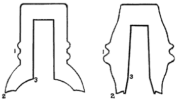
Some inventive genius, whose name the writer has unfortunately not been able to ascertain, undertook to form the glass so that its lower portion should form an overhanging drip or shed, and thus break the continuity of the line of watery connection between the wire and the support. This was the origin of the well known "umbrella" insulator, which, after one or two experiments, finally assumed the form shown in Fig. 1, which it has substantially retained to the present day.
 |
| Fig. 1 Fig. 2 |
The employment of the overhang or drip, though it sensibly diminished the evil it was intended to counteract, did not by any means entirely prevent it. In long continued rains, when the atmosphere becomes saturated with moisture, and especially when a rise in temperature causes this moisture to be condensed upon the glass, the surface underneath the drip soon becomes covered, in common with every other portion of the insulator, with an unbroken and continuous film of water, which is attended with a corresponding escape of electricity. This fact has always constituted the chief objection to the employment of glass as an insulator, as it has been found practically impossible to prevent this deposit of moisture upon its surface under certain atmospheric conditions.
In order to form a correct conception of the part actually played by the glass insulator under the atmospheric conditions above referred to, it is necessary to consider the insulator - or rather the film of water upon its surface - as a conductor; its value, in this connection, depending upon its resistance to conduction. Following the ordinary law of conductors, the greater the length of surface between the wire and supporting pin, and the smaller the diameter of the insulator, and consequently the breadth of the conducting film upon the surface, the greater will be its resistance and the better the insulation. A moment's reflection will convince any one of the correctness of this theory, which has been abundantly verified by experiment.
The form of insulator shown in Fig. 1, viewed in this light, can hardly be regarded as a success. The length of surface from the point where the line wire is attached, at 1, to the point of drip at 2, and thence to the point of contact with the supporting pin at 3, is rather short than otherwise, while its diameter, and consequently the breadth of the conducting film, is almost as great as it is possible to make it. The broad and shallow cavity underneath offers every facility for the entrance of fog and the deposition of moisture, while the thin projecting flange is easily broken by a slight blow from a stone or other missile, and the value of the insulator thereby reduced to nearly nothing; yet many telegraphers, even at the present day, consider this form, or some other as near like it as possible, about the ne plus ultra of insulation. In point of fact it is, both in respect of strength and of electrical resistance, the very worst form of glass insulator now in use.
About the year 1850 or '51 Wm. M. Swain, who was then President of the "Old Magnetic Line" between New York and Washington, designed the well known "egg insulator," shown in Fig. 2. Considering the imperfect state of electrical knowledge at that time, there is a wonderful amount of ingenuity and adaptation to circumstances displayed in this design. It not only stamps its author as a man of decided originality but also of sound practical common sense. It is very much to be regretted, on this account, that he did not remain in the telegraph business the rest of his life.
In designing the model of this insulator Mr. Swain succeeded in combining excellent insulating qualities with the highest degree of strength and durability. The general form of the egg or double cone is the strongest that could possibly have been selected. In fact, it has not been an uncommon occurrence for one of these insulators to be dropped from the top of a high pole upon a stone pavement without material injury. Under the ordinary conditions of exposure in the telegraphic service they are very rarely broken.
In considering its insulating qualities, we find that the conducting surface constantly grows narrower from the wire at 1 to the support at 3 (see Fig. 2). During rain a portion of the falling water drips from the flange below the wire at the point 1, thus reducing the conduction from thence to the point 2. The insulating space between 2 and 3, although too short (and this is the principal defect in the design), is of great value in point of resistance, on account of its narrowness - or, in other words, its small diameter - which is rendered possible by the use of an iron support in place of the wooden pin previously used. This support was an iron L shaped arm, driven into the post. The whole formed a most substantial and durable mode of construction, which was actually better, both in design and execution, than that usually employed at the present day.
The effect of the adoption of Mr. Swain's improvements in telegraphic construction upon the receipts of the Magnetic Company's lines was as follows:
 |
Mr. Swain was elected President in 1850. It probably required about a year for him to get his improvements well under way, and the next year following (1852) shows an increase in the receipts of nearly fifty per cent.!
The egg insulator, upon an iron support, was also quite extensively used from 1851 to 1860 upon many of the telegraph lines in the Eastern and Middle States.
 |
| Fig. 3 Fig. 4 |
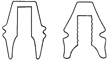
Figure 3 is an insulator which was taken from an old Fire Alarm wire in Providence, R. I., and, as near as can be ascertained, originated in Boston. As will be seen upon inspection, it is an improvement upon Mr. Swain's model in one very important respect, viz., the narrowness and depth of the inner cavity. Its only drawback is an insufficiency of material, and therefore of strength at the top, above the upper end of the support. Like the Swain model it is designed to be fixed upon an iron arm.
After the egg insulators had been in use several years the wires began to work very badly, and show a great deal of escape in wet weather. This was principally caused by the surface of the glass deteriorating from exposure, and becoming coated with dirt and smoke from locomotives and other sources.
The true cause, however, was not at that time understood or even suspected. The managers of telegraph lines "jumped" to a conclusion, which, as usual, was an erroneous one - that the trouble was owing to the egg insulator being too small at the bottom. A certain distinguished advocate of glass insulation remarked: "When I find that a parasol is a better thing than an umbrella in a big rain, then I shall begin to believe that the egg glass insulates better than the umbrella." The iron supports also came in for a large share of the general condemnation.
So all the "egg glasses" and iron arms were thrown away, and a new era of experimenting commenced. Many lines adopted the hard rubber insulator, and others the Lefferts plug. The advocates of glass returned to the old "umbrella" (Fig. 1), which they mounted on wooden pins, under the mistaken idea that these helped the insulation. This was true to a certain extent, but, on the other hand, the larger opening beneath the insulator, rendered necessary by the greater diameter of the wooden support, much more than made up the difference.
Another popular fallacy, that prevailed extensively about this time, was that the larger the insulator, and the more glass there was in it, the better it would insulate! This absurd idea, which, it is almost needless to say, was directly the reverse of the truth, was carried out on a large scale on many lines that might be mentioned. The result, of course, was far from satisfactory.
The pattern of insulator shown in Figure 4 was designed in 1865 by Mr. M. L. Wood, General Superintendent of the United States Telegraph Company. The internal screw thread shown was a subsequent invention, patented by L. A. Cauvet in 1865. This model was called the "Compromise" insulator. It was intended as a sort of cross between the "egg" and "umbrella" insulators, and appears to have been designed under the very prevalent but entirely erroneous idea that the latter was theoretically the best form of the two, but that, to obviate too great liability to fracture, it was necessary to approximate somewhat to Mr. Swain's pattern. In point of fact the "Compromise" does not insulate any better, if as well, as Figure 2, and is greatly inferior to the latter in strength. The design shown in Figure 3, on the other hand, is far superior to it in both these important particulars. Mr. Wood afterterwards [sic] afterwards improved the arrangement very much by having a collar turned on the supporting pin, nearly filling the mouth of the insulator. When the Western Union Company took possession of the United States wires in 1866 they inherited this insulator, and between that year and the present one that company has probably put up between one and two millions of them, carefully discarding, however, their only redeeming feature, the protecting collar on the supporting pin.
The Atlantic and Pacific, Pacific and Atlantic, Franklin, and other competing telegraph companies, who are always very careful to copy with ludicrous fidelity all the electrical blunders of their great rival, also adopted this model of insulator for their own wires. It is noticeable, however, that when the Western Union people get up a good thing, which they do sometimes, the imitative capacity of their competitors seems to suddenly fail!
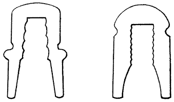
Figure 5 is an insulator composed of kryolite, or hot cast porcelain, which was designed by Messrs. Charles T. & J. N. Chester in 1869, and is used on the Fire Alarm Telegraph wires in New York City. Careful tests show that the material of which this insulator is composed is inferior to glass for this purpose, as its surface has a greater tendency to collect and retain moisture, but in its form it is far superior to any other which has yet been described. It is, in fact, nearly as perfect in this respect as it is possible to make an insulator composed entirely of glass or other equivalent material. It is of small diameter, outside as well as inside, and the length of insulating surface between the wire and the support is very great. It might be improved by making it still smaller, especially on the inside, and using an iron support instead of a wooden one.
 |
| Fig. 5 Fig. 6 |
Figure 6 is a new model, which has very recently been adopted by the Western Union Company, and which they will hereafter use in place of that shown in Fig. 4. It is made of light green glass, and is copied partly from the Chester model (Fig. 5), and partly from the Varley or English insulator. In so far as it resembles the Chester it is good, but the Varley characteristics are very objectionable as applied to this insulator, although in the original design they are much less so.
It will be noticed that the inner cavity of the new insulator is nearly like that of the Chester model, being narrow and very deep. This is the really valuable insulating feature in both models; but, in attempting to still further increase the distance between the wire and the pin, the former is carried nearly to the top of the insulator, as shown in the figure. The gain in this respect over the Chester model is only five eighths of an inch, and is all on the outside, where it is fully exposed to the wet. Practically, therefore, it does not count much. On the other hand, it gives rise to two serious mechanical difficulties. The leverage on the wooden pin is increased, rendering it more liable to break or give way, and the position of the groove so near the top renders the latter very liable to crack off. When this happens there is nothing whatever to hold the wire - it slips over the top of the pin, and away it goes. The original Varley insulator, being made of stoneware, is not liable to break in this way; and being mounted on an iron, instead of a wooden pin, the increased strain on the support causes no particular inconvenience.
Considering its insulating qualities alone the new Western Union insulator is immensely superior to their old model, shown in Fig. 4. For practical purposes, however, the Chester model (Fig. 5), if executed in glass, would be superior to it, although, as before stated, the latter might be still further improved by being made with a narrower opening and placed upon an iron support.
From what has been said it will be seen that the insulating properties of glass are purely a question of surface, and that the ingenuity of the designers of glass insulators has necessarily been exerted to make the line of superficial conduction as long and as narrow as possible, and yet preserve the necessary mechanical strength. It will readily be understood that there is a limit to all improvements in this direction, which has nearly been reached in figures 5 and 6.
 |
| Fig. 7 Fig. 8 |
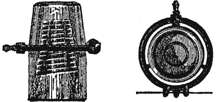
The new insulator which has just been brought out by Messrs. C. T. & J. N. Chester carries out the principle above referred to apparently to its utmost limit. It is shown in elevation in fig. 7, with a top view (fig. 8). The wire is supported by three prongs upon an iron ring surrounding the glass, but touching its surface only at three small points. The breadth of semi-conducting surface in contact with the conductor as thus reduced from three inches to three eighths of an inch, and the leakage of current over the surface of the glass diminished precisely in a corresponding ratio. In principle it is decidedly the greatest improvement which has ever been made in glass insulators. Experience will probably show the necessity of some modification in the mode of securing the iron ring shown in the figure. The screw will invariably be set up hard against the glass by the line builders and repairers, which will tend to fracture the latter by the contraction arising from changes of temperature. Some method will, doubtless, have to be devised to prevent this trouble, which, however, need be a matter of no great difficulty.
It is true that the glass insulator, even when improved eight or tenfold in respect of electrical resistance, as it undoubtedly is by this invention, falls far short of the high degree of perfection attained by the paraffin insulator, yet the large class of telegraphic constructors who prefer economy in construction to absolute perfection in results, will welcome an invention which gives them a vastly improved insulation at a very slight advance in cost.
In conclusion, a few words as to the method by which the comparative value of different insulators is experimentally arrived at, may not be out of place. A number of insulators of a given model, which are to be tested - which ought not to be less than ten to insure a fair average - are mounted upon supports in the open air, precisely as if on a line in regular service. A line wire is attached to the whole number by means of tie wires, in the usual way. With a strong battery and delicate galvanometer, arranged so that one end of the circuit connects with the "line wire" and the other with the ground, the exact resistance of the set of insulators is easily determined, and the average for each individual insulator computed. The practical tests thus obtained have been found to confirm, in all respects, the theoretical views set forth in the foregoing article.
