[Trade Journal]
Publication: Electrical World and Engineer
New York, NY, United States
vol. 42, no. 18, p. 711-713, col. 1-2
Transmission of Hudson River Power.II.
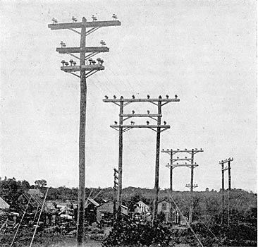
THIS extensive network of transmission lines is carried on chestnut poles that vary from 35 ft. to 60 ft. in length, the 35-ft. poles being the standard. All poles were peeled, knots were cut close, and the following were the required dimensions:
 |
Poles on tangents were regularly spaced too ft. apart, but this spacing was reduced to 50 ft. near tangent points, and heavy corners were each turned with two or more poles. All poles were set straight, but on curves the tops of poles were pulled out radially with guy wires to a distance of 6 to 12 in. Each pole was cut with three gains 1-1/2 in. deep and spaced 3 ft. between centers.
Standard cross arms for the line are to ft. 6 in. long, 4 in. thick and 6 in. deep, are chamfered 1/2 in. on their top edges and given two coats of metallic paint. Each cross arm is secured to the pole by a single through bolt 15 to 18 in. long and N in. in diameter. This bolt has a thread cut over 4 in. of its length, is used with its nut next to the cross arm, and has a washer 3 1/4 in. square and 1/4 in. thick under both head and nut. All bolts, nuts and washers are galvanized. Each cross arm is braced with one piece of galvanized angle iron made from 2-in. x 2-in. x 1/4-in. stock, 5 ft. long and bent into bow form, so that its center is 1 ft. below its ends when the brace is attached to the cross arm and pole. This brace is secured to the pole by one 5-in. x 5-in. fetter drive screw. Each end of a brace is secured to the under side of its cross arm by a single through bolt 7 in. x 5/8 in., threaded 2 in., and with a 3 1/4-in. square washer under the nut. Cross arms face in opposite directions on the two poles of each span, save that for spans of more than 100 ft. in length the cross arms are on the sides of poles opposite to the spans. On curves and corners either pole braces or guy cables were used to support each pole. The pole braces were not less than 22 in. in circumference at their tops. Guy cables are all made up of seven-strand No. 12 B.W.G. galvanized steel wire with an ultimate tensile strength of at least 80,000 pounds. Side guys were attached beneath the lower cross arm on poles in all cases, but head guys were attached above the lower arm in some instances. Clamps, thimbles, bolts and nuts for guy cables are all galvanized and of malleable or wrought iron or steel. Wooden guy anchors are 6 ft. long and not less than 30 in. in circumference. Guy rods are 8 ft. x 5/8 in., provided with an eye at one end, threaded 2 in. at the other, each fitted with two nuts and one washer, and all are of wrought iron or mild steel.
 |
| Fig. 7. Special Pole Construction |
 |
| Fig. 8. Tower for Transmission Lines. |
Each of the 10-ft., 6-in. arms that are standard on this work carry four insulator pins spaced 3 ft. apart on centers. All pins are iron and each pin is secured to its cross arm by a 3/4-in. bolt or stud of wrought iron or steel that passes down through it and is secured underneath by a nut and washer. Two styles of pins are in use, one intended for straight lines and the other for curves and corners. The pin for straight work is made up of a malleable iron casting with a 3/4-in. wrought iron or steel stud threaded into its base. This stud passes down through the cross arm and the casting stands above the arm and carries the insulator. In pins intended for curves and corners a bolt passes entirely through the cast-iron part and then down through the arm with a nut and washer underneath. For this strain pin the length of the through bolt is 16 1/2 in. over all, the length of the cast-iron part that stands above the cross arm is 8-3/4 in., and the flange of the casting that bears on the arm is 3-3/4 x 5 in. The top of this casting is 1-3/8 in. in diameter and has ¼-in. threads for the insulator.
| |||
| Fig. 9. Crossing D. & H. Tracks at Saratoga |
All insulators used on these pins are of porcelain with brown glaze, and are in two styles. The type of insulator of which the greatest number have been used is cast in a single piece with double petticoats. The Locke insulator that has more recently been adopted is cast in three parts and then cemented together. On these insulators the required puncturing test is 80,000 volts during five minutes after the insulator has been soaked 24 hours in water. Each petticoat is tested separately with 40,000 volts. Each insulator was secured to its pin by liquid Portland cement poured into the pin hole of the insulator while the loose pin top was held in a central position. On the built-up insulators three petticoats are provided. When this insulator is in position on its pin and cross arm, its lowest petticoat is 4 1/4, in. above the top of the arm. The next higher petticoat is 6 3/4 in. above the arm, and the outside petticoat has its lower edge 7 1/2 in. from the arm. In diameter the highest or outside petticoat measures 8 1/2 in., the middle petticoat 5 1/2 in., and the lowest petticoat 4 in. When standing alone on its longest petticoat the height of this insulator is 6 3/4 in.
Both styles of porcelain insulators used permit the line wires to be tied to either their tops or sides, but in the construction the lines were tied to their sides. Insulators for the transmission lines were required to withstand a transverse strain of 3,000 pounds, and thick petticoats were specified in order to avoid breaking under shotgun practice. For the telephone wires which follow all the transmission circuits a Locke No. 7 porcelain insulator was employed.
All of the transmission circuits are made up of solid, hard-drawn bare copper wire, required to be of not less than 98.5 per cent. conductivity. Tie wires for all sizes of the transmission conductors were of No. 4 B. & S. G. soft-drawn bare copper wire, and each was approximately 30 in. in length.
Splices in the main conductors were made with trolley sleeves at least 12 in. long, and heat was applied only at the center of each sleeve, so as to avoid annealing the hard-drawn copper wire. The soldered joints thus made with sleeves were allowed to cool slowly to avoid the annealing just named. Wires were strung on the standard ioo-ft. spans, with deflections depending on the temperature, according to the following table:
Degrees Fahrenheit ... 0 10 20 30 40 50 60 70
Deflection in inches ..... 6 9 12 14 16 17 19 20
In each three-phase circuit the wires were transposed 1/3 of a turn for each section of 130 poles, so that each conductor passes through a complete circle every 7.5 miles, there being 52 poles per mile of straight line.
The three four-pin arms per pole permit the erection of four three-phase circuits with each wire 36 in. from any other. Two wires of a circuit were mounted on the two insulators that occupy that half of a top cross arm on one side of its pole. The third wire of this circuit was mounted on the insulator at the end of the next lower arm and directly beneath the outer of the two wires of that circuit on the top arm. This arrangement left the inner insulator on the same end of the middle arm and the two insulators on the corresponding end of the third or lowest cross arm for another three-wire circuit. On the other side of each pole the six wires of two circuits are arranged in an exactly similar way. Telephone lines over the transmission system are of No. 12 hard-drawn copper wire, 5 ft. below the power wires and transposed every three poles.
 |
| Fig. 10. Strain Insulator Pin. |
Special constructions were necessary at several points on the transmission lines. In Saratoga, where the circuits cross the tracks of the Delaware & Hudson Railway, a complete network of guard wires was built beneath the high-tension circuits. For this purpose special cross arms were mounted on two poles set about 9 ft. apart in a plane at right angles with the line. The top cross arm is 16 ft., the middle arm 10.5 ft., and the lowest arm 14 ft. long, there being three to each pair of poles. The top arm carries six insulators, the middle arm two insulators, and the lowest arm four insulators. On the four inside insulators of the top arm and the two insulators of the middle arm the two three-phase circuits are strung. On the end insulators of the top cross arm and on the four insulators of the bottom arm heavy galvanized iron wires are strung, and at short intervals along these iron wires between the several pairs of poles other iron wires are secured to the former transversely, so that a mesh of these interwoven guard wires extends entirely over the railway crossing and beneath the power circuits.
Before entering the Schenectady switch house at the works of the General Electric Company, the transmission lines cross the tracks of the New York Central Railway and the Erie Canal overhead. This crossing is made with wooden towers each 66.5 ft. high from base to the upper side of the top cross arm, and set 10.5 ft. in the ground. One of these towers measures 22 ft. square at its base and its two pairs of 65-ft. posts are 9 ft. apart on centers at the top. Two arms, each of 6 x 10-in. stock, carry the transmission lines, the top arm being 17 ft. and the lower arm 4 ft. beneath, 23 ft. long. Each wire of the transmission circuits on these arms is supported between two insulators set close together. Most of the timber in each of these towers, including the four 65-ft. posts, is Georgia pine, and the remainder is chestnut.
The timbers of the towers are treated with carbolinium avenarius, and all the iron plates and bolts on the underground parts are covered with coal tar. No guard wires for protection from lightning are used on any of the above transmission lines, and lightning arresters are connected to the wires only at the generating plants, sub-stations and switch houses. Before entering a generating or sub-station, or switch house, each bare copper conductor of the transmission circuits ends, and is connected to an insulated wire. Connection between each bare conductor and its insulated terminal is made with one of the trolley sleeves already mentioned. Each of these insulated terminal wires, regardless of its size, is covered first with a layer of rubber 9/32 in. thick, then with 9/32 in. of varnished cambric wound on, and finally with two layers of weather-proof braid outside of the cambric.
| |||
| Fig. 11. Mountain Line. |
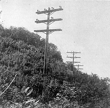
The standard voltage of transmission on lines running from the power plant at Spier Falls is 30,000, but lower voltages may be had by varying the connections of taps on the transformers. At the General Electric works and at the Watervliet sub-station energy is delivered from Spier Falls at a pressure of about 26,500 volts. Transmission lines from the power plant at Mechanicsville are supplied with current at about 12,000 volts, and deliver it to the General Electric works and the Watervliet sub-station at 10,800 volts approximately, also to the sub-stations of the lighting companies in Troy and Albany, and of the United Traction Company there at the same pressure.
At each generating plant, sub-station and switch house where the transmission lines enter or leave a weather shield is provided. Each of these weather shields is built up of boards on the side of the building where the high-tension circuits enter, and has a slanting roof with gutter so arranged that water falling on the roof is carried off at the sides and does not drip down onto the wires. The outside, vertical wall of each weather shield is about 4 ft. from the brick wall of the building through which the wires pass. In this outside, vertical wall of the weather shield there is a circular hole to in. in diameter for each wire that is to pass through it. These holes are spaced from 20 to 21 in. apart on centers, and the entering lines pass as nearly as possible through their centers. Between the outside, vertical wall of each weather shield and the brick wall parallel with it there are porcelain insulators to which the bare transmission lines are attached. Close to the point of this attachment on each line the joint between the bare conductor and the rubber and paper-insulated terminal cable already mentioned is made. Opposite each hole in the weather shield is a circular hole of 15 in. diameter in the brick wall of the building. Into this circular opening in the brickwork fits a wooden ring of 11 inside and 15 in. outside diameter and 2 in. thick. To this wooden ring is secured a disc of hard fibre 15 in. in diameter, in. thick, and with a center hole just large enough to admit a porcelain tube of two in. internal diameter. Each of these porcelain tubes is 24 in. long, and one of the insulated terminal cables already mentioned passes through it. In this way each wire of the transmission lines enters the generating and sub-stations and switch houses so that rain or snow cannot follow, as each opening through a brick wall is entirely closed. Just inside of the brick wall through which it passes, each insulated terminal cable is secured to a porcelain insulator. Each outgoing line at a generating station and each incoming line at a switch house or sub-station is connected to the middle terminal of a single-pole, double-blade lever switch near the circular opening through which it passes in the brick wall. Switches used for this purpose are of a uniform type throughout the system, and each includes three large Locke porcelain insulators on which are mounted cast-iron caps that carry the contact parts. The middle insulator of the three carries two copper switch blades, each 1/4 in. x 2 in. x 16 1/2 in., that are in electrical connection. One of these switch blades is intended to make contact with the terminals on one of the other two insulators, and the other blade makes contact with the terminals of the remaining insulator. The terminals at one end of this switch are permanently joined to a group of lightning arresters, and the terminals at the other end connect with one pole of an oil switch. From the foregoing it may be seen that the wires of an outgoing line at a power station, or of an incoming line at a switch house or substation may be either disconnected from the lightning arresters and left connected to the oil switches, or vice versa. On the 30,000-volt lines twelve lightning arresters in series are connected to one terminal of the switch just mentioned, and each lightning arrester has four air-gaps and two carbon rods in series. For the group of twelve arresters this gives a series of 48 air-gaps and 24 carbon rods. The air-gaps are between short brass cylinders, and each is approximately 1/16 in. long. Each carbon rod is said to have a resistance of 200 ohms. Each group of lightning arresters is located in a brick and stone compartment approximately 9.5 ft. high, 2 ft. wide, 28 in. deep and open at the front, but these dimensions vary at different stations. In each compartment or cell the arresters are mounted on two wooden uprights each 3 in. x 3 in. x 7 ft. 9 in., and these uprights are in turn supported on four of the iron-capped insulators already named. The lever switches are secured to wooden uprights in cells similar to those provided for the lightning arresters.
Another important purpose to which the single-pole, double-blade lever switches are put is that of transferring any incoming to any outgoing line at a switch house or sub-station, when this is desirable, because of trouble or repairs. To provide for this result each wire of all the incoming lines is brought to a terminal at one end of a switch, and each wire of all the outgoing lines is brought to a terminal at the other end of a switch. To the third or center terminal of each switch, where the two independent blades are mounted, connection is made from one side of a single-pole, single-throw lever switch. The other terminals of these single-pole, single-throw switches may be connected in pairs, as desired, by cables. When both blades of the single-pole, double-throw switches are closed and the single-pole, single-throw switch connected therewith is open, the incoming and outgoing lines are connected in their regular order. By opening one blade on each of any two of the double-blade switches, and connecting the center points of these switches through their two single-blade switches, the incoming and outgoing lines of the former switches may be joined.
At each generating station or sub-station or switch house the several groups of lightning arresters are connected to a common ground wire and plate. The standard construction for this ground connection includes a bare 4/0 copper wire leading from the lightning arresters to a cast-iron ground plate buried outside of the building. This cast-iron ground plate is 4 ft. square, 3/4 in, thick and has a boss at one side that increases the thickness to 2.5 in. This boss is tapped for a 1.5-in. brass plug, and into this plug the 4/0 wire from the lightning arresters is soldered. Beneath the cast-iron plate a layer of broken coke is placed, and another layer of coke goes on top of the plate before the hole in which it is buried is filled with earth.
At generating stations, switch houses and sub-stations throughout this system the general plan is to give the greatest facility for the connection of any particular generator or step-up transformer to any transmission line, any transmission line to any step-down transformer, and any distribution line to the bus-bars supplied with energy from any generator. The result of this general plan may be traced, for instance, from the station at Spier Falls to the distribution circuits at any sub-station. At Spier Falls either 2,000-volt, three-phase generator may be connected by knife switches either to the primary coils of a particular group of transformers that raise the voltage to 30,00o, or to a set of 2,000-volt bus-bars. By means of these bus-bars the particular generator in question may be operated in multiple with all of the other generators in the station, or may be connected to any desired group of transformers. Each group of three step-up transformers may in turn be connected on its primary side with any one generator, or may be fed from the 2,000-volt bus-bars.
 |
| Fig. 12. Elevation Showing Arrangement of Apparatus in Schenectady Switch House. |
After passing through a triple-pole, 30,000-volt oil switch the circuit from the secondary coils of each group of transformers goes to double-blade knife switches of the sort before mentioned, and these switches suffice to connect the circuit in question with either of two sets of 30.000-volt bus-bars. These bus-bars are divided into sections by other knife switches, so that the section of each set that is capable of being directly joined with a particular group of transformers may be isolated from the other sections of its set, or not, as desired. Either of the two bus-bar sections just mentioned may be connected with either of two 30,000-volt oil switches. Each of these oil switches is connected through knife switches with a three-phase transmission circuit. The net result of all these arrangements is that any transmission circuit may be supplied with energy either from all the generators and transformers operating in multiple, or from any particular sets of generators and transformers. or from any one generator and any one group of three transformers.
